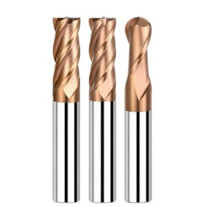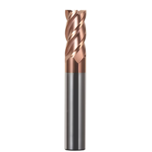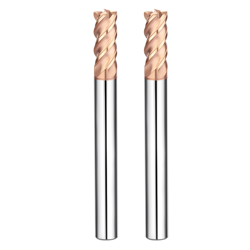
For the past two weeks, our technical team has practically lived in a client’s mold shop. This client is a Tier 2 supplier for major European automotive brands, specializing in large-scale die-casting molds. They hit a wall: while finishing Cr12MoV cold-work mold steel—clocking in at a brutal HRC64–66—their “premium” carbide end mills were repeatedly “going on strike.”
These weren’t typical wear-and-tear cases. The tools were micro-chipping without warning or snapping clean off at the neck. Beyond the cost of ruined HRC65 end mills, the real disaster was the broken fragments lodged in deep cavities. It nearly scrapped a mold that already had 40+ hours of machining time invested.
As veterans with 16 years on the shop floor, we knew this wasn’t just about “insufficient hardness.” It was a classic failure of substrate toughness versus coating stress relief—a common trap when using high-performance carbide end mills in ultra-hard materials with long overhangs. A common misconception among peers is that an HRC65 rating is a “set it and forget it” fix. In reality, with “bone-hard” materials, a 2% deviation in coolant concentration or a tiny 0.005mm run-out in a shrink-fit holder can turn a premium tool into expensive scrap metal.
To solve the chip evacuation and thermal stability issues, we overhauled our custom carbide end mill strategy. We stopped chasing sheer “sharpness” and prioritized “edge stability.” We ignored idealized lab data and focused on the shop floor reality: how to make a tool “bite” into hardened steel reliably under high-load vibration.
Have you ever felt that despair? You follow the technical manual to the letter, yet the tool inexplicably fails before the finish line?
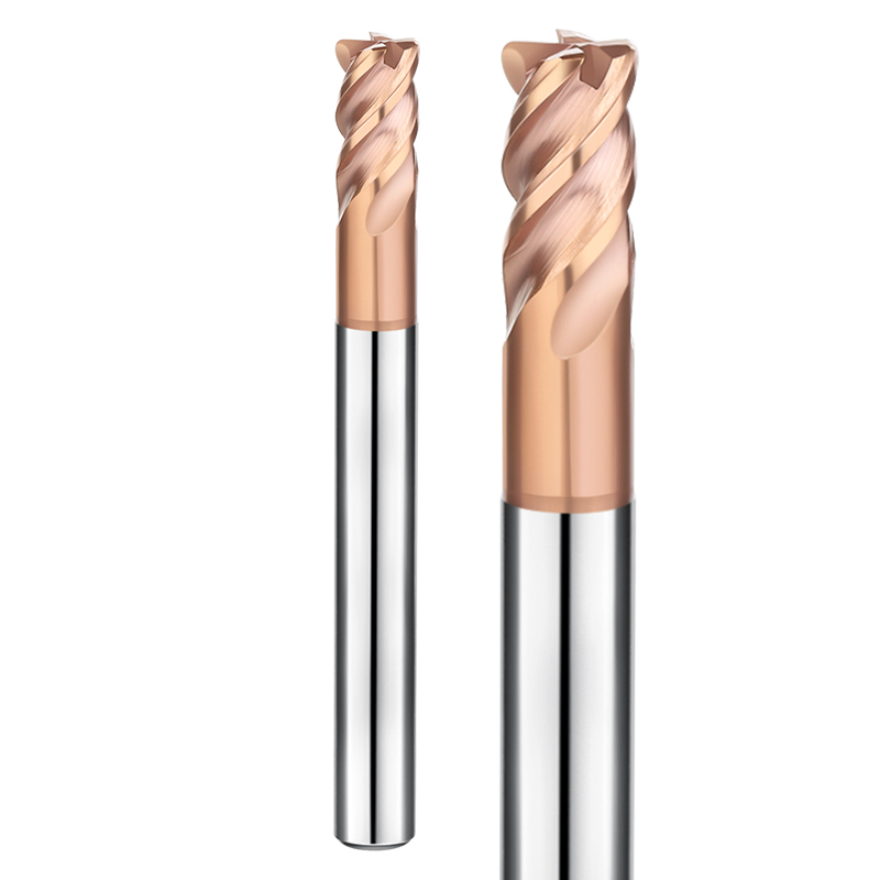
When Machining High-Hardness Materials, Substrate Toughness is More Critical Than Hardness
The intuition is simple: use the hardest tool for the hardest steel. But 16 years in the trenches have taught us otherwise. Once you cross HRC60, the “backbone” of your carbide end mill for hardened steel—the physical toughness—matters more than the coating’s Vickers hardness. If the substrate is too brittle, it’s like hitting a stone with glass. It’s hard, but the slightest force fluctuation causes crystalline chipping.
When we consult for precision mold shops in the US and Europe, we often persuade them to abandon cheap tools that boast high hardness but lack “guts.” In high-frequency intermittent cutting, thermal stress accumulates instantly. If the substrate lacks flexural strength and damping, that stress leads to immediate chipping. We prefer ultra-fine grain structures. These allow the tool to stay sharp while providing a minute “cushion”—much like spring steel. This balance is our primary criterion for extreme conditions.
From HRC55 to HRC65: Why Conventional Carbide End Mills Shatter on Engagement
Below HRC55, an aggressive feed might just accelerate wear. But cross the HRC65 threshold, and engagement resistance increases exponentially. Many conventional carbide end mills shatter within tenths of a second. The reason? Their edge honing can’t handle the instantaneous compressive shock. Since the workpiece has lost its plasticity, the entire cutting force hammers back into the edge. Without precise micro-level protection, shattering is inevitable.
We recently analyzed a failure for a mold exporter. Their standard tools snapped the moment the spindle engaged. Under the microscope, we saw classic brittle fracture patterns. These tools prioritized chip space by compromising the core diameter. When they hit the reactive force of HRC65 steel, the structural rigidity collapsed. These failures don’t just kill the tool; they leave irreparable impact marks on a nearly finished part.
Substrate Ratios from the Field: How Impact Resistance Determines the Lifespan of HRC65 End Mills
During a technical exchange with a German engineering firm, we co-developed a substrate logic for extreme hardness. They were obsessive about stability, demanding that HRC65 end mills maintain dimensional consistency over a continuous 8-hour cycle. Our solution? We increased the cobalt (Co) content and used a vacuum sintering process to eliminate microscopic porosity.
Yes, more cobalt slightly lowers the theoretical hardness value. However, the resulting impact resistance stops micro-cracks from propagating through the cutting edge. This “addition and subtraction” strategy is how we solve B2B pain points. We would much rather see a tool undergo predictable, gradual wear than suffer a catastrophic “heart attack” mid-cut. When you source tools for this range, ask about the transverse rupture strength. It’s a much better indicator of success than a standard hardness data sheet.
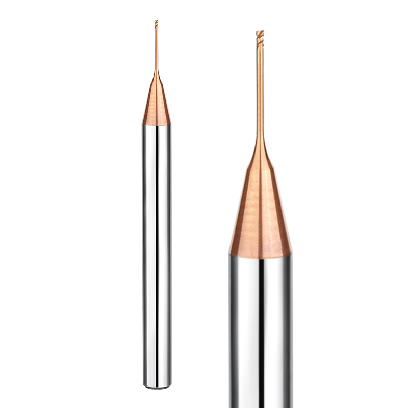
True High Performance Lies Not in Spindle Speed, but in Thermal Stress Management
In many high-precision shops, I see operators blindly cranking up spindle speeds to hit tight deadlines. Usually, it’s counterproductive. When you’re machining hardened mold steels, the real value of high-performance carbide end mills isn’t how high they can push the tachometer; it’s how effectively they dissipate heat. When cutting temperatures spike past 800°C, a tool that can’t manage thermal stress through geometric design will develop micro-cracks from thermal fatigue. This is the #1 killer of tools, long before standard wear sets in.
We once consulted for a client struggling with large automotive body panel molds. They couldn’t hit their target speeds because their tools were “burning up” during dry machining. We actually recommended reducing the spindle speed by 15% while increasing the feed per tooth. By using the chips to carry the heat away from the workpiece, we achieved a higher metal removal rate (MRR) and better tool life. That mastery over heat is what separates a standard cutter from a true high-performance tool.
Coating Delamination—The Killer in Hard Milling: How We Optimize Adhesion
In hard milling, once the coating peels, the carbide substrate collapses almost instantly. It’s like a soldier losing his armor. This failure usually starts at the very tip where shear stress is highest. To stop this, we’ve moved away from basic grit-blasting. Instead, we use advanced PVD or CVD processes that “embed” the nanoscale coating into the substrate’s crystal lattice.
Last year, a medical device manufacturer came to us with “coating spallation” issues. Their tools were flaking like old paint. We overhauled their interface treatment and designed a specific stress gradient between the coating layers. This gave the coating the elastic flexibility to survive the constant expansion and contraction of high-heat cycles. If your tools are flaking in large patches, your coating adhesion wasn’t designed for the thermal shock of HRC65+ machining.
The Power of Negative Rake: Why HRC65 Requires “Dull” Edges
Machinists used to aluminum are often shocked the first time they hold an HRC65 end mill. They ask, “Why does this feel dull?” That is the intentional negative rake angle. A razor-sharp edge hitting HRC65 steel is like a glass knife hitting a rock—it will shatter instantly. Through a precision honing process, we ground a microscopic radius or chamfer onto the edge. This shifts the cutting force away from the fragile tip and distributes it back into the tool body.
Finding the “sweet spot” for this edge preparation is tough. If it’s too dull, you get chatter; too sharp, and it chips. We fine-tune these radii within microns based on the client’s machine rigidity. In the world of extreme hardness, a calculated “dullness” is actually a superior form of sharpness. It allows the tool to penetrate the surface without microscopic chipping, making continuous, stable machining possible.
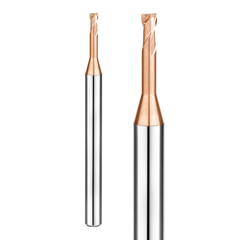
Solving Deep Cavity Vibration with Custom Carbide End Mills
Standard catalog tools often fail when you hit an aspect ratio (length-to-diameter) of 5:1 or 8:1. The moment the tool enters the cut, that high-frequency shriek tells you the vibration is out of control. This ruins the surface finish and induces fatigue cracks in the carbide. In these cases, don’t just tweak your RPM—look at the structural design of a custom carbide end mill.
The secret to killing vibration is disrupting resonance. We custom-engineer the neck diameter, taper, and flute length so the tool’s natural frequency doesn’t match the spindle’s frequency. We often sacrifice a bit of chip space for a thicker core diameter. In high-hardness machining, rigidity beats chip evacuation every time.
Overhang vs Rigidity: Our Clearance Design Logic
When a client needs to reach 50mm deep in a tight space, it’s a game of millimeters. If the shank is too thin, the tool deflects away from the cut, ruining your tolerances. If it’s too thick, it rubs the cavity wall. We use a progressive tapered-neck design. This combines a short flute with a reinforced neck, ensuring cutting forces are transferred immediately to the rigid shank.
My advice: never use a long cutting edge for a deep cavity. A long edge just creates more surface area for the material to push back against, causing the tool to bend. We usually keep the cutting edge at 1.5x the diameter and precision-grind the rest as a relief neck. It costs more to make, but it lets you double your feed rate and sleep better knowing the tool won’t snap.
Case Study: Disruption through Unequal Helix Angles
We recently solved a perpendicularity issue for a client milling an HRC65 die-casting mold. Standard tools were deflecting just enough to ruin the part. We developed a custom carbide end mill using Unequal Indexing and Variable Helix Angles (e.g., a 35°/38° split). This ensures the four cutting edges hit the material at different times and angles.
By staggering the entry points, we physically disrupted the vibration waves before they could synchronize. Even under high-load, dry-cutting conditions, the machine stayed quiet and the finish was like a mirror. If you’re seeing ripples or chatter marks in your deep cavities, it’s time to move past symmetrical tools and look at asymmetrical geometry.
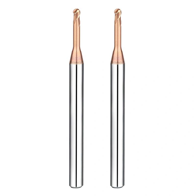
Three “Non-Tool” Variables That Dictate Success in HRC65 Milling
Many believe that simply buying top-tier cutters makes machining HRC65 hardened steel halfway successful. In our experience, that’s a dangerous oversimplification. We have seen far too many clients use $300 HRC65 end mills in antiquated fixtures with excessive runout, or on spindles plagued by thermal displacement. It is like fitting Formula 1 tires onto a vintage truck; not only will you fail to hit top speeds, but the systemic mismatch will ruin those expensive tools in minutes.
Once workpiece hardness exceeds HRC60, machining becomes a “rigidity equilibrium.” Beyond the tool itself, three variables determine if you are performing a controlled cut or merely “gnawing” at the material: the machine’s dynamic response, the penetration of your cooling system (air or mist), and the runout at the clamping interface. If you don’t optimize these factors, even the finest carbide end mill will struggle to deliver consistent results.
Why Your Surface Finish Fails—Even with Premium Carbide End Mills
Peers often ask me why, despite using the best carbide end mills for hardened steel, their mold surfaces still show stubborn “fish-scale” patterns or chatter. At HRC65, steel loses the plastic flow characteristics of softer materials. The chips are extremely fine and powdery. If your system—machine, fixture, and tool—has even a micron of deflection, the edge will “bounce” on contact. These high-frequency micro-vibrations are the true culprits behind a poor finish.
I always advise shop floor teams to review their toolpath design first. If your finishing allowance is uneven after roughing, the sudden force fluctuations will cause the tool to deflect. Even with premium tools, sharp right-angle turns instead of smooth arc transitions make a mirror finish impossible. This isn’t a tool fault; it’s a “soft steel” mindset being applied to high-hardness reality.
Clamping Systems: The Key to Unleashing High-Performance Carbide End Mills
When troubleshooting for high-end clients in North America, we check the tool holders first. For high-performance carbide end mills, traditional ER collets are often unreliable for HRC65 work. Their radial runout and clamping force rarely withstand the massive reaction forces. If runout exceeds just 0.005 mm, a single cutting edge takes double or triple the load, leading to premature failure.
We recommend shrink-fit or high-precision hydraulic holders. Shrink-fit holders provide 360-degree uniform clamping and exceptionally low runout, ensuring every flute participates equally. This is vital for preserving delicate nano-coatings. To get the maximum life from high-performance tools, your clamping interface must be as rigid as an integral extension of the machine spindle. If you’re still using a five-year-old collet for HRC65 work, don’t waste your money on expensive tools.
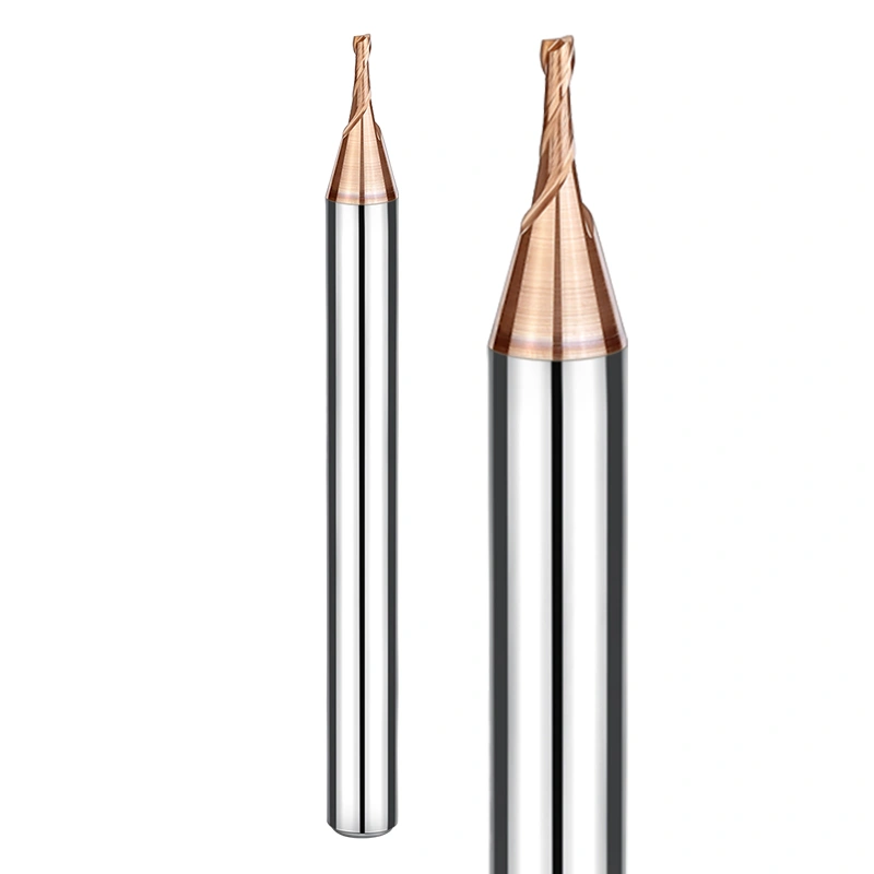
Practical Parameter Recommendations for HRC65+ Machining
In the shop, we say: “The catalog is static; the machinist is dynamic.” Reciting manufacturer data for HRC65+ work often puts you at a disadvantage. The goal is to find the “sweet spot” where machine load, heat, and tool life balance out. If your machine is high-end but you see excessive sparking, check your radial depth of cut (Ae). Keep it within 5% to 10% of the cutter diameter. High-frequency, shallow cuts effectively mitigate the instantaneous stress on the carbide end mill.
Hard-metal machining is about mastering the rhythm. For large face milling, increase your surface speed to allow air cooling to evacuate chips faster, preventing recutting. These adjustments aren’t for “speed”—they are for predictability. If your actual performance doesn’t match your parameters, feel free to share your part drawings or conditions with us. We are happy to conduct a detailed comparative analysis for you.
Beyond the Textbook: Real-World Feed and Depth Guidelines
Textbook ranges are often too broad to be useful. In our experience, the cutting logic must shift radically when moving from HRC55 to HRC65. At HRC60, you can maintain a stable feed; at HRC65, your feed per tooth (Fz) must be much more conservative—usually between 0.01 mm and 0.03 mm.
The axial depth of cut (Ap) directly influences vibration frequency. If you see “deflection marks” during side milling, reduce the Ap and increase the feed rate—a technique known as High Feed Milling. This “fast and shallow” approach was learned through years of broken tools and scrapped workpieces. If you’re unsure about a specific grade of tool steel, send us the material grade; we can provide reference values that actually work on the floor.
Monitoring Wear: How to Know When Your HRC65 End Mill is Finished
In high-hardness machining, waiting for a screech or sparks is usually too late. Watch your chips. If they turn from light gray to deep purple or dark red, the flank wear on your HRC65 end mill has exceeded critical limits, and the coating has failed.
Also, look for the “white line” at the tip. Under magnification, a band of white reflection means the substrate is exposed. Forcing the tool further will likely snap it off inside your workpiece. We recommend keeping a machining log. Use the wear trends of the first part to set a replacement cycle for the batch. If you are puzzled by your tool life, send us photos of your wear patterns. We can usually tell if the issue is your parameters or the tool configuration itself.