Last month, an automotive mold supervisor in Michigan sent us a micro-video. A set of D2 cavities, heat-treated to 62 HRC, showed severe edge chipping after twenty minutes on a 5-axis mill. Instead of a mirror finish, the steel surface showed whitish scratches from material tearing. The customer was frustrated: “We followed the book on speeds and feeds. Spindle runout was under 3 microns. Why is the tool tip still tearing up the surface?”
In our fifteen years of manufacturing cutting tools and troubleshooting shop floors, we have seen this failure mode hundreds of times.
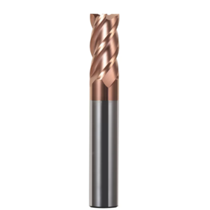
When cutting hard steels between 50 HRC and 65 HRC, shops often blame spindle RPM or machine rigidity. After inspecting countless failures, we know the real cause is microscopic. A general-purpose carbide end mill cutter cannot handle extreme shear stresses. It also cannot survive dry cutting temperatures that spike past 900°C.
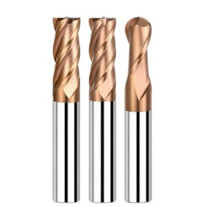
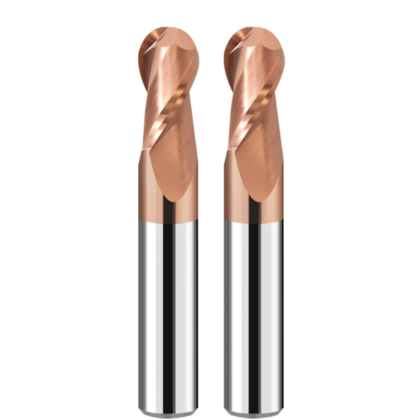
Pre-hardened tool steels have high yield strength and offer zero cushion for plastic deformation. Picking the wrong cutter geometry causes immediate edge breakdown. Forcing a 4 flutes ball nose end mill into deep slots leads to chip re-cutting. Pair that with zero surface speed at the tool tip, and edges chip in seconds. Conversely, a thin-cored 2 flutes ball nose end mill flexes during semi-finishing, creating chatter that destroys the coating.
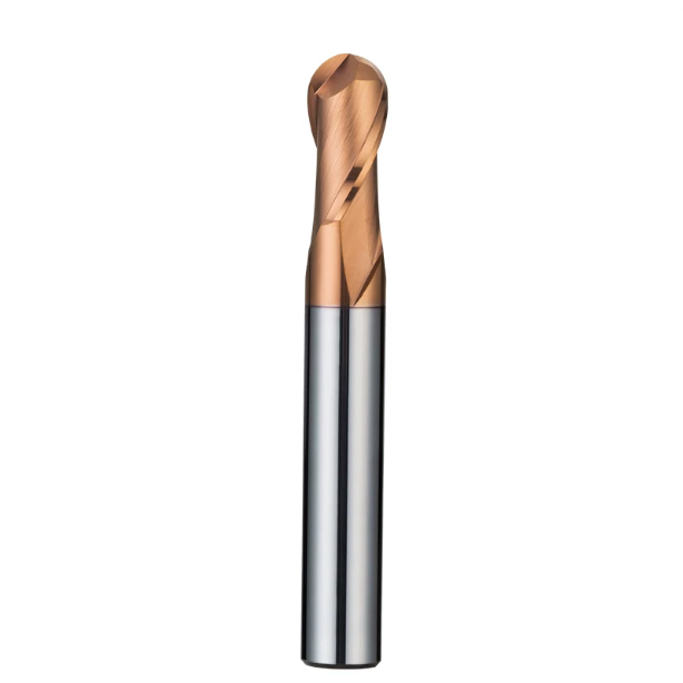
As a dedicated carbide ball nose end mill manufacturer, we spend our time between CNC tool grinders and customer machining centers. We balance micro-grain tungsten carbide substrates, edge preparation, and nano-coatings. Our goal is straightforward: ensuring a specialized carbide ball nose end mill for hardened steel shears cleanly across 60+ HRC steels rather than plowing through raw friction.
When running an expensive, fully hardened die cavity, can you walk away from your machine tonight confident you won’t hear that dull snap of a broken tool?
Pain Points in Machining 50–65 HRC Mold Steel: The Reality of Tool Failure Observed in North America
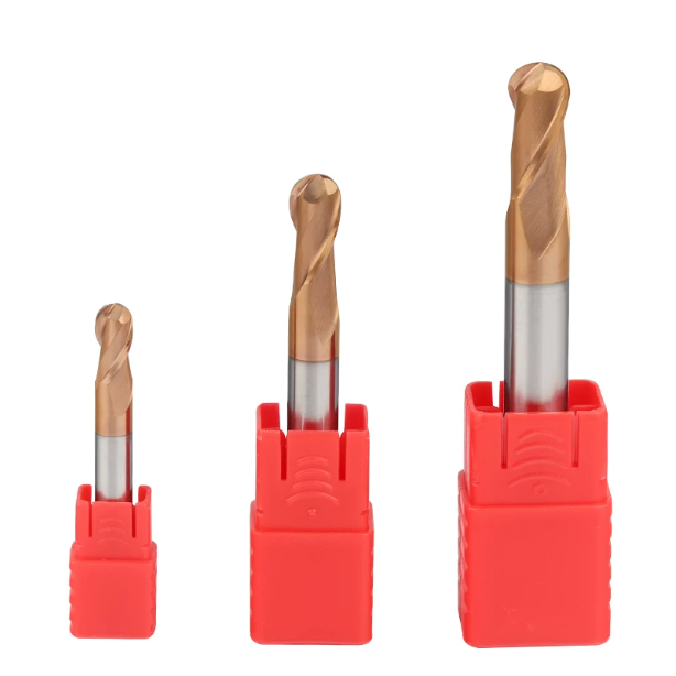
Whenever we walk through mold facilities across the Midwest, we see the same telltale sign. Discarded tools line the workstations, each showing greyish-white chipping along the ball profile. Many machinists treat 50 to 65 HRC steel as merely “a bit harder than 4140.” However, the cutting mechanics are fundamentally different. Hardened steel offers almost zero plastic slip during shearing, causing cutting forces to spike into sharp, localized shock loads.
Heat concentration is the secondary killer. Hardened tool steels have exceptionally low thermal conductivity. Unlike aluminum machining, where escaping chips carry away thermal energy, hard milling leaves up to 80% of the heat at the cutting edge. Under these harsh conditions, a conventional carbide ball nose end mill rarely dies of normal flank wear. Instead, it fails abruptly from brittle thermal-mechanical fracture.
Why the Lifespan of Standard Carbide End Mills Plummets When Machining Heat-Treated Materials (D2 / H13 / CPM-1V)
Two years ago in Detroit, a stamping die customer used a general-purpose carbide end mill cutter on 60 HRC D2 steel. The tool barely survived fifteen minutes before emitting a high-pitched screech. Under our shop microscope, the primary cutting edge revealed continuous shell-like flaking. Dense, hard eutectic carbides inside the alloy had hammered against the insufficiently rigid cutting edge at high speeds.
Microscopic analysis confirmed that the cobalt binder in general-purpose carbide substrates cannot endure extreme cutting zones. When interface temperatures exceed 800°C, the cobalt binder softens rapidly. This leaves the tungsten carbide grains unsupported. For materials like D2, H13, or CPM-1V that combine extreme hardness with poor heat dissipation, an unoptimized cutter lacks the hot hardness required to resist micro-fractures.
The “Zero Surface Speed” Issue at the Ball-Nose Center and Premature Failure Caused by “Trailing-Edge Extrusion”
Running a ball nose tool perpendicular to a workpiece forces you into an unforgiving physical reality. Cutting speed depends entirely on the effective cutting radius. As your cut approaches the center tip, that diameter shrinks toward zero. This reduces actual surface footage to zero. The dead center of the tool cannot slice material; it simply plows and extrudes the hardened steel. Our infrared thermal tests prove local contact temperatures in this dead zone easily surpass 900°C.
Machinists often react to center-drag marks or torn workpiece surfaces by ramping up spindle RPM. This is a trap. Increasing spindle speed never fixes zero surface speed at the dead center. It only overheats the adjacent cutting lips and breaks down coating adhesion. That is why we frequently see a high-performance carbide ball nose end mill for hardened steel with clean outer flutes, while the center tip is burned flat and chipped away.
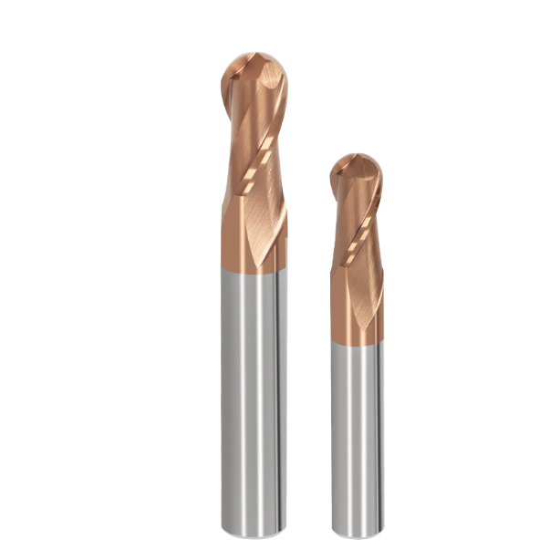
Balancing Cutting Edge Geometry and Chip Evacuation: Real-World Operational Limits of 2-Flute vs 4-Flute Ball-Nose End Mills
Tooling catalogs print ideal feeds and speeds, but real-world setups are never ideal. Once steel hardness tops 50 HRC, you face a direct physical tradeoff between flute chip capacity and core diameter rigidity. Programmers constantly face this dilemma. Do you thicken the web for structural strength, or deepen the flutes for smooth chip clearance? Guessing on flute count often leads to broken cutters or stubborn chatter patterns across finished surfaces.
Over years of logging cutting forces and tool deflection, we know flute count comes down to chip space versus tool body stiffness. Neither design is universally superior. It is a question of whether your tool path cuts inside a restricted cavity or sweeps across an open surface at high feed rates. Overlooking these practical boundaries while selecting a high-grade carbide end mill cutter inevitably leads to deflection, chip packing, or snapped shanks.
Chip Evacuation and Anti-Entanglement Performance of 2-Flute Ball Nose End Mills in Deep-Cavity Corner Cleaning (55 HRC)
In tight features like deep ribs or narrow mold pockets with depth-to-diameter ratios past 4:1, chip packing is the primary cause of cutter failure. At a die-cast shop in Ohio, machinists swapped to four-flute tools for better stiffness. However, the tight flutes could not clear fine, hardened chips under shop air. The trapped chips were dragged under the flutes and re-cut, creating localized impact spikes that punched micro-notches straight into the cutting edge.
In these enclosed corners, a 2 flutes ball nose end mill remains the most reliable option. Two balanced flutes offer up to 35% more chip gullet volume than multi-flute designs. This provides a clear exit path for hot chips pushed by compressed air. Even with reduced core thickness, preventing chip packing and friction is far more critical for edge survival when reaching deep into tight pockets.
Rigidity and Feed Rate Multiplication with 4-Flute Ball Nose End Mills in Semi-Finishing Hardened Steel (60–65 HRC)
The moment your operations move to semi-finishing open 3D surfaces, chip buildup stops being the main hazard, and tool deflection takes over. When machining tool steels hardened past 60 HRC, microscopic radial vibration causes immediate coating delamination. Running a two-flute tool here introduces deflection problems. The thin core flexes under high-speed reversing loads, setting off high-frequency chatter.
Switching to a 4 flutes ball nose end mill engineered with a heavy core stabilizes the cut immediately. By designing the core web to exceed 65% of the outer diameter, bending stiffness increases substantially. For final finishing, we suggest taking light axial cuts (Ap ≤ 0.05D). Spreading the chip load over four edges while increasing table feed suppresses vibration, leaving a near-mirror surface finish with no tool mark chatter.
The Decisive Impact of Ball Nose Radius Tolerance and Runout on Actual Tool Life
Beyond flute count, many machine operators overlook how profile tolerance interacts with spindle runout. A tool runout of 0.0003″ (0.008 mm) might go unnoticed in pre-hardened steels, but 62 HRC steel offers zero compliance. At that hardness, runout over 0.0002″ forces the entire chip load onto a single flute. This ruins surface accuracy and overloads that individual cutting lip until it micro-chips.
On our CNC tool grinding and inspection lines, we proved that holding the profile accuracy of a carbide ball nose end mill within ±0.005 mm—while keeping installed spindle runout under 0.003 mm—more than doubles tool life on hardened steels. Reliable hard milling requires addressing the entire machining assembly. High-precision shrink-fit or hydraulic holders, balanced tool assemblies, and tight runout tolerances must work together as a single rigid unit.
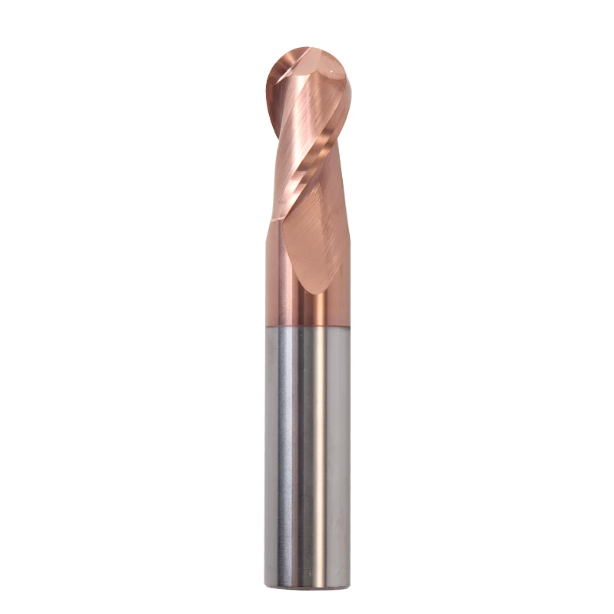
Specification Selection and Rigidity Matching: Limiting Overhang and Ratios for Standard Ball End Mills in Hard Milling
When reviewing tooling orders from mold shops across North America, we often see programmers request long-reach cutters to clear tall cavity sidewalls. In steels hardened past 50 HRC, tool overhang is governed strictly by beam deflection physics. Doubling your overhang length increases tip deflection by a factor of eight under identical cutting forces. This sudden loss of static stiffness quickly turns cutting resistance into aggressive chatter.
On the shop floor, we treat the tool overhang ratio as a critical operational boundary. Solid carbide provides high rigidity, but hardened steel offers zero compliance, directing dynamic cutting shocks straight back into the tool. Selecting suitable standard ball end mill sizes and seating the tool shank as deeply as the cavity permits serves as your primary defense against premature micro-chipping and dimensional drift.
The “Red Line” for Limiting Overhang (L/D) with Standard Ball End Mills
Our shop-floor deflection tests show that the rigidity limit for imperial and metric sizes (from 1/8″ to 1/2″, and 3 mm to 12 mm) is strictly 3D. Beyond three times the diameter, cross-sectional bending stiffness drops off precipitously. On a common 1/4″ cutter, extending the overhang from 20 mm to 35 mm multiplies tip deflection, causing micro-chipping risks to surge past 70% under standard feeds and speeds.
When auditing CAM programs on customer sites, we mandate stepped load reductions whenever tool reach exceeds 3D. A solid rule of thumb is reducing feed per tooth (fz) and axial depth of cut (ap) by 15% to 20% for each additional 1D of extension. Once stick-out reaches 5D, a ball nose end mill struggles with heavy side milling, requiring shallow peeling passes with minimal step-overs to preserve machining stability.
Why We Recommend Tapered Necks Over Uniform-Diameter Shanks for Machining Hardened Steel
To reach deep features without wall collision, machinists often reach for straight, relieved necks, which flex under high lateral loads. In Ontario, we assisted an automotive supplier finishing 58 HRC headlight molds that demanded an Ra 0.2 µm mirror surface. The customer initially ran an extended straight-neck carbide ball nose end mill for hardened steel, but deflection created persistent ripples that required hours of manual bench polishing.
We replaced the straight neck with a 1.5° to 3° tapered neck geometry, reinforcing the tool core without sacrificing wall clearance. This tapered transition raised bending resistance by roughly 40% and reduced spindle vibration from 4.2 mm/s to 1.1 mm/s, completely eliminating surface chatter marks. Pairing this geometry with shrink-fit toolholders or hydraulic chucks locks in runout and maximizes overall cutting rigidity.
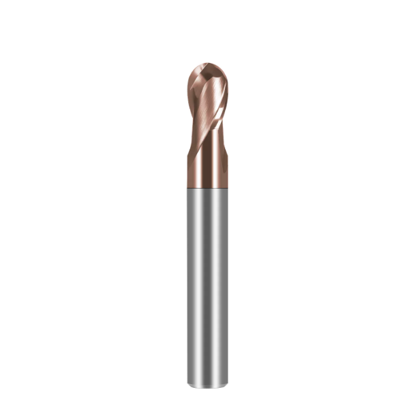
Engineering Secrets in Tool Manufacturing: How High-Performance Carbide Ball Nose End Mills for Hardened Steel Are Made
Years ago, some suppliers treated hard-milling cutters merely as standard tools with a thicker coating—an approach that fails within minutes above 60 HRC. Having spent over fifteen years running CNC grinders and studying metallographic microscopes, we know hard milling generates punishing thermal-mechanical stress fields. Flashy marketing claims cannot hide poor substrate choices or inadequate edge preps under real workshop conditions.
Manufacturing a reliable carbide ball nose end mill requires balancing raw substrate toughness, edge prep micro-geometry, and coating adhesion. A deviation of just a few microns in edge radius or residual grinding stress will expand under high machining temperatures. When that balance fails, the tool suffers sudden catastrophic fracturing rather than steady, predictable flank wear.
0.4μm Nano-Ultrafine Tungsten Carbide Substrate: Tackling 65 HRC Materials
Many buyers assume that choosing the highest Rockwell hardness (HRA) guarantees success in hardened steel. However, pure hardness without fracture toughness leads to brittle failures during interrupted cuts. Common carbide blanks use grain sizes of 0.8 µm or larger; under high load, shear stresses cause micro-cracks to propagate along coarse cobalt pockets, pulling tungsten carbide grains out of the matrix.
Our metallurgical evaluations show that an ultra-fine 0.4 µm tungsten carbide substrate with 10% to 12% cobalt provides the ideal structural balance. The sub-micron grain structure creates massive contact surface area with the cobalt matrix, keeping transverse rupture strength (TRS) above 4,200 MPa while retaining high hot hardness. This engineered substrate ensures our carbide end mill cutter exhibits predictable, microscopic abrasive wear instead of sudden catastrophic fracture.
Edge Preparation Engineering: Measured Differences Between 5μm and 12μm “Waterfall Hone” Chamfers
Machinists often test an edge with their fingernail, believing razor sharpness is ideal, but microscopic razor edges fail instantly above 50 HRC. A freshly ground cutting lip is a fragile wedge under 2 µm thick that breaks the moment it strikes 62 HRC tool steel. In our failure analyses of cutters that chipped on their first pass, nearly 90% lacked appropriate edge preparation.
After grinding on our Walter and Rollomatic 5-axis tool grinders, we apply a controlled 5 µm to 12 µm asymmetric “waterfall” hone. This rounds the cutting edge, redirecting incoming cutting forces into the thicker core of the tool. Combined with holding the complete 220° ball profile tolerance within ±0.005 mm, this hone spreads mechanical loads evenly across the cutting arc, protecting the edge during heavy profile engagement.
Effectiveness of Nanocomposite Coatings (TiAlSiN / AlCrN) Against Delamination in Extreme Dry Machining at 1100°C
When milling steels harder than 50 HRC, our first recommendation is to shut off liquid coolant. Flooding extreme cutting zones creates a vapor barrier that triggers rapid thermal cycling, forming micro-cracks perpendicular to the cutting edge within minutes. Machining hardened tool steels demands dry cutting with cold-air blasts or MQL, backed by high-temperature nanocomposite coatings designed to survive dry friction.
Our dedicated TiAlSiN and AlCrN nanocomposite coatings resist oxidation up to 1,100°C. In the high-temperature zone, silicon and aluminum atoms migrate toward the surface, forming an amorphous nanoscale SiO2 and Al2O3 protective shield. This self-healing boundary layer lowers friction and shields the underlying substrate from heat, keeping the carbide ball nose end mill intact without coating delamination during demanding dry-machining cycles.
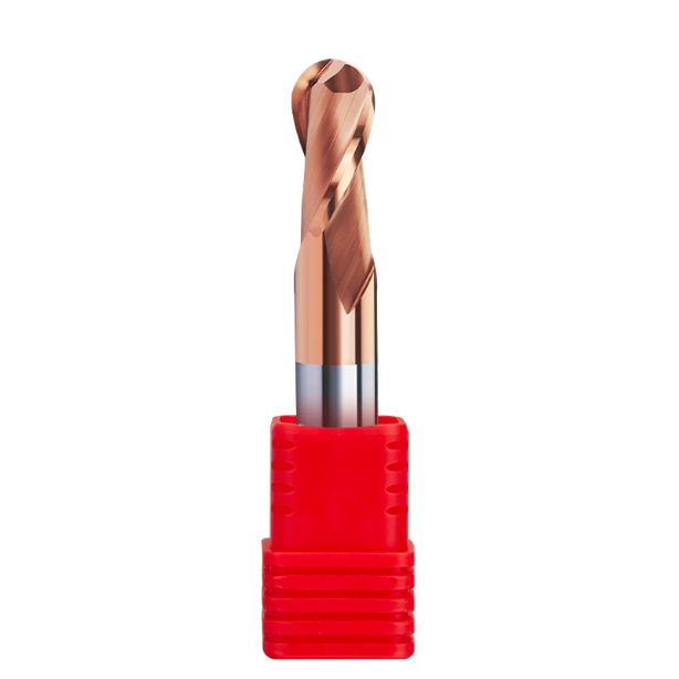
Workshop Machining Strategy: Maximizing the True Service Life of Carbide Ball Nose End Mills via CAM Toolpath Settings
During technical visits to mold shops across the US, we often see the same tool perform reliably for hours in one facility, yet fail in under twenty minutes in another. Hardware differences rarely explain this gap; the real differentiator is CAM toolpath strategy. Many programmers carry over cutting habits from pre-hardened steels into hardened parts, overlooking how sensitive hard materials are to subtle toolpath changes.
No solid carbide substrate or coating can survive sudden radial load spikes or micro-pauses at corner stops. In hardened die cavities, continuous engagement angle control and contact-point surface speed dictate whether an edge wears smoothly or fractures prematurely. Strategic toolpath planning creates a stable stress environment for the cutting edge, which is essential to getting the full value out of any high-performance carbide ball nose end mill.
5-Axis Tool Axis Tilting (Lead/Tilt Angle 10°–15°): Completely Eliminating “Dead Center” Wear
If your machine supports 5-axis simultaneous or positional milling, stop driving the cutter perpendicular to the workpiece. The surface speed at the center tip of a ball nose tool drops to zero by geometric definition. The cleanest way around this physical limit is introducing a 10° to 15° lead or tilt angle in your CAM software. Tilting shifts the contact point away from the dead center to the peripheral flutes, where linear velocity and flute gullet space are optimal.
The machining benefits on the shop floor are immediate. While dialing in a 56 HRC lens mold in Stuttgart, we compared vertical machining against a 12° tilted approach using identical feeds and speeds. The tilted path eliminated center-drag gouging, improving surface roughness from Ra 0.8 µm down to Ra 0.2 µm and cutting bench polish time in half. Eliminating dead-center drag more than doubled the working life of our carbide ball nose end mill for hardened steel.
Trochoidal Milling and Dynamic Constant Tool Engagement for Hardened Steel
Internal corners are the most dangerous zones in any mold cavity. With conventional linear or parallel passes, the radial tool engagement angle spikes from 60° to over 180° the moment the cutter reaches an inside corner. Radial forces jump two- to threefold in milliseconds, which almost always triggers edge breakout in hardened steels. We recommend constant-engagement strategies (such as Dynamic Milling or Adaptive Clearing) with small radial step-overs to cap cutter engagement within safe limits.
Entry moves require the same discipline. Vertical plunging into 50+ HRC steel is a guaranteed way to chip a tool, and ramping angles above 2° remain high-risk. We keep helical entry and linear ramping angles strictly between 1.0° and 1.5°, allowing the cutter to ease into the cut like peeling an apple. Giving the cutting edges time to establish steady thermal equilibrium prevents sudden impact damage to your carbide end mill cutter.
Reference Table for Actual Cutting Parameters (50–65 HRC): Hard Benchmarks for Spindle Speed, Feed, Ap, and Ae
To help programming teams plan stable cycle times, we compiled the baseline parameters below from mold-shop trials across North America. In hard milling, always calculate surface speed (Vc) using the effective contact diameter rather than the nominal tool diameter. The values below reflect 4-flute semi-finishing and finishing cuts; adjust them slightly to match your spindle rigidity and setup stiffness:
| Workpiece Hardness Range | Cutting Speed (Vc, SFM / m/min) | Feed per Tooth (fz, IPT / mm) | Axial Depth (ap) | Radial Width / Step-over (ae) | Cooling Method |
| 50–54 HRC (NAK80, 718H) | 390–590 SFM (120–180 m/min) | 0.0012″–0.0024″ (0.03–0.06 mm) | 0.05–0.10 × D | 0.03–0.08 × D | Air Blast / MQL |
| 55–59 HRC (Hardened H13) | 295–425 SFM (90–130 m/min) | 0.0008″–0.0016″ (0.02–0.04 mm) | 0.03–0.06 × D | 0.02–0.05 × D | Dry High-Pressure Air |
| 60–65 HRC (D2, DC53, CPM) | 195–295 SFM (60–90 m/min) | 0.0004″–0.0012″ (0.01–0.03 mm) | 0.01–0.03 × D | 0.01–0.03 × D | Dry Air (No Flood Coolant) |
When deep pockets force you to pull longer reach tools from your stock of standard ball end mill sizes, scale down surface speed and depth of cut proportionally. The golden rule for milling tool steel above 50 HRC is high spindle RPM, minimal depths of cut, and light, continuous feed rates. High-frequency shearing lets chips carry the heat away—pushing heavy radial chip loads only invites instantaneous tool failure.
Supplier Evaluation and Selection: Criteria for Ensuring Consistent Quality from Professional Carbide Ball Nose End Mill Manufacturers
Throughout this guide, we examined micro-fracture mechanisms, flute selection, overhang deflection, and 5-axis tilt strategies. In production, however, batch-to-batch consistency is the real foundation of success. Process engineers often tell us that an initial tool sample performed well, but the production batch produced dimensional drift or broke without warning. That failure rarely comes from the machine; it points to weak process quality control upstream in the supply chain.
In 50 to 65 HRC milling, tool tolerance margins are virtually zero. A premium carbide ball nose end mill cannot be validated simply by checking shank diameter and overall length with digital calipers. As engineers with over a decade of cutting tool manufacturing experience, we encourage teams to look beyond quoted unit prices. Instead, evaluate suppliers using the same rigor as a formal First Article Inspection (FAIR), auditing profile tolerances, ground concentricity, and raw carbide batch tracking.
H3: Avoiding the Low-Price Trap: Three Key Benchmarks for Evaluating Carbide Ball Nose End Mill Manufacturers
If inconsistent budget tools disrupt your delivery schedules, review your supplier network against three clear technical benchmarks. First, demand proof of ball profile accuracy. Profile precision directly sets the machined scallop height. The entire 220° cutting arc must hold within ±0.005 mm (±0.0002″) of true contour. Ask for a multi-axis non-contact optical inspection report (from systems like Walter Helicheck or Zoller), rather than relying on a single micrometer check.
Second, verify shank tolerances and raw material traceability. Shanks must meet strict h6 tolerance and cylindricity standards; in shrink-fit or hydraulic chucks, micron-level gaps turn into severe centrifugal runout at 20,000 RPM. Finally, inspect the supplier’s carbide batch records for cobalt pooling and stress-relief cycles after grinding. A capable carbide ball nose end mill manufacturer monitors grain size distributions and applies post-grind stress relief, preventing micro-cracks from propagating during the first contact pass.
H3: How to Request a Customized Tooling Solution Based on Your Specific Workpiece Material (NAK80 / Stavax / SKD11 / DC53)
Achieving stable tool life requires matching every element of the tool to your exact steel alloy: sub-micron 0.4 µm substrates, 5 µm to 12 µm edge hone micro-geometry, flute core thickness, and 10° to 15° tool tilt. The abrasive wear caused by massive eutectic carbides in 62 HRC DC53 or SKD11 requires a different geometry than stainless Stavax or pre-hardened NAK80 at 52 HRC, which demand high surface reflectivity.
If you are profiling deep-cavity injection molds and fighting chip packing or tip chipping, send us your part cross-sections and stick-out ratios; we can evaluate whether a reinforced tapered neck is your best fix. If you are struggling to hold surface finishes below Ra 0.4 µm on hardened stamping dies, share your radial cut depths, spindle type, and dynamic runout numbers. Together, we can map out a targeted cutting test—covering CAM tilt angles, feeds, and specialized carbide ball nose end mill for hardened steel micro-coatings built around your exact setup.