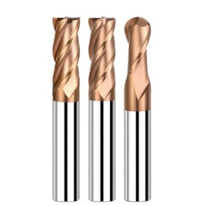
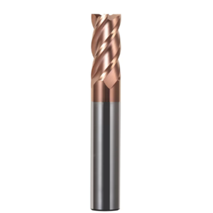
Last month, a long-standing client in Stuttgart reached out with an urgent issue. While machining complex UHMW-PE medical components, they switched to brand-new four-flute cutters. Less than twenty minutes into the run, the edges smeared and melted. Chips fused tightly to the tip, ruining two expensive imported blanks.
We see this shop-floor failure constantly across European and American facilities. Veteran programmers often treat engineering polymers like aluminum or mold steel. They assume that maxing out the RPM with off-the-shelf carbide ball end mills will finish the job.
The reality is completely different. Unlike metals that shear cleanly, plastics react aggressively to heat and mechanical compression. Soft, elastic polymers like PTFE or UHMW behave nothing like abrasive, glass-filled PEEK or carbon-reinforced nylon. They require totally distinct relief angles, flute polishing, and cutting edge preparation.
Grabbing the wrong ball end mill for plastic causes localized melting, stringy burrs, severe tool deflection, or premature tip breakage during corner cleanouts.
We compiled real regrind data and machining feedback to identify the five best tool choices for soft and hard polymers. Before swapping your next cutter, ask yourself one critical question: is your surface melting from poor chip evacuation, or burning because the edge is simply pushing material?

The Fundamental Conflict in Machining Soft vs. Hard Plastics: Why Do General-Purpose Carbide Ball End Mills Often Fail on the Shop Floor?
A common scenario involves an operator running an aluminum part on a 5-axis mill, then switching immediately to polymer plate. Many machinists assume plastics are soft and easy, grabbing standard carbide ball end mills straight from the tool crib. However, general-purpose metal tools feature edge honing and conservative rake angles to survive heavy cutting impacts. Once that edge engages plastic, the material’s low thermal conductivity and low modulus trigger immediate problems.
Our records show over 70% of plastic surface failures stem from this blunt scraping action rather than machine accuracy. Metals generate shear slips where chips carry heat away. Polymers deform elastically under cutting pressure, then quickly spring back against the tool flank. Friction builds up rapidly at the cutting zone. Once temperatures pass the glass transition point, the workpiece shows irreversible whitening, tearing, and smeared surfaces.
From PTFE/UHMW to PEEK/Glass-Fiber Reinforced Polymers: Divergent Requirements for Ball End Mill Edge Geometry
Customers often ask if one cutter can machine every polymer grade. The physical answer is no. Soft polymers like PTFE or UHMW have low melting points and behave like dense rubber under load. Without a dedicated ball end mill for plastic built with high positive rake angles and knife-like sharpness, material piles up ahead of the cut. The edge tears the stock away, leaving heavy, rolled burrs. Relief angles must reach 14° to 16° to clear the elastic spring-back.
Switching to PEEK, PEI, or 30% glass-filled plastics completely rewrites the machining strategy. Glass fibers turn the workpiece into an abrasive grinding wheel. Razor-sharp, unhoned edges dull or micro-chip within minutes, causing severe work hardening. On these abrasive engineering grades, we apply an ultra-fine micro-chamfer to reinforce the cutting edge. Trading away a fraction of sharpness provides the structural rigidity and wear resistance needed to survive.
The Battle Between the Tip’s “Zero-Velocity Zone” and Material Melting Point: A Real-World Case Study of Troubleshooting Plastic Melting on Customer Machines in the US and Europe
Two years ago, we resolved a persistent issue for a medical contract shop in Ohio. The programmer was finish-milling POM-C (acetal) ball joints on a 3-axis vertical mill. A rough patch consistently showed up at the apex of the dome, looking burned and blistered. The operator had increased the spindle speed from 12,000 to 24,000 RPM, which only accelerated the melting. At the dead center of any spherical cutter, the effective cutting diameter drops to zero, meaning zero surface speed.
Plunging straight down causes the tool tip to rub and displace plastic rather than slice it cleanly. We resolved this by modifying the CAM strategy: tilting the tool axis on a 5-axis setup and switching to constant-Z passes rather than bi-directional planar rastering. Shifting contact away from the center dead zone keeps effective surface footage stable. This center-line challenge is why programming a ball nose endmill requires special toolpath attention on deep floor pockets.
Single-Flute/Large-Chip-Space vs. Double-Flute/High-Rigidity Designs: Choosing the Right Carbide Ball End Mills to Prevent Chip Re-welding and Surface Streaking
Machinists often judge tool stability strictly by flute count, but chip clearance matters far more than stiffness when profiling plastics. Ductile plastics produce continuous, ribbon-like chips charged with static electricity that wrap around the tool. High-flute tools trap these ribbons easily. Frictional heat quickly softens trapped chips, re-welding them into built-up edges. For profiling shallow shapes, a single-flute mirror-polished design provides the open clearance required to eliminate streaking.
However, single-flute tools feature smaller web cores, making them susceptible to bending forces in deep corners. When rigidity is mandatory, we transition clients to asymmetric two-flute carbide ball end mills. The two-flute structure provides the core strength needed to resist tool deflection, while unequal flute spacing breaks up harmonic chatter. Balancing flute capacity against core rigidity determines whether you maintain high surface finish or fight tool deflection.

Top 5 Scenario-Based Recommendations: 5 Types of Ball Nose End Mills Specialized for Plastic Contour Milling
When solving complex polymer surface challenges for Western clients, the phrase we dread hearing most is, “Just give me a general-purpose plastic cutter.” Polymers vary wildly in molecular structure, heat deflection temperature, and filler chemistry. There is simply no universal, one-size-fits-all tooling solution for dynamic 3D contours.
We combined tool wear data from contract machine shops with our CNC grinding experience to identify five practical cutter strategies. These match real-world priorities: chip evacuation in gum-like polymers, abrasive wear resistance, micro-feature retention, deep-reach rigidity, and high-volume cycle times. Selecting the right ball nose endmill requires matching tool geometry to material mechanics.
Top 1 (Soft Polymers & High-Gloss Finish): Ultra-Precision Polished Single-Flute Mirror-Finish Ball End Mill for Plastic—Eliminating Burrs on Acrylic (PMMA) and POM
When profiling optical-grade PMMA or tough POM components, the most common shop-floor complaints are edge whitening and torn burrs. Friction on the rake face builds heat rapidly, melting ductile chips against the flute. For these applications, we run a mirror-polished single-flute ball end mill for plastic featuring a high rake angle exceeding 15°. This geometry slices material cleanly with minimal cutting pressure.
However, machinists must respect the structural limitations of a single-flute profile. Thinner web cores and asymmetrical cutting edges limit overall bending stiffness and dynamic rotational balance. We restrict this tool to finish profiling, shallow axial depths, and tight stepovers. Plunging it into deep roughing cuts creates severe tool deflection and risks snapping the cutter inside the part.
Top 2 (High-Hardness, Wear-Resistant Plastics): DLC-Coated Ultrafine-Grain Carbide Ball End Mills—Combating Tool Life Degradation in Glass Fiber-Reinforced (GF) PEEK and PPS
Machining engineering plastics filled with 30% glass or carbon fibers (such as PEEK-GF30) shifts the wear mechanism to severe mechanical abrasion. Field trials at an aerospace supplier revealed that standard uncoated cutters lost their ball nose profile in under thirty minutes, throwing parts out of tolerance. For these abrasive polymers, we rely on sub-micron carbide ball end mills shielded with an ultra-thin Diamond-Like Carbon (DLC) coating.
The solid carbide core delivers critical edge rigidity under load, while the DLC film lowers sliding friction and guards against abrasive erosion. Keep in mind that physical coatings add 1 to 2 microns to the cutting edge radius, slightly reducing razor sharpness. We avoid them on soft, unfilled plastics, but on fiber-reinforced polymers, gaining tenfold tool life outweighs that minor edge trade-off.

Top 3 (Micro-channels and Sharp Corners): Controlling Runout for Micro Carbide Ball End Mills in Medical Microfluidic Chips and Micro-injection Molding Electrodes
Medical microfluidics and sub-millimeter mold details often demand ball end mills with radii under 0.5 mm or down to 0.2 mm. At this scale, even tiny runout creates cutting force spikes that far exceed the tool’s yield strength. When running a micro carbide ball end mill, we instruct technicians to look beyond feed rates and audit spindle-and-holder Total Indicated Runout (T.I.R.) first.
If tool tip runout drifts past 3 microns, the cutter typically snaps the moment it touches elastic stock. We mandate high-precision shrink-fit or hydraulic toolholders and enforce circular ramps or shallow-angle entries over straight plunges. Ramping preserves delicate cutting edges and eliminates chatter marks on critical medical seal surfaces.
Top 4 (Deep Cavities and Steep Sidewalls): Vibration and Deflection Mitigation Using Extra-Long Ball Nose End Mills with Relieved Necks
Deep cavities in automotive light housings and electronic enclosures feature steep sidewalls that standard reach cutters cannot clear. Novice programmers often reach for continuous-diameter long tools, which produce severe chatter washboarding along deep walls. To resolve this, our core approach relies on an extra long ball nose end mill featuring a relieved neck behind the cutting flutes.
Relieving the neck diameter by a few hundredths of a millimeter avoids rubbing along steep walls while keeping the stout shank intact. Remember that long overhangs remain prone to deflection harmonics. We recommend reducing stepover, trimming feed rates, and using 5-axis tool axis tilting rather than pushing heavy roughing passes at full reach.
Top 5 (High-Efficiency Mass Production): Asymmetric 2-Flute Ball Nose End Mill—Balancing Cycle Times in Integrated Roughing and Finishing of ABS/PC Curved Surfaces
High-volume production runs of ABS, PC, and blended enclosures demand the lowest cycle times possible without sacrificing surface quality. Single-flute tools frequently bottle-feed rates, while symmetrical two-flute cutters can trigger harmonic chatter at elevated spindle speeds. In high-output production, we implement a two-flute ball nose endmill designed with unequal flute spacing and differential helix angles.
The asymmetric geometry breaks regenerative chatter frequencies, maintaining stability at elevated feed rates. Two flutes double the feed-per-revolution output over single-flute styles while leaving enough chip space for clearing stock allowance and finish passes. If you switch to gummy materials like soft PE or PTFE, return to a single-flute tool to prevent chip packing.

Specification Selection and Pitfalls: How to Properly Choose Standard End Mill Sizes and Clearance-Oriented Extended Geometries?
Grabbing whatever cutter sits in the tool crib is a recipe for scrap parts. Programmers often look only at corner radii on the CAD model, grabbing an oversized tool for speed or an overly long, skinny cutter to clear tall walls. Unlike metals, plastics deflect under cut pressure and rebound instantly, multiplying dimensional errors caused by cutter push-off.
Most dimensional drift and wavy surfaces we troubleshoot trace back to poor diameter-to-overhang ratios. While selecting off-the-shelf standard end mill sizes keeps tool inventory budgets under control, ignoring the relationship between stepover and scallop height wipes out tooling savings through tedious secondary bench work and part re-inspection.
Balancing Scallop Height with Common Standard End Mill Sizes (1/8″ to 1/2″ and Metric Series) in 3D Plastic Contouring
Balancing imperial (1/8″, 1/4″, 3/8″, 1/2″) and metric (3 mm to 12 mm) cutters requires managing machine cycle time against theoretical surface scallop height. Larger ball diameters produce lower peak-to-valley scallops at identical stepovers. Choosing a tiny 1/8″ tool across broad, sweeping surfaces extends runtimes drastically, while excessive tool reach leaves cyclical vibration ripples in soft polymer stock.
Conversely, large 1/2″ or 12 mm tools have the core stiffness to push feed rates, but their wider cut arcs can overload thin plastic walls in tight concave pockets. We suggest running common standard end mill sizes in staged sequences: use larger tools to smooth broad profiles to a 3–5 micron scallop, then drop down to a smaller tool for corner detailing.
Why we require operators to reduce speeds and switch to 5-axis tilted toolpaths when the overhang exceeds 5×D
When machining deep cavities in polymer housings, overhangs greater than 5× tool diameter (5×D) are routine. Mechanical deflection scales with the cube of unsupported tool length. If an operator runs short-tool speeds on an extended cutter, the tool tip bounces under cutting pressure. Even a high-grade extra long ball nose end mill will leave reverse tapers on deep walls and trigger loud surface chatter.
For long reach set-ups, we reduce spindle speed away from harmonic zones and drop feed per tooth to reduce side loads. When 5-axis or 3+2 positioning is available, tilt the cutter axis 10° to 15° relative to the cut. Tilting moves engagement away from the zero-speed tip dead zone and clears housing shoulders, letting long cutters run chatter-free.
Addressing Root-Clearing with Tiny Radii: Analysis of Tool Breakage Causes for Micro Carbide Ball End Mills (0.2mm–1.0mm) and Helical Entry Guidelines
Miniature ball cutters between 0.2 mm and 1.0 mm are indispensable for micro-fluidic slots, precision gear roots, and small electrodes. Because the core web is thinner than a strand of hair, these tools have low torsional strength. Breakage rarely stems from brittle carbide; our lab evaluations show most failures occur during the first plunge from chip packing and material binding.
Protecting a delicate micro carbide ball end mill requires strict entry rules in the CAM program. Never plunge straight down along the Z-axis. Program a continuous helical entry or an incline ramp under 2°. Ramping gives chips a clear escape path along the flute, protecting the micro-cutting edge from sudden torsional overload.

An Expert Perspective: Parameter Calibration to Maximize the Performance of Ball End Mills for Plastic
Machinists often see high-end cutters underperform immediately after tool setup. A common misconception equates high-speed machining strictly with maxing out spindle RPM and feed rates. In reality, machine dynamic rigidity and servo acceleration must align directly with the cutter’s micro-geometry. Without this dynamic balance, even a premium ball end mill for plastic will fail due to mismatched cutting forces.
When troubleshooting overseas shop floors, our first step is recalibrating the cutting load model rather than swapping tool geometry. Unlike metals, polymers cannot dissipate heat effectively through chips due to low thermal conductivity. Parameter windows are narrower than those for aluminum. Spindle speeds and chip loads must maintain steady chip evacuation without crossing the polymer’s glass transition threshold.
Calculating Effective Cutting Speed (Deff): Dispelling the Misconception That High RPMs Prevent “Material Smearing” at Shallow Depths
Programmers frequently ask why plastic surfaces turn white or smear when running spindles at 24,000 RPM. The issue stems from calculating surface footage using nominal tool diameter. In finish passes with shallow axial depths of cut, the actual contact circle is significantly smaller than the tool’s outer diameter. Standard surface footage formulas yield dangerously inflated numbers.
Factoring in engagement angles reveals that the effective cutting speed (Deff) at the contact zone can drop below 20% of your programmed target. At these low peripheral speeds, the cutting edge plows and extrudes ductile plastic instead of shearing it cleanly. When finishing contours with a ball nose endmill, program CAM-based surface speed compensation or tilt the tool axis to clear the zero-speed tip center.
Practical Comparison of Chip Evacuation Media: Cold Air Guns vs. Water-Soluble Coolants in Preventing Stress Cracking in Plastics
Coolant selection remains a heated topic in plastic milling circles. At an aerospace facility, thick-walled polycarbonate and polysulfone housings were machined using heavy water-soluble coolant. While finishes looked flawless off the table, fine spiderweb micro-cracks appeared across contoured corners within three days. Residual machining stresses combined with fluid surfactants caused severe Environmental Stress Cracking (ESC).
We solved this failure by switching coolant lines to vortex cold air guns. Continuous directional air blasts blast static-charged chips out of deep pockets, preventing chip re-cutting and flute packing. Air also keeps the tool-workpiece interface dry, eliminating chemical stress risks. For stress-sensitive engineering polymers, running filtered cold air with carbide ball end mills is the most reliable process choice.

Procurement and Supply Chain Vetting: How to Identify a Carbide Ball End Mill Supplier with Genuine Engineering Expertise?
Process planning can look perfect in CAM simulation, but tool-to-tool manufacturing variation quickly ruins production runs. In multiaxis contour milling, the cutter serves as the primary datum for the entire dimensional chain. If a vendor grinds plastic tools to standard metal-cutting tolerances, slight profile variances between batches will destroy programmed cusp height consistency.
A reliable partner understands the mechanics of polymer deflection, electrostatic chip clearing, and thermal limits. A qualified carbide ball end mill supplier discusses material responses under load and provides clear tolerances for micro-grain carbide, flute polish, and edge prep. They evaluate the machining environment rather than pushing generic catalog numbers.
Verifying Supply Consistency: How Professional Carbide Ball End Mill Suppliers Control Ball-Nose Radius Accuracy (±0.005mm) and Edge Honing
Ball-nose form accuracy governs blend quality across overlapping 3D toolpaths. Standard metal mills often allow radius deviations of ±0.01 mm or higher, but a 5-micron error leaves noticeable mismatch steps on plastic optical surfaces. A precision carbide ball end mill supplier must verify the ball arc on 5-axis CNC grinders using in-process lasers or optical interferometry, guaranteeing form tolerances within ±0.005 mm across batches.
Microscopic edge preparation is equally critical. Abrasive glass-filled polymers require a light, uniform micro-hone to reinforce cutting edges against chipping. Unfilled soft polymers, however, demand unhoned, razor-sharp edges ground directly from fine-grit wheels. Inspecting incoming shipments under magnification confirms that the cutting edge matches your polymer’s specific shearing mechanics.
Standard Stock Sizes vs. Custom Non-Standard Tools? Cost-Reduction Inventory Strategies for European and American Job Shops
Job shops balancing high-mix part schedules struggle with tool inventory overhead versus custom lead times. Rushing complex parts with general-purpose tools raises scrap rates, while waiting on special tools delays delivery. We advise a tiered crib strategy: use off-the-shelf standard end mill sizes for roughing, planar surfacing, and shallow 3D profiles to leverage volume pricing and standardized CAM libraries.
When facing deep vertical walls, micro-fluidic channels, or strict surface finish callouts, off-the-shelf profiles fall short. If you are battling chatter in deep cavities, consider custom necked-down shanks for clearance. If you are preparing a high-volume polymer run, sharing your component models, resin datasheets, and machine spindle specs allows us to collaborate directly on an optimized tooling layout.