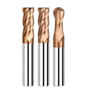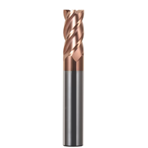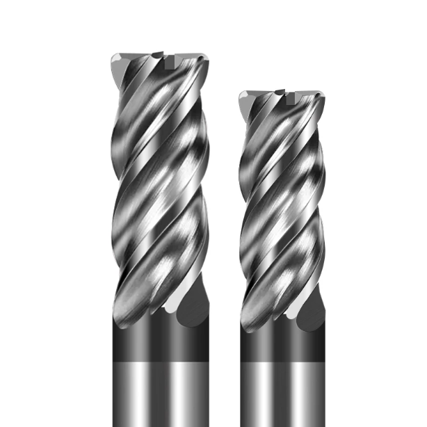
Last month, the technical director at an Ohio machine shop sent us a troubling video. They were slotting 316 stainless flanges on a horizontal machining center when the spindle pitch suddenly bogged down. By the fourth part, the tool tip sheared right off. He was baffled: “Last week on the exact same machine, we ran 304 valve bodies with a 1/2-inch tool and easily hit 18 parts per edge. Why did switching to 316 kill the cutter in under two hours?”
In our fifteen-plus years of tool manufacturing and on-site support, we see this exact nightmare play out monthly across US machine shops. Programmers frequently treat 304 and 316 as identical “300-series stainless,” copying and pasting the exact same tool paths and speeds. But under the toolmaker’s microscope, their chip flow and crystal deformation tell two entirely different stories. Overlooking these microstructural differences usually turns your shop floor into an expensive scrap yard.
The true killer in 304 is rapid work-hardening; a sharp corner creates a glazed hard skin on the cut surface, causing heat buildup and catastrophic chipping. In contrast, 316 packs 2% to 3% molybdenum, doubling high-temperature tensile strength and causing gummy chips to weld onto the tool edge. Cutting forces spike in milliseconds, destroying tool tips through severe notch wear.
In both materials, tool life rarely hinges on holder rigidity alone. Instead, it relies on a micro-geometry feature that CAM programmers often overlook: the end mill corner radius for stainless steel. Sharp square ends cannot dissipate shear stress, while oversized radii drive up radial forces and trigger violent chatter. If your parts show torn surface finishes or blown-out corners, your 304 radius is likely killing your 316 cycle.
Is the corner radius in your carousel right now truly matched to your alloy?
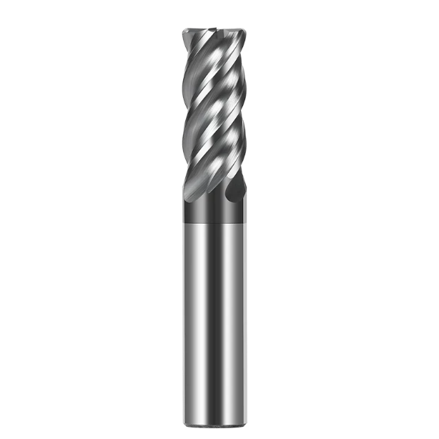
Why Can’t the Choice of End Mill Corner Radius Be the Same for 304 and 316 Stainless Steel?
Many shop supervisors view 304 and 316 as interchangeable austenitic stock, applying identical tool specifications to both. But across hundreds of field setups, we have seen that their shear resistance and chip formation mechanisms act completely differently. Simply put, cutting 304 tests your tool edge against crushing impact and deformation heat, while 316 attacks your cutting edge with thermal galling and violent abrasive tearing.
Blindly copying your 304 tool geometry over to 316 rarely results in gradual flank wear. Instead, you get immediate edge flaking and tool failure. Finding the sweet spot for an end mill corner radius for stainless steel is never a one-size-fits-all formula. You must balance chip evacuation clearance, side-deflection forces, and thermal dissipation area to hold tolerance across the entire run.
Managing 304’s Intense Work-Hardening: Using Corner Radius End Mills to Combat Heat Concentration and Micro-Chipping
A few years ago, we helped a Texas valve maker eliminate catastrophic tool failure in deep 304 valve cavities. They ran conventional square end mills, but by the third part, the sharp corners turned white-hot and chipped apart. Plastic deformation transforms 304’s austenite into hard martensite. A sharp, unsupported square tip essentially hammers against this work-hardened shell until the carbide fractures.
Our fix was immediate: keep the same surface footage and chip load, but swap the square tool for a corner radius end mill with an R0.5 (0.020″) radius. This small arc redistributed the thermal spike along a smooth curve, converting abrupt impact into an angled shearing force. Tool life jumped from 3 parts to 8 parts per edge, and sidewall chatter disappeared. Adding a corner radius provides the mechanical cushion 304 demands.
High Adhesion and Tensile Strength of 316 Stainless Steel: Solving Notch Wear with Carbide Corner Radius End Mills
Machining 316 is a completely different game. The molybdenum addition boosts high-temperature shear strength and chemical affinity, turning the material extremely gummy. In our sharpening facility, returned cutters frequently show deep pits at the depth-of-cut line—the classic signature of depth-line notch wear. Chips weld to the cutting edge under intense pressure, pulling microscopic carbide grains along as they break free.
To counter this destructive adhesion, we steer machinists toward a premium carbide corner radius end mill running low runout and a larger radius. A larger corner arc thins the chip, allowing gummy 316 chips to curl cleanly away without concentrating heat on a single spot. Keep the radius between R1.0 and R1.5 (0.040″ to 0.060″) with high-pressure coolant; this controls radial push while stopping notch wear before it starts.
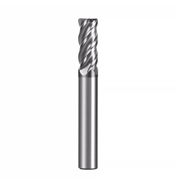
The Trade-off Between Flute Count and Chip Evacuation: Real-World Performance of 4-Flute Carbide Corner Radius End Mills vs. 2-Flute Tools
Many machinists assume that when milling stainless steel, higher flute counts are always superior due to higher table feeds and stiffer cores. But cutting stainless is a constant tug-of-war between core strength and gullet capacity. Stainless alloys produce stringy, continuous chips that pack tight channels rapidly. If your flute fills with chips, even the toughest tool snaps in milliseconds from thermal shock and chip packing.
When setting up jobs, we evaluate the openness of the cut above everything else. Profiling an open boss requires completely different chip space than slotting a deep pocket. Choosing a 4 flute carbide corner radius end mill over a 2-flute tool is not about brand preference; it comes down to balancing cross-sectional rigidity against the chip volume needed to safely clear sticky swarf.
4-Flute Carbide Corner Radius End Mill: A Balanced Choice for Stainless Steel Deep-Cavity Side Milling and Profile Finishing
For deep sidewalls or thin-walled profiles, a 4-flute design is our standard workhorse. Last year, a medical shop in Minnesota struggled with deep internal walls on 304 stainless housings. Their standard equal-pitch mills left heavy chatter marks around Ra 1.6. In tall sidewalls, tool deflection and harmonic resonance ruin finish, while the larger core of a 4-flute tool resists that radial push.
We resolved this by switching to an unequal-helix 4 flute carbide corner radius end mill running an R0.5 (0.020″) corner radius. The variable geometry broke harmonic cycles, cutting radial chatter by nearly 70% and pulling finishes down to Ra 0.4–0.6. The bottom radius prevented localized corner wear. If you need square sidewalls without tool taper, a chatter-resistant 4-flute corner radius tool is your best bet.
2 Flutes End Mill Corner Radius: Solutions for High-Viscosity 316 Stainless Steel (Wide-Step Slotting & Micro-Hole Plunge Milling)
When an operation shifts to full-width slotting (100% Ae) or aggressive helical plunging, high flute counts become liabilities. A Wisconsin shop recently tried slotting 1.5xD deep in 316 stainless with a 4-flute tool. Even under flood coolant, the tool snapped in under four inches. Gummy 316 chips welded inside the shallow flutes instantly, causing catastrophic tool breakage from chip packing.
In tight slots, we routinely step down to a 2 flutes end mill corner radius. The deep, parabolic flutes clear thick 316 chips before they expand, preventing chip recutting entirely. Meanwhile, the corner radius reinforces the tip during steep ramp angles. Sacrificing a bit of feed rate to run a 2-flute tool ensures continuous, lights-out reliability when digging out deep slots.
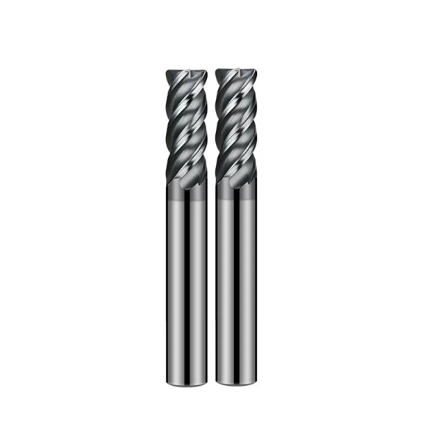
From Standard to Non-Standard: What Are the Limits of Standard End Mill Corner Radii?
Standard catalog corner radii dominate distributor shelves for good reason. They offer a reliable middle ground between tip toughness and part compatibility. But grabbing whatever radius is on hand often causes trouble. Operators end up with blown-out tool tips on heavy cuts or severe wall taper during light finishing passes.
Knowing when to leave the safety of a standard end mill corner radius is a trade-off between tooling cost and scrap risk. Off-the-shelf radii handle roughly 80% of common jobs easily. But when tight internal radii or deep overhangs enter the picture, forcing a standard radius on the cut leads to bad finishes, poor tool life, and costly cycle interruptions.
Mechanical Performance of Common Standard End Mill Corner Radius (R0.5, R1.0, R2.0) Across Different Machining Depths
A corner radius does much more than strengthen the edge; it redirects cutting forces. Dynamometer testing shows that an R0.5 tool keeps cutting forces predominantly radial (horizontal). That behavior suits shallow radial cuts at higher feeds. But when you step up to an R1.0 or R2.0 radius, the larger contact arc redirects cutting pressure upward into the spindle.
Directing force along the Z-axis is crucial for suppressing chatter during deep-reach milling. Spindles are much stiffer axially than radially, so this shift minimizes tool deflection. However, on light machines or thin-floor parts, an R2.0 standard end mill corner radius can generate too much downforce, flexing the workpiece floor. Always check your setup rigidity before bumping up radius size.
When Drawings Strictly Mandate Radii Below R0.2: A Compromise Strategy to Prevent Overheating and Chipping of “Pseudo-Sharp” Carbide Corner Radius End Mills
Aerospace drawings often call out tight internal fillets under R0.2 (0.008″). Machinists often run sharp micro-radius tools to clear them, but in stainless, tiny radii behave like “pseudo-sharp” edges. When the corner radius is thinner than the undeformed chip, metal smears instead of shearing cleanly. We saw this in Europe on 316 airframe brackets, where tools burned out on part two due to 900°C friction spikes.
To clear tight prints without breaking tools, we grind a custom carbide corner radius end mill with an 8-to-12-micron micro-hone. This edge prep supports the carbide crystal structure under extreme shear heat. We then clear the pocket with an R1.0 tool, leaving just 0.05mm (0.002″) of stock for the micro-radius cutter. Honing the edge and minimizing radial stock is the only way to run tight radii reliably.
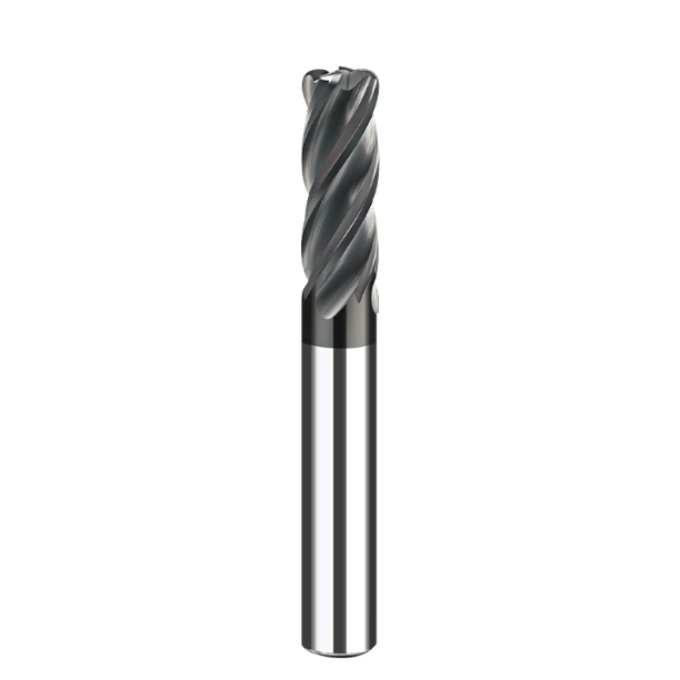
Practical Calibration of Cutting Parameters: Feed Compensation Pitfalls for Corner Radius End Mills in 304 and 316 Stainless Steel
Many programmers blindly copy catalog speeds and feeds into their CAM software, post the code, and hit cycle start. In our shop, catalog parameters represent an idealized baseline, nothing more. A static mindset destroys tooling in stainless; along the corner arc, the true undeformed chip thickness and thermal load shift non-linearly with toolpath engagement. Rigidly adhering to static formulas leads straight to chipped flutes and scrap parts.
This dynamic is especially punishing when jumping between 304 and 316 stainless, where thermal conductivity is notoriously poor. Running a corner radius end mill requires active defense against internal corner over-engagement, while adjusting for strain-hardening and chip galling. Knowing precisely when to back off linear feed rates along complex contours is what separates seasoned machinists from button pushers.
Arc Feed Adjustment in CAM Programming: Prevent Overloading Your 4-Flute Carbide Corner Radius End Mill
A classic programming oversight is ignoring the velocity difference between the tool centerline and the outer cutting periphery during internal arc interpolation. We resolved this on a 304 turbo manifold job in Michigan, where end mills burned out exclusively in pocket corners. The machine control calculated programmed feed at the tool center. When interpolating tight internal radii, the cutter’s instantaneous radial engagement doubled in milliseconds.
That sudden spike crushes a 4 flute carbide corner radius end mill. Compact flute gullets choke on the oversized chip, trapping shear heat and fracturing the corner radius under excessive load. We fixed this by enabling CAM corner deceleration, dialing back linear feed by 40% to 60% before arc entry. Adding two seconds to a pocket cycle eliminated tool blowouts and kept spindle uptime steady.
Empirical Data on Cutting Speed (SFM) vs Tool Nose Radius Life for 316 Stainless Steel
Backing off speed by 10% when switching from 304 to 316 is never enough to save your cutter. Our tool testing data maps a steep failure curve: a 1/2-inch R1.0 mill runs comfortably at 280–320 SFM in 304. But in 316, where molybdenum hardens the shear plane, pushing beyond 210 SFM triggers a steep drop in tool life as notch wear shreds the corner radius.
We enforce a strict 316 derating rule on the shop floor: pull surface footage down by 25% to 35%, pinning it at 180–200 SFM. If running a smaller carbide corner radius end mill, back off your feed per tooth (fz) another 15% to clear the glazed work-hardened skin safely. Dropping surface footage prevents runaway thermal breakdown, saving hours of resetting offsets and scrapping expensive test forgings.
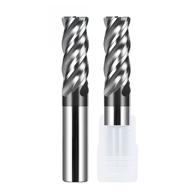
A Guide for Procurement Managers and Engineers: How to Evaluate Qualified Corner Radius End Mills Suppliers
Over fifteen years in tool fabrication and regrinding, we have watched job shops bleed money on low-bid cutters. Purchasing agents often compare outer diameter, overall length, and unit price, rarely inspecting the corner under an optical comparator. The corner radius endures the heaviest thermal shock and mechanical shear; tiny flaws from inconsistent grinding wheels turn into ruined surface finishes and scrapped parts.
Vetting qualified corner radius end mills suppliers comes down to auditing profile repeatability and batch consistency. If your shop fights batch-to-batch tool life swings or has to touch off every replacement cutter to chase taper, look past piece price. Inspect grinding wheel dressing quality, blend-point tangency, and coating bond integrity before signing off on volume tooling POs.
Say No to Subpar Quality: Quality Control Benchmarks for Corner Radius End Mill Suppliers Regarding Tip Radius and Tangency Tolerances
The truest test of a grinding department is the blend point where the corner radius meets the peripheral flute. Inferior 5-axis tool grinders often leave a micron-sized step or under-cut right at that intersection. In mild carbon steel, that ridge might rub away unnoticed. In work-hardening 304 or gummy 316, that seam catches chips, leaves ugly witness lines on sidewalls, and sparks premature flank chipping.
This is why we demand strict blend-point continuity when auditing corner radius end mills suppliers. In our grinding facility, corner profiles are held inside a tight ±0.005mm envelope and verified at 100x optical magnification. If your operators are chasing dark witness lines on precision floor-to-wall transitions, check your tools under a scope; an unblended step at the tangency point is almost always the smoking gun.
Coating Adhesion and Substrate Hardness: Key Criteria for Selecting Carbide Corner Radius End Mills Resistant to High-Temperature Stainless Steel Shearing
Beyond geometry, the interface between substrate and coating determines whether a tool survives severe stainless shear zones. Bargain tools frequently rely on generic single-layer AlTiN coatings that delaminate rapidly under 316 thermal shock. Premium endurance demands multi-layer AlCrN or silicon nanocomposite coatings rated past 1100°C, which form a lubricious aluminum-oxide barrier directly at the chip-tool contact interface.
When sourcing a carbide corner radius end mill, use a 20x loupe to inspect the flank coating; subpar PVD runs look dull with coarse droplet spatter, while elite coatings show a flawless, slick sheen. If you are ramping up a tough stainless program, send over your part print, machine specs, and current parameters. We can look at the application as machinists to dial in the ideal flute count, corner radius, and toolpaths.