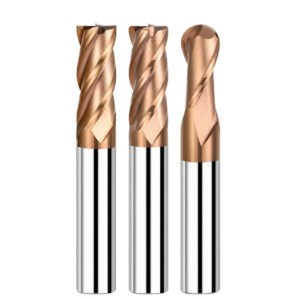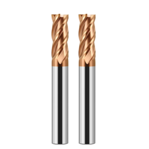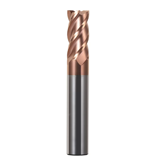
Last month, a good friend running an automotive mold shop in Germany emailed us to vent his frustration. He was machining 1.2379 (D2) stamping inserts heat-treated to HRC 54. Using off-the-shelf tools for 90-degree square shoulder milling, the cutting tips chipped into jagged teeth before even finishing half a shift. The cavity walls ended up with heavy deflection steps. The downtime to change tools and reset work offsets wiped out almost 30% of that job’s margin.
We see this exact bottleneck all the time in our technical support tickets and shop-floor visits. When machining steels between HRC 45 and 65, many programmers fall back on the same old assumptions: pick any solid carbide tool, dial down the RPM, and drench the cut in flood coolant. This approach almost always ends in broken tools. High shear forces destroy weak cutting edges within seconds, and 90-degree corners lack the natural structural support found on ball-nose or radius tools.
Milling true 90-degree square shoulders in hardened tool steel demands far more than just picking a high hardness rating on a label. Success comes down to micro-geometry. You must balance sub-micron tungsten carbide grain size, cobalt binder ratios, and high-heat PVD coatings. Choosing the right square milling cutter for hardened steel also requires proper negative rake angles and controlled edge honing. Without these, your tool will snap before reaching its second hour.
Are you constantly fighting corner chipping and tapered sidewalls on hardened tool steel? Before you adjust your feeds again, take a close look at the tool in your spindle. Is your current square milling cutter genuinely engineered for high-hardness materials?
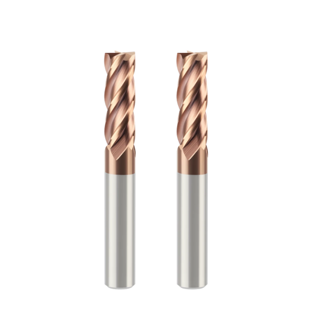
Why Edge Chipping Occurs in Hardened Steel (HRC 45–65): Shop-Floor Realities
Walk into any machine shop, and you will hear operators complain about fresh tool tips chipping on their first passes. Machinists usually blame soft carbide grades or weak machine iron. But when we put inspection scopes on broken cutters and check spindle load curves, physics tells a different story. Hardened steel has extreme yield strength and a tiny shear angle, focusing extreme heat within 0.1 mm of the cutting edge.
Under these loads, material removal shifts from clean shearing to micro-plastic extrusion. High unit cutting forces hammer the cutting edge with rapid shock loads. If heat cannot escape with the chip, the cobalt binder softens instantly. The carbide grains lose their bond, leading to thermal fatigue and sudden chipping rather than normal flank wear.
Failure Analysis: Why a Square Milling Cutter for Hardened Steel Loses Corners First
Inspect a worn tool, and you will see shiny side flutes but completely shattered corners. Unlike ball-nose or bull-nose geometry, a 90-degree corner lacks a gradual stress dissipation path. It carries the highest mechanical load with the smallest thermal mass. When a square milling cutter for hardened steel hits an inside corner, the radial engagement angle triples instantly. That sudden spike in cutting resistance fractures unprepared corner points right away.
Deep shoulder profiling carries equal risk. Machinists often run full-depth side cuts to save cycle time on hard cavity walls. This cut geometry magnifies radial push-off forces at long gauge lengths, creating high-frequency chatter. The corner hammers against the work-hardened wall, strips the coating, and shatters the brittle carbide substrate. A reinforced corner protection chamfer and controlled edge hone protect the tool far better than razor sharpness.
Old Habits Fail: Misconceptions When Using a General-Purpose Milling Cutter on Hard Steels
Machinists switching from pre-hardened steels (like P20 or 1045) often carry over their old habits. They assume that backing off spindle speed and drenching the part in coolant lets a standard milling cutter survive. In reality, that rule of thumb fails once material hardness crosses HRC 50.
Coolant abuse and poor chip thickness control cause most premature failures. Flooding cold emulsion over an 800°C cutting edge causes thermal shock on every tool revolution. This rapid heating and cooling cycle triggers vertical comb cracks along the cutting edge, causing the flutes to snap off. Furthermore, dropping chip load too low causes severe rubbing instead of cutting. The tool burns a work-hardened glaze into the steel, ruining the next pass immediately.
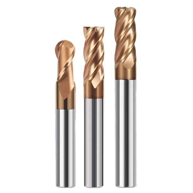
Tool Body Substrate and Micro-geometry: Critical Selection Parameters for Long-Life Carbide Milling Cutters
When inspecting abnormal wear on a customer’s machine, we look at the cutting edge under a microscope before touching any feed dials. Machining hardened steel is a brutal contact battle between the tool edge and a hard martensitic matrix. Instability rarely stems from CAD/CAM toolpaths alone. Instead, it traces back to weak carbide metallurgy or the wrong edge preparation.
Selecting durable carbide milling cutters requires ignoring peak hardness ratings on sales brochures. Transverse rupture strength (TRS) and hot hardness are in constant tension. Finer tungsten grains boost wear resistance but drop fracture toughness, while cutting cobalt too low causes instant brittle fractures. You must balance grain size, cobalt binder content, and rake geometry to survive intense cutting zones.
Practical Pairing of Sub-micron Carbide and High-Heat-Resistant PVD Coatings
Machinists often ask us if the hardest, finest carbide grade is always best. The real answer depends entirely on impact load. For hardened die steels between HRC 50 and 60, we specify sub-micron substrate stock with 0.4 to 0.6 µm grain sizes and 8% to 10% cobalt. This specific blend maintains high red hardness while preserving enough toughness to prevent the tip from shattering like glass over hard spots.
Once the substrate is locked in, a premium PVD nano-coating shields against dry cutting heat above 1,000°C. We strictly avoid legacy coatings thicker than 4 microns, as heavy coatings dull cutting edges and trap internal stresses. Modern nano-layered PVD coatings like AlTiSiN or AlCrN work best here. They form a slick aluminum-oxide barrier at speed, keeping extreme heat away from the vulnerable carbide core.
Negative Rake Angle and Edge Honing Design for HRC 50+ Materials: Preventing Micro-chipping on Square Milling Cutter Edges
Machinists accustomed to aluminum often think a hard-milling square end mill feels dull right out of the box. But that geometry is intentional. A sharp, positive-rake knife edge cannot support the brutal shear stress of hardened tool steel. When grinding a high-performance square milling cutter, we use a negative radial rake of -5° to -10° to back the cutting wedge with solid carbide mass.
Rake angle alone cannot save the corner; edge honing makes or breaks the tool. An unprepared razor edge chips out within seconds of contact. We apply controlled micro-blasting to produce a consistent 0.015 to 0.025 mm edge radius. Adding a tiny corner protection chamfer spreads cutting forces across a 3D bevel, eliminating corner blowouts during shoulder clearing.
Why the Balance Between Chip Evacuation and Rigidity Determines Success: Choosing Between 2-Flute and Multi-Flute (4–6 Flute) Cutters
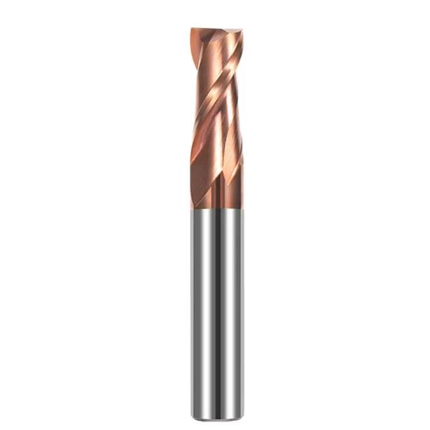
Flute count often sparks fierce debate between milling operators. Traditional two-flute designs feature massive chip pockets for unrestricted chip flow. They remain our top choice for full-slotting, aggressive plunging, or clearing chips out of narrow blind cavities. When running a 2 flute milling cutter, you never have to worry about chips packing the flutes and snapping the tool.
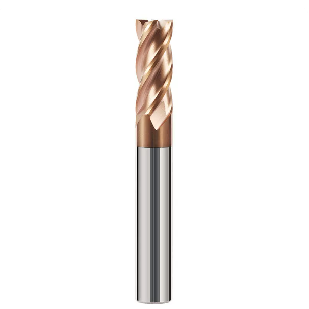
However, hard milling produces tiny, dust-like chips rather than thick curls. Deep flutes only weaken the tool core and cause severe chatter. In materials above HRC 45, we shift to 4-flute or 6-flute end mills for side milling. Multi-flute tools increase core thickness to over 65% of the cutter diameter, delivering massive rigidity and allowing much higher table feeds.
Matching Specifications with Rigidity: From Standard Milling Cutter Sizes to Deep-Cavity Machining Strategies
Tool carousels often hold a chaotic mess of end mill lengths, yet scrap rates climb when finishing deep cavities. Operators routinely grab any cutter that reaches the floor without checking deflection math. Deflection follows cantilever beam physics: deflection scales with the cube of overhang length, but drops with the fourth power of cutter diameter.
Adding just 2 or 3 mm of unneeded stick-out to clear a clamp destroys tool stiffness. When cutting hard tool steel, that extra length causes exponential tool tip deflection. Standardizing your standard milling cutter sizes and keeping length-to-diameter (L/D) ratios tight does more than clean up tool cribs. It creates a rigid setup that stops wall taper and chatter before they ruin your tolerances.
Standard Milling Cutter Selection: Balancing Corner Radii with Tool Overhang Rigidity
When evaluating customer programs, we constantly see programmers picking an end mill that matches the print’s inside radius exactly. For an R3 mm inside corner, operators routinely program a standard Ø6 mm flat end mill. As the tool hits the corner apex, radial engagement surges from 15 degrees to a full 90-degree wall. That shock load hammers the tool and snaps cutting corners.
A smarter, stepped strategy saves your tools. First, use rigid, larger standard milling cutter sizes like Ø10 mm or Ø8 mm to rough and semi-finish the cavity. Then, drop down to an undersized cutter, like Ø5 mm, for the inside corners. This size gap gives CAM software room to roll the tool smoothly through the corner, preventing shock loads and multiplying tool life.
Troubleshooting Micro-Corner Clearing: Preventing Breakage of Ø2mm Micro-Cutters in Deep Cavities
Machining medical bone plates or mold cores requires micro-tooling for small details and ribs. When milling steel past HRC 52, the margin of error for a 2mm milling cutter is measured in single microns. These tiny tools have negligible cross-sectional mass. A few microns of spindle runout will overload a single tooth and snap the neck instantly.
To keep micro-tools running reliably, keep total indicated runout (TIR) under 0.003 mm (3 microns) at the tool tip. Always choose short-flute tools (1.5D to 2D) with reinforced 4 mm or 6 mm shanks and tapered necks. Never plunge straight down into hard steel; ramp in smoothly using a helical motion under 1.5 degrees to protect the micro-flutes.
Suppressing Tool Deflection and Chatter at Overhangs Exceeding 3D: Measured Impact of Toolholder Systems
When cavity depth forces your tool overhang beyond 3D or 5D, cutting instability rarely starts at the tool flutes. It starts at the spindle interface. Many shops still run standard ER collets on hardened steel, leading to micro tool pull-out and fretting corrosion. Long overhangs demand high-rigidity toolholding to eliminate runout and vibration.
Our testing proves shrink-fit and hydraulic chucks each have specific sweet spots. Shrink-fit holders deliver exceptional concentricity and a slim profile for tight drafts at speeds above 15,000 RPM. But for deeper cuts with interrupted shock loads, hydraulic holders win. Their internal fluid bladder dampens vibration, stopping chatter before it flakes the edges off your carbide square cutters.
When Standard Tools Fall Short: When Switching to Custom Milling Cutters Cuts Costs and Boosts Efficiency
In high-volume machine shops, we often see operators modify off-the-shelf end mills on manual bench grinders just to clear deep walls. Other times, they run tools with extreme overhang, crawling at slow feeds while enduring harsh chatter. This seems to save upfront tooling costs. However, scrapped parts, secondary bench polishing, and lost spindle time quickly make it an expensive compromise.
Standard catalog end mills are compromises made for general tasks. Once workpiece hardness crosses HRC 55, zero-clearance cavities leave no room for excessive tool deflection. When wall chatter spikes, cycle times stall, or witness marks cannot be polished out, purpose-built custom milling cutters become the most cost-effective way to protect part margins and cycle times.
Mold Cavity Clearance and Non-Standard Neck Lengths: Using Custom Milling Cutters to Eliminate Re-clamping and Tool-Pass Marks
Deep stamping dies and die-cast cavities often feature tall, vertical walls with tight bottom radii. Running a standard long-flute cutter causes redundant side flutes to rub against the finished wall. Trapped chips score the cavity, leaving deep scratch marks. On the other hand, stepping down with multiple short tools creates noticeable mismatch lines at every transition due to heavy cutting forces.
We solve this deep-pocket problem by engineering specific relieved necks and reinforced tapers. With engineered custom milling cutters, we shorten the cutting flute to a rigid 1.5D to 2D length while grinding 0.2 mm to 0.5 mm of radial neck clearance above it. This design prevents side rubbing, eliminates tool push-off, and cleans the bottom corner in a single setup without manual bench polishing.
Customizing Composite Chamfering Edges and Unequal Flute Spacing: Solving Cycle-Time Bottlenecks in Mass-Producing Hardened Molds
High-volume production lines lose valuable minutes when swapping tools between milling and deburring. The conventional sequence uses a flat end mill for corner clearing, followed by a separate chamfer tool. In steels above HRC 50, this extra tool change wastes tool carousel pockets and introduces contour alignment errors between passes.
Combining features into a single tool eliminates these setup bottlenecks. We grind the bottom square edge and a top chamfer angle onto one continuous carbide blank, creating a burr-free square corner and bevel in one pass. To stop regenerative chatter in hard steel, we also incorporate unequal flute spacing and variable helix angles. These varied flute geometries break harmonic vibrations, keeping the cut quiet at aggressive feeds.
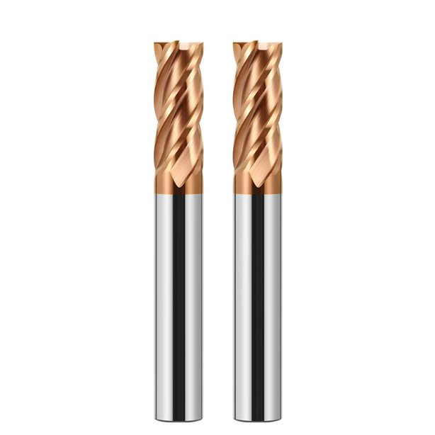
Shop-Floor Parameters and Toolpath Strategies: Doubling Square Milling Cutter Life in Hardened Steel Machining
Even a perfectly ground cutter will chip quickly if your CNC programming relies on legacy milling habits. Hard milling requires tight coordination between tool geometry, CAM toolpaths, and the cooling medium. The edge strength built into a premium square milling cutter only works if the toolpath avoids sudden shock loads in corner dead zones.
Extending tool life in hardened tool steel comes down to managing heat transfer and maintaining a constant chip load. Many shops run low spindle speeds and shallow axial step-downs, assuming gentle passes protect the tool. In HRC 45+ materials, that approach rubs the tool to death. You must convert cutting resistance into manageable shear heat, then evacuate that heat inside the ejected chips.
Implementing High-Speed Trochoidal (HEM/Dynamic) Toolpaths: Feed Rates and Chip Thinning Compensation with Large Ap and Small Ae
Traditional 90-degree corner paths spike radial tool engagement instantly, chipping tool corners. Switching your CAM programming to dynamic trochoidal or high-efficiency milling (HEM) paths eliminates these shock loads. This strategy utilizes the full flute length with deep axial cuts (Ap of 1.5D to 2D) while restricting radial step-over (Ae) to just 5% to 10% of the cutter diameter. Short radial engagement keeps the cut time down to milliseconds, carrying heat away in the chips.
However, running a shallow radial cut creates severe chip thinning. When radial width drops below the tool radius, the actual chip thickness falls far below your programmed feed per tooth. If you fail to compensate, the edge rubs the steel, causing severe work hardening. You must raise your table feed rate on the CNC controller to maintain a chip thickness larger than the hone radius, keeping the flutes cutting cleanly.
Avoid Blind Use of Coolant: How Air Blast and MQL Chip Clearing Eliminate Thermal Cracking Risks in Carbide Milling Cutters
Flooding high-pressure coolant over a cutter running hard steel is a recipe for broken flutes. The cutting zone rapidly hits 800°C on engagement, then gets quenched by cold coolant every revolution. At high spindle speeds, this creates extreme thermal shock cycles every second. These rapid temperature swings generate comb-like thermal cracks across the edge, causing premature failure in high-grade carbide milling cutters.
Dry milling with a high-pressure air blast remains the most reliable strategy for hard milling. Dynamic air pressure blows hot, abrasive chips out of the pocket before they can be recut. If your sidewall finish demands lubrication, apply a light air-oil minimum quantity lubrication (MQL) mist to reduce friction without causing thermal shock. If you are struggling with chipped corners, taper, or low tool life on hardened steels, share your part drawings and parameters with us; we can review your cutting forces and help you dial in the right tool and toolpath for your machine.