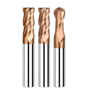
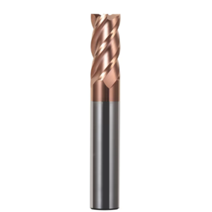
Last quarter, our technical team assisted an Ohio precision die shop setting up an insert run. The workpiece was pre-hardened H13 tool steel (heat-treated to HRC 55–58) with deep cavities and tight transitional profiles. The machine operator habitually loaded a standard square tool to clear the bottom corners. Less than ten minutes in, a piercing screech signaled catastrophic failure: the zero-radius tip shattered, gouging the wall 0.15 mm deep and nearly scrapping a multi-thousand-dollar mold core.
We see this costly failure mode constantly while supporting mold shops across North America and Europe.
Many programmers assume hardened steel is tough solely due to high yield strength, thinking lower feed rates will let them power through. However, the fatal flaw of sharp-cornered cutters is the geometric singularity at the tip. Cutting forces and shear heat concentrate instantly onto that microscopic point. Switching to a rigid corner radius end mill disperses those resultant forces across an arc, stopping the cycle of micro-chipping, thermal cracking, and sudden edge blowout.
Making that radius perform on the shop floor requires dialed-in parameters and tooling choices:
- Substrate grain size and fracture toughness: For hard, brittle blocks, our carbide corner radius end mill blanks prioritize high transverse rupture strength over raw hardness to survive severe interrupted cuts.
- Thermal endurance in extreme-hardness milling: Milling steels near HRC 60–65 (like DC53 or CPM-10V) requires balancing edge hone, substrate integrity, and PVD coating thermal limits to prevent edge spalling.
- Chip evacuation versus dynamic rigidity: Choosing between a 2 flutes end mill corner radius for heavy pocket clearing and a 4 flutes corner radius end mill for chatter-free wall finishing dictates your final surface quality.
- True corner profile accuracy: When auditing corner radius end mills suppliers, verify radial contour tolerances and tangential blend transitions, not just shank outer diameter. Poor blends leave witness marks that add hours of manual bench polishing.
Over the past fifteen years on the floor, we have refined field-tested cutting parameters, dry-air blast setups, and CAM strategies for high-hardness milling.
Does your shop frequently deal with mystery downtime because a tool tip radius chipped out long before the flutes showed wear?
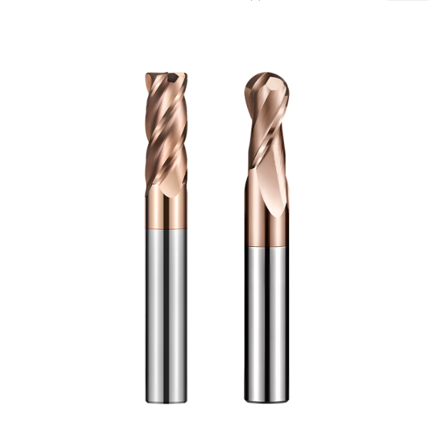
Why do we recommend replacing sharp-cornered flat end mills with corner radius end mills for milling hardened steel molds?
Many mold shops still rely on standard square end mills unless a print explicitly calls for an internal radius. When cutting hardened tool steels, this habit carries a steep hidden cost. The fragile 90° corner takes the brunt of alternating shock loads during cavity profiling. That sharp point quickly develops micro-cracks, leading to sudden edge loss and inconsistent cycle times.
Swapping square tooling for a corner radius end mill is a proven process upgrade. You may need a tiny secondary pencil-milling pass for rare dead-sharp corners, but the payoff is substantial. You get a massive boost in tool life, lower spindle vibration, and a stable window for lights-out machining. The floor stability easily justifies that quick extra cleanup step.
Insights from Mold Tool Chipping: Stress Concentration at Sharp Tips vs. Force Dispersion in Corner-Radius End Mills
Under a shop stereomicroscope, broken flat tools almost always show damage right at the sharp outer corner. Without a radius, heavy cutting loads concentrate on a single microscopic point. Thermal spikes and mechanical shear create an instant stress notch. Once that tiny fracture forms, hard material impacts drive it across the carbide grains, breaking the entire tooth.
A ground corner radius fundamentally transforms how a corner radius end mill for hardened steel absorbs cut resistance. The smooth radius directs cutting forces along normal vectors toward the rigid tool core. It also increases the carbide mass at the edge to dissipate heat faster. Instead of hammering the steel, the tool peels chips smoothly and easily absorbs rapid direction changes in tight corners.
Clearing Bottom Corners in High-Hardness Machining (HRC 50–65): Using Corner Radii to Drastically Reduce Manual Mold Polishing Time
Bench polishing remains one of the slowest and most expensive steps in mold making. Many machinists assume a flat end mill produces the flattest pocket floor. In reality, slight tool runout or machine flutter causes sharp corners to plow deep, uneven witness marks across hard surfaces. Hand-stoning those gouges out of HRC 50–65 steel takes hours and risks rounding off critical edges.
We resolve this by semi-finishing and finishing floors with a carbide corner radius end mill. The slight radius transition leaves consistent, microscopic cusps that are predictable and easy to blend. You can widen your stepover to slash cycle times while delivering a flatter surface to the bench. In most cases, a brief polish brings the cavity straight to final spec.
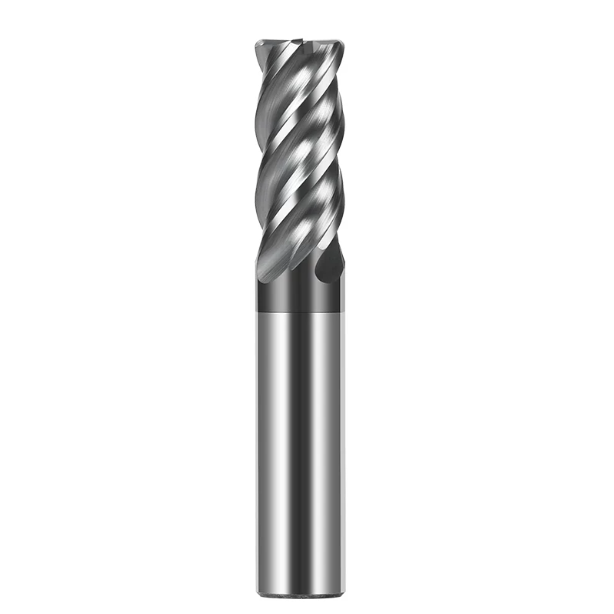
Matching Substrate and Coating for Solid Carbide Corner Radius End Mills: Our Empirical Data from Deep-Cavity Machining
Deep cavities with 4xD or greater overhangs often trigger sudden tool breakage, even with high-hardness cutters. Machinists frequently assume ultra-hard carbide rods and thick coatings will power through. But long overhangs magnify cutting deflection and chip friction inside narrow ribs. If the core substrate lacks dynamic toughness, the best edge prep will still crack under load.
A high-performance solid carbide corner radius end mill requires strict balance between core toughness and surface barrier properties. The substrate must flex slightly to absorb impact while keeping the tool spinning true. Meanwhile, the outer coating must block cutting heat from sinking into the carbide matrix. Balancing these thermal and physical properties ensures steady, long-lasting cuts during dry or MQL operations.
Rigidity Considerations for Selecting Ultra-Fine Grain Carbide Corner Radius End Mills for Heat-Treated Mold Steels (SKD11 / D2 / H13)
Hardened cold-work and hot-work steels contain dense, abrasive chromium and molybdenum carbide inclusions. Passing a cutting edge through these hard phases feels like a microscopic hammer strike. If the carbide substrate has coarse grains or too little cobalt binder, the corner will micro-fracture along its grain boundaries, destroying the radius geometry within minutes.
For deep cavities, we rely on sub-micron carbide grades with grain sizes between 0.2 and 0.5 microns to make our carbide corner radius end mills. This tight grain structure significantly boosts transverse rupture strength (TRS). The cutter resists bending forces during interrupted cuts and keeps the depth of cut consistent. Sacrificing a fraction of ambient hardness for superior fracture toughness reliably protects valuable inserts.
Handling High Cutting-Zone Temperatures Exceeding 1000°C: Coating Spalling Resistance on Carbide Corner Radius End Mills
Trapped chips cannot escape easily during high-speed milling in deep cavities, and friction quickly drives cutting zone temperatures above 1000°C. Standard single-layer TiAlN coatings oxidize rapidly under these conditions. Worse, thermal expansion mismatches cause the film to peel right off the carbide substrate. Once the coating fails, hot chips quickly wash out the exposed corner through crater wear.
To stop this breakdown, we apply nano-multilayer Al-Cr-Ti or Al-Si coatings to our carbide corner radius end mills suppliers catalog. High cutting heat forces this coating to form a slick, self-healing aluminum oxide layer on the wear flank. The nano-layers also arrest micro-cracks before they reach the substrate, keeping the protective film anchored to the radiused edge throughout long dry runs.
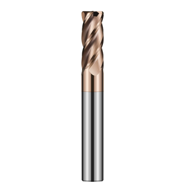
2-Flute vs 4-Flute Corner Radius End Mills: Roles in Deep-Cavity Mold Roughing and Finishing
Deep mold cavities with steep walls constantly force programmers to choose between 2-flute and 4-flute tools. Operators often grab a 4-flute tool to rough out deep pockets simply for convenience. Chips quickly pack into the narrow flutes, work-harden, and snap the tool tip. Conversely, using a 2-flute tool on tall sidewalls causes heavy deflection, leaving wavy chatter marks behind.
We draw a hard line between chip clearance volume and lateral core rigidity. Roughing deep slots requires large gullets to evacuate heavy chips and stop re-cutting. When shifting to finishing passes, cuts drop to the micron range and deflection becomes the main enemy. Alternating between a 2 flutes end mill corner radius and a 4-flute tool delivers speed without sacrificing tolerance.
Chip Evacuation and Clearance Strategies for 2-Flute Corner Radius End Mills in Deep Closed Cavities and Plunge Milling
When helical ramping or plunge milling in deep cavities, chips must clear the cut zone within milliseconds. Without adequate flute volume, red-hot chips weld together at the cavity bottom and pack the tool flutes. When roughing large automotive dies, we frequently step in to stop operators from running high-flute cutters in deep blind pockets.
Choosing a dedicated 2 flutes end mill corner radius gives chips a clean, wide escape path during steep ramps. The radiused corners take the brunt of vertical plunge forces without chipping. Meanwhile, twin wide flutes let high-pressure air blast tightly coiled chips out of the pocket. That extra chip clearance provides reliable security against tool breakage during unattended roughing.
Rigidity Advantages and Chatter Suppression Techniques for 4-Flute Corner-Radius End Mills in Mold Core Sidewall Finishing
Chip clearance takes a back seat once you reach the sidewall finishing stage. Here, web rigidity and resonance control dictate your final part quality. The smaller core of a 2-flute cutter flexes under steady side loads, especially with long overhangs. That deflection triggers loud spindle chatter, gouging the hardened wall and leaving steps at corner blend zones.
To cut clean sidewalls, switch to a rigid 4 flutes corner radius end mill. The beefier cross-section limits tool deflection under cutting pressure. Pairing variable helix angles with unequal flute indexing breaks up harmonic resonance before chatter can start. The corner radius also steers cutting forces up the spindle axis, producing smooth, gouge-free walls that skip hand polishing.
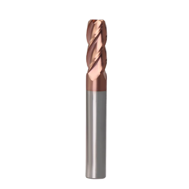
Conquering Extreme Hardness: Practical Cutting Parameters and Toolpath Strategies for HRC65 Corner Radius End Mills
Cutting hardened cold-work steels up to HRC65 completely alters chip formation mechanics. At this hardness, the steel loses its plastic deformation capacity and resists shear with intense force. Using feed rates or toolpaths meant for pre-hardened steels burns the edge in minutes. You cannot brute-force your way through powder metallurgy steels.
Success with an hrc65 corner radius end mill comes down to controlling radial cutter engagement and dynamic machine dampening. Do not chase high surface footage here. Instead, focus on smooth, roll-in toolpath entries and consistent material removal rates. Maintaining a balanced radial load allows the corner radius to peel chips away smoothly without shock-loading the carbide.
Why Must HRC65 Corner Radius End Mills Employ “Low Ap / High Feed” Dynamic Milling Strategies?
Machinists stepping into hard milling often rely on deep axial cuts paired with crawl-pace feed rates. In HRC65 steel, heavy step-downs exert massive bending loads on the tool neck. The corner radius must absorb violent shear forces, which quickly exceed the carbide’s yield strength and trigger sudden edge failure.
We always implement a “Low Ap, High Feed” strategy for extreme hardness. Running an hrc65 corner radius end mill with axial step-downs at 2% to 5% of tool diameter directs cutting forces straight up the spindle. Machine tools handle axial loads far better than side deflection. This reduces chatter and lets the radiused edge cut reliably at elevated feed rates.
Air Blast or Dry Milling? Strategies to Prevent Thermal Cracking with HRC65 Corner Radius End Mills in Ultra-Hard Machining
Operators often flood the tool zone with coolant to battle the intense heat of hard milling. We immediately shut off wet coolant lines on these setups. Carbide handles heat well, but it cannot survive rapid thermal cycling. Quenching a 1,000°C cutting zone with cold liquid cracks the corner radius along its micro-grain boundaries in seconds.
Instead, run a corner radius end mill for hardened steel completely dry using a cold-air blast or high-pressure MQL. Continuous air clears glowing chips instantly and maintains steady thermal equilibrium at the edge. Stable cutting temperatures allow advanced nano-composite coatings to build slick aluminum-oxide barriers that actively fight off heat-induced edge spalling.
The Cost of Ignoring the Chip Thinning Effect: Correcting Feed Rate Calculation Errors in Customer Workshops
We often catch skilled CAM programmers calculating feeds with standard catalog formulas, ignoring effective chip thickness. When axial cut depths drop well below the corner radius, the actual chip cut by the round edge is razor-thin. Running unadjusted feed rates causes the edge to rub and burnish instead of cutting clean metal.
Rubbing creates severe work-hardening on hardened die steel, generating enough friction to strip coatings in seconds. When taking light cleanup passes with a carbide corner radius end mill, you must calculate chip-thinning compensation. Bumping the programmed table feed forces the cutting edge to bite under the glaze layer, shearing off clean chips and protecting tool life.
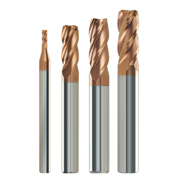
Why do mold shops frequently encounter premature edge chipping with corner radius end mills for hardened steel? Our frontline troubleshooting checklist
Step into a mold shop and listen for irregular clicking from the spindle. If operators swap cutters every two hours, the corner radius chipped prematurely. Most shops instinctively blame inconsistent heat treatment or defective carbide batches. But in hardened steel, any microscopic vibration instantly turns into destructive shear stress at the tool tip.
We treat the spindle, holder, toolpath, and cutter as a closed-loop rigid system. Premature failure of a corner radius end mill for hardened steel usually stems from compounded errors like clamping runout or corner deceleration spikes. Auditing setup data directly at the machine spindle uncovers the true root cause and restores reliable cutting.
The devastating impact of tool holder radial runout (TIR) exceeding 0.005mm on the lifespan of corner radius end mills for hardened steel
When inspecting chipped tools on-site, we reach for a 0.002mm dial test indicator before touching feed overrides. Many shops consider 0.01mm or 0.02mm runout acceptable for daily milling. In HRC 55+ steel, that error is lethal. Excessive runout degrades multi-flute milling into single-tooth loading, overloading one edge until it fractures.
Switching from collet chucks to shrink-fit or hydraulic holders drops runout below 0.003mm, instantly doubling tool life. Uniform runout ensures every flute takes an identical chip load across the hardened surface, preventing cyclical fatigue cracks. Investing in low-TIR toolholders protects your corner radius end mill for hardened steel far better than dialing back feeds.
Tool marks and overcutting at the corner radius transition: Optimizing CAM path tolerances on the shop floor
Machinists often notice distinct witness marks or slight gouging where the floor arc meets the vertical wall. These flaws rarely stem from worn machine guideways. Instead, coarse CAM calculation tolerances cause micro-pauses during rapid directional shifts. When the tool dwells against hardened stock for milliseconds, the corner radius bites too deep.
We resolve this by setting CAM calculation tolerances (Intol/Outtol) below 0.002mm and enabling arc-fitting filters. A rigid 4 flutes corner radius end mill can then sweep smoothly through transition vectors without stuttering or dwelling. Tight vector spacing maintains constant chip load and prevents sudden engagement spikes that chip the radiused edge.
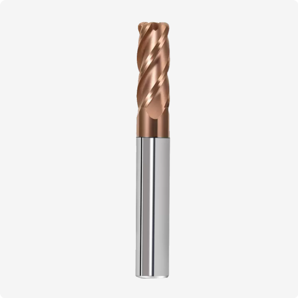
Procurement Standards from the Manufacturer’s Perspective: How European and American Precision Mold Shops Evaluate Corner Radius End Mill Suppliers
Many shops invest heavily in 5-axis machines, CAM seats, and shrink-fit toolholders, only to buy bargain cutters for mass production. In hardened mold steel, tooling is an engineered component, not a commodity. Buyers often inspect basic length and shank diameter while missing the micro-geometry and internal stresses that govern real-world tool life.
Top-tier mold manufacturers audit how prospective corner radius end mills suppliers control tolerances at the grinding spindle. Reliable vendors document carbide grain distribution, wheel dressing intervals, and PVD coating adhesion. Controlling micro-inch variations at the factory protects your machines from erratic tool failures and costly scrapped inserts.
5-Axis Tool Grinding and Inspection Tolerances: The Baseline for Profile Accuracy Control by High-Quality Corner Radius End Mill Suppliers
Operators frequently report that replacing a worn tool with a new one creates a 0.01mm step on the cavity wall. This mismatch occurs when grinding wheels wear unevenly, creating a tangent discontinuity where the radius blends into the side flutes. Without closed-loop optical compensation, the theoretical arc degrades into a faceted, polygonal edge.
Premium corner radius end mills suppliers link 5-axis tool grinders to optical comparators, holding radius profile tolerances within ±0.003mm. If your bench team spends entire shifts hand-stoning witness marks out of cavity corners, inspect the tool profile under 50x magnification. A sharp transition line on the cutter will always replicate as an unwanted mark on your mold.
Eliminating Batch-to-Batch Tolerance Fluctuations: Key Quality Metrics We Audit with Leading Corner Radius End Mill Suppliers
Few things disrupt a production schedule faster than a tool shipment that runs for twenty minutes after the previous lot ran for four hours. When auditing manufacturing partners, our primary metric is batch-to-batch dispersion. We evaluate edge-honing consistency across every flute and map surface residual stress profiles after PVD coating.
If your shop faces unexplained micro-chipping in HRC 50+ mold cores, verify your holder runout and programmed chip thinning. If you machine complex deep-cavity dies, tight corner tolerances, or powder metallurgy alloys, we are glad to review your prints and setups. Sharing actual speeds, feeds, and material grades helps us solve tough machining problems together.