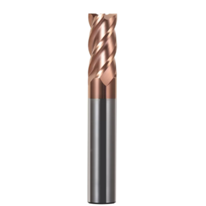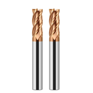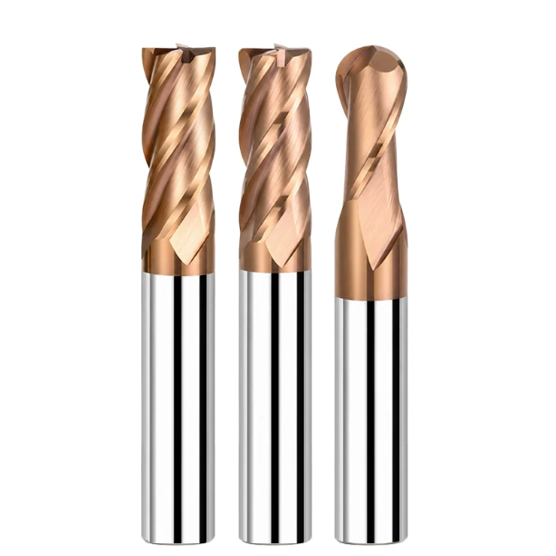
Three months ago, an Ohio precision mold shop sent us an emergency-stop video. A 6-flute ball-nose end mill snapped clean in half after four minutes inside a 5-axis machine. The part was 1.2379 (D2) cold-work tool steel, fully hardened to 64 HRC. The operator immediately blamed a brittle carbide substrate and aggressive feeds.
Our remote check of spindle load curves and field inspection data told a different story. Residual tool holder runout was sitting at 7 microns, climb-milling entry lacked an arc deceleration move, and the coating failed against the 900°C friction spike in dry cutting. Over sixteen years supporting US and European tooling facilities, we have tackled this exact failure pattern dozens of times.
When stock hits 60 HRC, conventional machining habits backfire completely. Operators often back off spindle speeds to “protect” the cutting edge, which accelerates catastrophic failure. Successfully running an HRC65 end mill is never just about the nominal rating stamped on the packaging. Milling hardened steel is a micro-scale battle against cyclic mechanical shock and extreme friction:
- Substrate & Edge Prep: A solid carbide end mill requires ultra-fine grain matrix tuning and high transverse rupture strength. A negative rake sets up a compressive stress field, while edge honing dictates whether the tool shears cleanly or chips against hard matrix carbides.
- Core & Flute Layout: For any hardened steel end mill, core diameter and unequal helix spacing govern structural rigidity during long-overhang cuts.
- Thermal Barrier: Advanced HRC65 end mill coating layers must form a dense protective oxide skin under extreme heat. Without this barrier, the cobalt binder softens in seconds.
Once runout is clamped inside 3 microns using shrink-fit holders, toolpath dynamics decide the outcome. Why do standard catalog cutting speeds still cause unexpected micro-chipping in deep cavity corners?
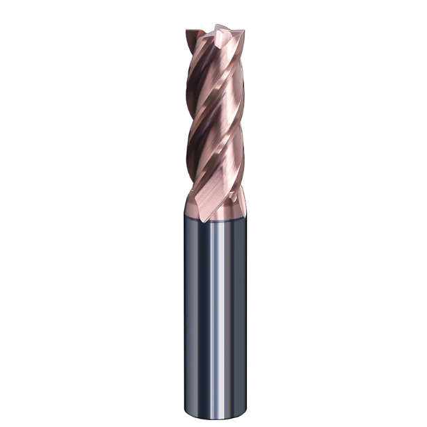
Core Logic of Tool Selection: Why Do Conventional Carbide Tools Chip Instantly on HRC65 Steel?
Run a general-purpose end mill on 65 HRC tool steel, and you will hear a sharp snap almost immediately. Many operators instinctively drop the feed rate or slow the spindle down. That change usually causes the replacement tool to chip even faster. High-speed video shows that ultra-hard materials produce an extremely narrow plastic deformation zone. A standard positive rake face cannot shear this material cleanly; it plows and crushes the steel until the cutting edge fractures under tension.
This extreme contact removes the elastic buffer that general-purpose tools rely on. Under massive contact pressures, the cobalt binder matrix softens and loses its grip on the tungsten carbide grains. When selecting a high-performance HRC65 end mill, our first task is dispelling a common myth: the goal is not a razor-sharp edge that glides through steel. Instead, you need a rigid micro-profile that redirects cutting forces into pure compression before the tool tip shatters.
Empirical Analysis of Substrate Grain Size: Balancing Impact Resistance and Hardness in Carbide End Mill Selection
Machinists often assume that finer grain size or higher hardness is always better. Tensile tests and milling trials on 0.2-micron versus 0.5-micron grades reveal a more complex trade-off. Sub-micron grades below 0.2 microns reach extreme hardness above 93 HRA, but their fracture toughness drops sharply. A single hard spot from uneven heat treatment can shatter the tool like glass.
During our field-testing for carbide end mill selection, we favor an 8% cobalt matrix paired with a 0.4 to 0.6-micron sub-micron grain structure. This composition sacrifices less than 0.5 HRA in raw hardness compared to ultra-fine grades. In exchange, it maintains a transverse rupture strength above 4000 MPa. That extra toughness prevents tooth breakage during interrupted cuts in Caldie or hardened D2.
From Crushing to Micro-chipping: Failure Mechanisms of Hardened Steel End Mills in Extreme Cutting (HRC 60–68)
Under a 200x toolmaker’s microscope, normal wear and catastrophic failure look completely different. During dry milling tests with a dedicated hardened steel end mill, the failure process starts when the nanocoating wears through. The exposed cobalt binder softens near 800°C. The rake face then suffers micro-scale plastic collapse, destroying the mechanical support behind the hone.
Once plastic collapse alters the edge profile, cutting friction spikes sharply. Micro-cracks spread along the carbide grain boundaries and turn into visible edge chipping. Operators often blame high feed rates, but our data shows that underfeeding is the primary culprit. When the chip thickness drops below the edge hone radius, the tool rubs and work-hardens the surface instead of cutting.
Geometry Determines Lifespan: HRC65 End Mill Geometry and Edge Strengthening Parameters
Many engineers rely entirely on catalog hardness ratings and coating trade names. If the micro-geometry is flawed, the best carbide substrate will fail within two passes. During an audit for a Swiss medical mold shop cutting 63 HRC powder-metallurgy steel, identical tools showed a threefold variation in tool life. The difference came down to flute grind quality and micro-honing profiles on the cutting edge.
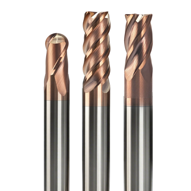
Tools built for hardened materials look noticeably blunt under inspection. Optimizing HRC65 end mill geometry requires balancing wedge strength against cutting resistance. We replace standard positive rakes with zero or negative rake angles and thicken the flute floor with a generous blend radius. This directs cutting forces into the solid core of the tool body rather than leaving an unsupported tip to take the hit.
Negative Rake & T-Land: Core Design Features to Prevent Chipping in High-Hardness Milling Tools
Standard finishing cutters use positive rakes for easy shearing. On hardened mold steel, that thin wedge fractures on the first pass. Our tool grinding data confirms that radial rake angles must stay within -8° to -12°. While a negative rake increases radial tool pressure, it directs the primary cutting vector straight into the tool body. This sets up a hydrostatic stress state that suppresses tensile cracks between carbide grains.
To maximize tool life on a high hardness milling tool, combine that negative rake with an engineered T-land and controlled edge hone. A razor-sharp edge chips within the first two meters of cutting. Adding a 0.03 to 0.05 mm wide chamfer at -15°, paired with a 10 to 15-micron hone, reinforces the edge against shock. The friction also generates local shear-zone heat that softens the steel for stable cutting.
Variable Core & Unequal Helix: Empirical Ratios for Eliminating Self-Excited Chatter
Chatter is far more destructive to solid carbide tools than gradual flank wear. While troubleshooting a stamping die in Detroit, we found that taking cuts deeper than 0.1 mm caused loud chatter and surface washboard marks. A tool inspection revealed the issue: deep flutes left the core diameter at only 58% of the tool’s outer diameter. High cutting resistance forced the tool to deflect and chatter.
For hardened steel finishing, we raise the core diameter to 65% or 72% of the outer diameter and use a reinforced back taper. To break up harmonic resonance, we combine variable helix angles (such as 38°/41°) with unequal flute spacing (such as 88°/92°). This geometry limits chip clearance, but light radial cuts produce very fine chips. The resulting tool rigidity stabilizes cutting and stops premature chipping.

Balancing Flute Count and Rigidity: Selecting the Right Configuration for HRC65 End Mills (4 Flutes, 6 Flutes, or More?)
In many shops, machinists stick to 4-flute end mills for all hard metals. Others switch directly to 6-flute or 8-flute cutters for high-speed finishing. Every tool body has a fixed cross-sectional area. Adding a flute forces you to narrow the chip gullet or thin the tool core. You cannot add cutting edges without trading away chip clearance.
Hardened metal finishing relies on light radial engagement (ae) and high table feed rates (Vf). The resulting chips look like dust, making gullet capacity less critical. When choosing an HRC65 end mill flute configuration, the real goal is balancing core stiffness against instantaneous chip evacuation. More flutes spread impact loads across multiple teeth while keeping metal removal rates high.
4-Flute vs 6-Flute End Mills for Hardened Steel: Overhang Limits in Side Milling and Profile Milling
The number of flutes sets the true ceiling for feed rates during shallow profiling and contouring. During benchmark tests at a Michigan auto mold plant, we compared tools held within a short $3D$ overhang. At 12,000 RPM, a 6-flute tool allowed a 50% higher table feed than a standard 4-flute cutter. The tighter tooth engagement stabilized cutting forces and produced sidewall finishes comparable to grinding.
Extending the tool overhang beyond 4D changes the cutting dynamics completely. A 6-flute cutter creates continuous lateral friction along long shanks, building up torsional stress. Uneven stock then triggers high-frequency chatter. When running a 4-flute vs 6-flute end mill for hardened steel at long overhangs, the 4-flute design wins. Its wider tooth spacing allows the tool to flex and recover cleanly without chipping.
Addressing Deep Mold Cavity Slots and Tight Corners: Balancing Chip Evacuation and Cutting Width for HRC62 Steel
Deep slots and tight internal radii present the greatest risk of tool breakage in mold cavities. While troubleshooting 62 HRC wear plates, we found tools consistently snapping inside internal corners. Toolpath analysis showed the cutter engagement angle spiking from 30° to 180° in sharp turns. This surge packs flutes with chips within a half revolution, causing heat buildup and catastrophic tip failure.
For narrow slots and corners, we follow a simple rule: fewer flutes and larger chip gullets. Even for finishing, an end mill for HRC62 steel in a deep corner should use a 4-flute geometry with neck relief. Program an arc blend or trochoidal entry, keeping radial stepover between 2% and 5% of tool diameter. High-pressure air blasts can then flush chips freely and prevent tooth crowding.
Real-World Coating Temperature Resistance and Adhesion: HRC65 End Mill Coatings and High-Temperature Dry Cutting Solutions
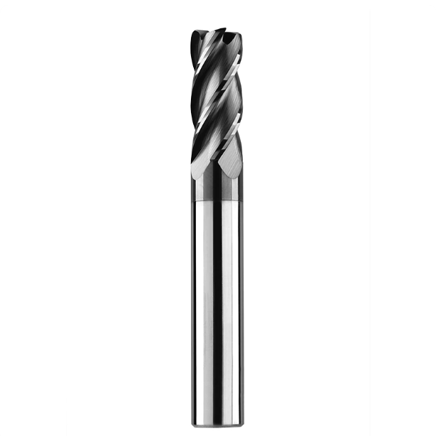
When cutting edges wear out quickly, operators often blame coating hardness and look for ratings above 3800 HV. In our testing on 65 HRC workpieces, contact zone friction routinely drives local temperatures past 900°C. Extreme thermal environments demand more than raw room-temperature hardness. The coating’s oxidation barrier, thermal stability, and adhesion to the carbide substrate determine whether the tool survives.
If a coating flakes under early thermal shock, the bare substrate suffers rapid diffusion wear. In developing our HRC65 end mill coating strategy, we look past standard catalog Vickers ratings. We focus on how readily the film forms a protective oxide layer under sustained heat. An effective coating acts as a thermal shield, allowing cutting heat to soften the shear zone while keeping the core carbide cool.
Performance Analysis of AlTiSiN/TiSiN Nanocomposite Coatings: Spalling Resistance on Solid Carbide End Mills for HRC65 Hardened Steel
Standard AlTiN coatings break down and oxidize rapidly at temperatures above 800°C. In Sweden, we tested specialized coatings on 64 HRC hot-work die steels. The nanocomposite TiSiN coating outperformed conventional single-layer alternatives. Silicon additions form an amorphous silicon nitride (Si3N4) matrix around the grain boundaries. This barrier blocks grain boundary sliding and raises the oxidation threshold beyond 1100°C.
Interfacial adhesion is just as critical during interrupted side milling. On an HRC65 solid carbide end mill, nanocomposite TiSiN structures resist micro-crack propagation under heavy cyclic shock. In scratch adhesion tests, these films consistently top 80 N. This bond strength prevents edge flaking and delamination. A durable self-healing oxide layer forms on the rake face, keeping flank wear predictable and slow.
Cold Air or Minimum Quantity Lubrication (MQL)? Chip-Breaking and Cooling Guidelines to Prevent Thermal Cracking in High-Speed Milling of Hardened Steel
Flooding the cutting zone with liquid coolant on hard steel is a guaranteed way to break carbide. The cutting edge heats up to roughly 1000°C in the cut, then gets quenched the moment it exits. This extreme thermal cycling creates comb-like micro-cracks perpendicular to the edge within minutes. These thermal cracks quickly cause structural edge flaking and broken teeth.
For high-speed hard milling, use dry cutting with a clean, high-pressure air blast instead. The goal is not to cool the tool tip, as local heat helps soften the shear zone. High-pressure air clears hot, abrasive chips instantly so the flutes never re-cut them. In deep cavities prone to heat buildup, add an MQL system running 10 to 20 ml/hr of vegetable oil to reduce friction without causing thermal shock.

Workshop-Tested Parameters: Cutting Fundamentals and Toolpath Strategies for End Mills Machining Hardened Steel
When cutting metals above 60 HRC, many operators drop surface speed (Vc) to protect the tool. This often backfires. Low cutting speeds prevent the shear zone from heating up enough to soften the material. Spindle load spikes, causing rapid abrasive wear from direct friction against the hard matrix. The relationship between cutting speed, axial depth (ap), and radial width (ae) requires a different strategy on hard steels.
When setting parameters for an end mill for hardened steel, our baseline rule is simple: limit radial width, increase axial depth, and raise surface speed. On 62–65 HRC steels, we run surface speeds between 100 and 160 m/min. We keep radial engagement tight, typically between 2% and 8% of the cutter diameter. This short contact arc lets chips carry cutting heat away before it can soak into the tool tip.
Trochoidal Milling and High-Speed Finishing: Dynamic Compensation Algorithms for ae and fz
Programmers running shallow side cuts often pull feed-per-tooth (fz) values straight from tooling catalogs. This usually leads to poor cycle times and tool rubbing. When radial width drops below 10% of tool diameter, the true chip thickness ($hm$) shrinks far below the programmed feed per tooth. Without chip thinning compensation, actual chip thickness falls below the edge hone radius, causing the tool to rub and work-harden the cut.
For trochoidal milling or light radial finishing, we apply compensation formulas to bump feed rates by 1.5 to 2.5 times. This ensures the edge bites cleanly into the shear zone. On toolpath corners, replace sharp directional changes with smooth trochoidal loops or arc entries. Smoothing out the engagement angle prevents force spikes far better than adjusting the feed override switch on the machine pendant.
Machining Strategies for Stress-Discontinuity Zones in Hardened Mold Steels (D2, Cr12MoV, NAK80)
Quenched and tempered tool steels rarely have uniform internal stress. At an injection mold shop in Italy, we troubleshot roughing deformation on large 62 HRC D2 blocks. Cooling gradients near the core and bolt holes caused local hardness to swing by 3 to 4 HRC, leaving high residual tensile stress. Driving a cutter through these zones at a fixed feed rate turns minor tool deflection into sudden impact shock.
On high-carbon, high-chromium steels, we replace heavy single-pass cuts with constant-Z slicing and light stepovers. Near deep pockets, ribs, or heat-treated edges, we program a 20% to 30% feed reduction zone. We also run a semi-finishing pass to clear surface variations left by stress-relief movement. Smoothing stock variations down to the micron level keeps cutting forces stable and within the tool’s elastic limits.
Frequent Customer Complaints and On-Site Troubleshooting in Western Workshops
About 70% of reported “tool quality issues” on hard steel trace back to setup errors or thermal shock. Our earlier sections covered core toughness, negative rakes with micro-hones, thermal barrier coatings, and light radial toolpaths. Shop environments add unpredictable variables, like guide-way backlash or dirty collet bores. A single setup issue can ruin an otherwise solid cutting process.
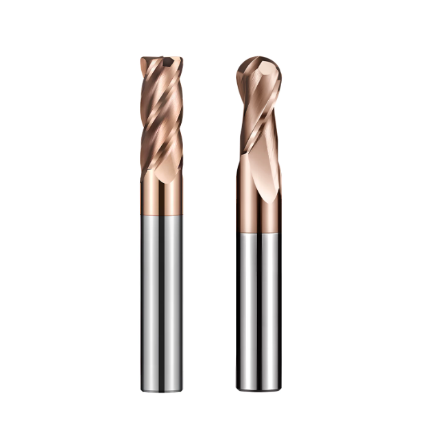
If you are using a hardened steel end mill that fails early, do not just turn down the feed rate or scrap the batch. Stop the spindle and inspect the failure mode. Look at the cutting edge under magnification to see whether it chipped from impact or cracked from heat. Checking the total assembly runout in the spindle face usually reveals the root cause within minutes.
Early Tip Wear or Thermal Cracking? Rapid On-Site Criteria for Determining End-of-Tool-Life
Dim shop lighting can make flank wear look like simple abrasive breakdown. We always inspect worn edges with a 50x pocket microscope. A smooth, even wear land under 0.1 mm wide with a faint metallic shine indicates normal flank wear. Fine comb-like cracks perpendicular to the cutting edge or shell-shaped craters point to thermal fatigue cracking from cyclic heat shock.
If you see thermal cracking on steel harder than 60 HRC, check your air blast pressure first; it should stay above 0.6 MPa. Cut off all liquid coolant, switch to dry air to clear chips, and drop cutting speed by 10% to 15% to stabilize temperatures. If the microscope shows clean flank wear spreading too quickly without micro-cracks, reduce radial depth and raise chip load to keep heat moving into the chips.
Toolholder Runout and Spindle Dynamic Balance: How to Prevent Radial Runout Exceeding 3 μm from Ruining an Entire Batch of Solid Carbide End Mills
In hard milling, radial runout directly dictates tool fatigue life. When radial depth is set to a delicate 0.05 to 0.1 mm, a 5-micron runout means one tooth takes nearly double the cutting load. The opposite tooth barely touches the cut. This cyclic shock quickly fractures the overloaded tooth, triggering a chain reaction that breaks the remaining flutes.
If you run high-hardness work in standard ER collets, check the total runout with an indicator $1.5D$ down the shank. If the needle swings past 3 microns, tool life will suffer regardless of carbide grade. For hardened steels, mount every solid carbide end mill in a shrink-fit or hydraulic chuck balanced to G2.5 above 15,000 RPM. Holding runout under 3 microns is essential for consistent tool life.