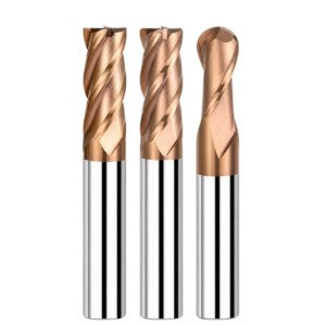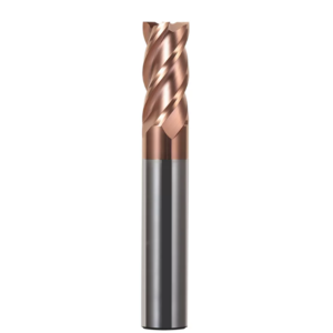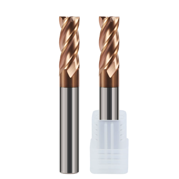
Last month, an injection mold manufacturer in Ohio sent an urgent scrap report directly to our technical inbox. They were finish-milling a slide insert made of AISI D2 tool steel (quenched to 62 HRC) on a high-speed 5-axis machine. Just as the tool reached the right-angle corner-clearing pass on the third part, the spindle shrieked. The 90° corner of their solid carbide cutter chipped catastrophically, scoring the cavity wall by 0.04 mm and scrapping a $3,200 component.
This scenario is common across our technical support records. Many machinists facing 55–65 HRC steels instinctively reduce feed rates or flood the cut with water-soluble coolant. In hard milling, however, low speeds increase frictional rubbing, while liquid coolant induces violent thermal shock that fractures carbide. At this hardness, metal removal shifts from plastic shearing to localized compressive deformation, meaning conventional tooling logic fails immediately.
Under extreme contact pressure, a standard square end mill has an Achilles’ heel: its unsupported 90° corner. Without edge-prep optimization, optimized substrate grain sizes, and high-heat coatings, standard tools burn out within minutes. Reliable machining requires balanced core rigidity, vibration-dampening flutes, micro-trochoidal paths, and dedicated hrc65 carbide square end mills. Does your shop battle this cycle where end mill corners fail before completing even two parts?
Real-World Pain Points in Hardened Steel Machining: Why Do Standard Square End Mills Frequently Fail When Cutting 55–65 HRC Materials?
When workpiece hardness climbs into the 55–65 HRC range, traditional cutting mechanics no longer apply. A general-purpose square end mill that performs smoothly in medium-carbon steel meets extreme radial resistance here. As spindle loads spike, cutting forces create immense unit compressive stress on the tip. Without dedicated high-hardness geometries, micro-fractures propagate through the carbide matrix within seconds.
Operators often try to salvage tool life by halving cutting speeds and lowering feed rates. This intuition backfires. Sub-optimal surface speeds fail to evacuate friction-generated heat, forcing the cutting edge to rub against abrasive carbide precipitates. This cycle accelerates mechanical fatigue, proving that machining hardened steel requires high red hardness, proven micro-geometry, and unyielding edge stability.
The Disaster of Micro-Chipping at 90° Tool Tips: Analyzing the Dual Mechanisms of Thermal Stress and Mechanical Impact in D2 and DC53 Punch Machining
While troubleshooting a stamping tooling project, we audited a line producing punches from D2 and DC53 cold-work die steels (60 HRC). When using an off-the-shelf square end mill for hardened steel to clear sharp internal corners, the tips failed within two cycles. Microscopic inspection showed classic thermo-mechanical spalling: failure started at the outermost microns of the 90° corner and flaked toward the flank.
Sharp corners possess negligible mass to dissipate thermal energy. Contact-zone temperatures rapidly exceed 900°C, while the tool body stays cool, generating a steep thermal gradient and cyclical stress. Paired with hard carbides in DC53, every tooth impact acts like a micro-hammer. Without an engineered negative chamfer, these combined stresses destroy sharp corners.
Zero Margin for Error in Tool Selection: Why Standard End Mills for Pre-Hardened Steel (HRC 30–40) Fail on Quenched Parts?
Shops often assume an end mill meant for P20 or 718H (HRC 30–40) can handle 58 HRC simply because it has a premium coating. We have seen this assumption ruin many valuable workpieces. Pre-hardened steels allow plastic shearing, demanding deep flutes and positive rake angles for chip evacuation. Those same geometries prove fatal in fully hardened tool steel.
High-hardness machining demands the opposite geometric approach. Deep chip gullets compromise the core diameter, causing excessive deflection and cutter snap under load. Positive rake edges lack back-support and chip instantly against hard matrices. A 15% programming error in 35 HRC steel merely accelerates wear; in 62 HRC steel, inadequate edge support causes immediate, catastrophic failure.
Tool Deflection and Workpiece Wall Taper: How We Resolved Dimensional Deviation in Deep-Cavity Square-Shoulder Milling for a German Automotive Mold Manufacturer
A moldmaker in Stuttgart asked us to resolve a taper defect in deep-cavity inserts (62 HRC) milled at a 4×D overhang. Coordinate measuring machine (CMM) reports showed a 0.035 mm deviation along the cavity floor, along with heavy witness marks at the base. Switching between standard carbide square end mills from major catalog brands failed to resolve the taper.
The root cause was microscopic deflection from radial cutting forces. Although solid carbide features high elastic modulus, the sheer resistance of 62 HRC steel flexed the 4×D setup out of tolerance. Rather than moving to a larger tool, we deployed a custom variable-helix design and dropped the radial stepover (Ae) to 0.04 mm using multi-pass profiling. This cut radial resistance and brought sidewall taper under 0.005 mm.
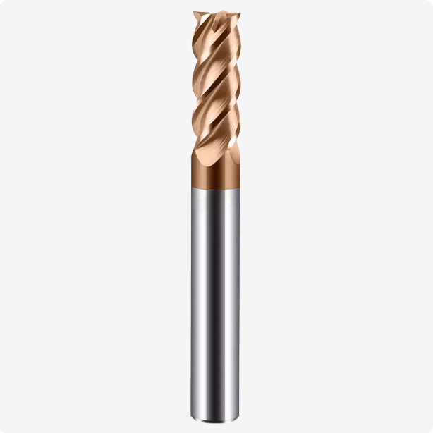
Tool Rigidity and Flute Configuration—Key Performance of 4-Flute Square End Mills in Hardened Steel Finish Milling
When milling 55–65 HRC stock, the cutter experiences constant, high-frequency bending forces. While two- or three-flute tools excel at roughing soft metals, a 4 flutes square end mill is the essential standard for finish-profiling hardened die steels. Four flutes provide the core mass required for structural rigidity while distributing the chip load evenly to prevent shock-load tooth breakage.
However, flute profiles must be carefully engineered for hard milling. Overly wide flutes weaken the cutter’s bending section modulus, leading to deflection and vibration. Conversely, excessively shallow flutes can trap fine, hot dust-like chips and cause edge welding. Balancing chip clearance with core mass directly determines shoulder squareness and tool life.
Practical Trade-offs Between Core Thickness and Chip Clearance: Setting Critical Core Thickness Values for Custom 4-Flute Square End Mills for Hardened Steel
When grinding a high-performance 4 flutes square end mill on our 5-axis CNC tool grinders, core diameter is our primary design parameter. General-purpose cutters typically use a web thickness of 50% to 55% of total tool diameter. For hard milling, this ratio is too flexible; we engineer our dedicated tools with a robust 62% to 68% core ratio, pushing up to 70% on long-reach finishing tools.
Machinists often ask: does a 70% web thickness cause chip packing? With high-hardness profiling, radial engagement stays under 5% of tool diameter (D), producing powdered dust rather than curled ribbons. Oversized flutes are unnecessary here; maximizing core web thickness reduces tool deflection exponentially, stabilizing the tool tip during tight side-wall cuts.
The Value of Edge Reinforcement via Negative Rake Angles: Empirical Data on Using Micro-Negative Chamfering (T-Land) to Prevent Micro-Chipping During Initial Engagement
Machinists often evaluate sharpness by running a fingernail along the cutting edge. However, an effective square end mill for hardened steel often feels relatively blunt to the touch. This profile is an intentional design choice: positive rake angles of 6° to 8° lack the mechanical backing needed for hard tool steels, leading to immediate edge collapse upon contact with primary carbides.
In testing on 62 HRC DC53, unmodified sharp edges showed continuous micro-chipping (0.02–0.04 mm) within three minutes of cut engagement, generating harsh spindle noise. By adding a 0.03 mm wide, -15° T-land chamfer combined with an 8–12 μm honed radius, the same tools achieved 45 minutes of stable cutting. Flank wear stayed predictable and linear, proving that controlled edge-prep forms a necessary shield against micro-chipping.
Variable Pitch and Variable Helix Design: How a North American Medical Tooling Manufacturer Eliminated Surface Chatter and Perpendicularity Defects Through Vibration Suppression
A medical fixture shop in California struggled with deep vertical chatter marks on 58 HRC hardened stainless components, where surface roughness remained stuck at Ra 0.8 μm. Their standard carbide square end mills with fixed 35° helix flutes generated loud harmonic resonance between 4,000 and 8,000 rpm, which pushed the workpiece sidewalls out of tolerance.
The issue was uniform tooth engagement: fixed helix flutes impact the workpiece at static time intervals, amplifying the setup’s natural resonant frequency. We resolved this by switching to an asymmetrical tool geometry featuring unequal index spacing and an alternating 38°/41° variable helix. This design disrupted harmonic feedback loops, eliminating chatter, reducing surface roughness below Ra 0.3 μm, and holding exact wall perpendicularity.
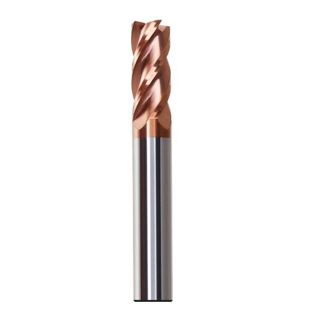
A Heavy-Duty Combination of Substrate and Coating: HRC65 Carbide Square End Mills for Extreme Hardness
Machinists tackling 55–65 HRC steels often assume rapid flank wear stems solely from coating breakdown or inadequate substrate hardness. In reality, hard milling is an unforgiving trade-off between abrasive resistance and fracture toughness. Our dedicated hrc65 carbide square end mills resolve this micro-structural conflict directly: brittle carbide substrates snap under impact, while standard coatings oxidize under intense dry-milling heat.
The substrate and coating must perform as an integrated load-bearing system. If the underlying tungsten rod lacks sufficient transverse rupture strength, high radial cutting forces trigger micro-plastic deformation. The surface film then collapses like ice over water. Hard milling demands a dense, sub-micron carbide core paired with an oxidation-resistant thermal barrier rated above 1,000°C.
Ultra-Fine Grain Size and Cobalt Ratio: The Optimal Alloy Substrate for Wear and Crack Resistance—Validated on the Shop Floor with D2 and Crucible CPM Steels
Machining high-vanadium powder metallurgy steels like D2 or Crucible CPM-10V quickly exposes the structural flaws of commodity carbide rods. Quenched to 62–64 HRC, these steels contain abrasive carbide precipitates that act like internal grinding wheels. In our shop audits, standard carbide square end mills rarely fail by gradual dulling; instead, hard inclusions initiate localized micro-cracks that propagate along grain boundaries.
Through extensive workshop cutting trials, we standardized on cemented carbide rods featuring a 0.2–0.4 μm ultra-fine grain size and 8%–10% cobalt content. Low cobalt yields high hardness but causes catastrophic chipping under side loads, while excess binder compromises flank wear resistance. This balance delivers 93–94 HRA hardness and over 3800 MPa rupture strength, arresting crack propagation during interrupted cuts.
Thermal Resistance Limits of Nanocomposite Si-Ti Coatings: Validating “Red Hardness” via 1100°C Oxidation Thresholds in Dry Cutting
Dry milling above 60 HRC produces extreme instantaneous cutting edge temperatures. Conventional AlTiN coatings begin lattice phase degradation near 800°C, where aluminum outward-diffusion triggers softening, oxidation, and rapid abrasive wear. For our high-performance square end mill for hardened steel tooling, we apply silicon-doped nanocomposite coatings, such as TiAlSiN and AlCrSiN.
Silicon forms an amorphous silicon dioxide (SiO2) surface layer that raises the oxidation resistance threshold past 1100°C. Nanocrystals embedded in this amorphous matrix reach 36–38 GPa hardness while functioning as a thermal barrier. This barrier deflects cut friction away from the core, preventing cobalt binder phase softening while holding critical dimensional tolerances.
Control of Cutting Edge Honing Parameters: Why an Excessively Sharp Tip Accelerates Tool Failure When Machining 62+ HRC Materials
Shop apprentices often assume that razor-sharp cutting edges reduce tool load and prolong cutter life. In hard milling, however, an unhoned razor edge is a primary failure point. A freshly ground square end mill without micro-edge preparation leaves an edge radius of just 2–4 μm. Under intense cutting pressures, this unsupported, razor-thin carbide ridge fractures instantly.
Our tests on 62 HRC tool steel confirm that unhoned corners develop erratic micro-chipping within seconds, accelerating wear across the flank face. By contrast, micro-honing the edge to a controlled 8–15 μm radius with a light corner negative chamfer shields the tip. While this increases initial radial load slightly, it prevents early chipping and ensures predictable tool life.

Shop-Floor Process and Parameter Execution: Toolpath Logic to Extend the Life of Square End Mills for Hardened Steel
When cutting tools fracture in hardened steels, operators typically blame the tool manufacturer. Yet reviewing the CNC code usually reveals aggressive or abrupt toolpath transitions as the true culprit. Because 55–65 HRC alloys possess minimal ductility, using a square end mill for hardened steel requires maintaining constant chip thickness and predictable cutting forces from entry to exit.
Traditional mold-making habits like straight plunging and abrupt 90° direction changes must be eliminated. Every sharp transition in the CAM path creates severe load spikes that shock the tool tip. Even on rigid 5-axis machining centers, toolpaths that fail to buffer high-hardness materials will break top-tier cutters due to instantaneous cross-sectional overload.
Strictly No Direct Plunging: Mandating 1°–2° Helical Ramping and Trochoidal Deceleration at Corners
While troubleshooting a die project in the UK, we watched an operator plunge a standard cutter straight down into a 60 HRC cavity floor along the Z-axis. This approach is fatal for any square end mill. Because surface speed drops to near zero at the tool center, direct plunging subjects the bottom teeth to brutal cold extrusion, causing immediate corner blowouts.
Our programming protocols require cavity entry via a 1° to 2° helical ramp or low-angle linear lead-in, converting axial thrust into manageable radial cutting forces. Additionally, when approaching internal corners, engagement angles spike from 90° to 180°. Programmers must apply trochoidal corner rounding and reduce feed rates by 30%–50% to prevent corner trapping.
Dynamic Milling (HEM) Parameter Window: Empirical Data Showing How Light Radial Engagement (Ae: 2%–8%) and Deep Axial Depth of Cut (Ap) Distribute Wear Evenly Across the Tool Tip
Traditional hard-milling routines rely on conservative depths of cut paired with heavy stepovers (small Ap, large Ae). This outdated strategy concentrates cut heat and abrasive forces directly on the fragile 90° corner. To maximize productivity with hrc65 carbide square end mills, workshops should pivot toward High-Efficiency Milling (HEM) toolpaths that utilize the entire flute length.
For 62 HRC tool steel, we run an axial depth (Ap) of 1.0–1.5× diameter and limit radial stepover (Ae) to 2%–8% of cutter diameter, increasing surface speeds to 100–140 m/min. Radial chip thinning allows higher feed rates, while spreading friction over the entire flute. This approach delivers significantly higher metal removal rates and prolongs tool life.
Practical Taboos Regarding Cooling Media: Why We Require Overseas Clients to Abandon Water-Soluble Emulsions in Favor of High-Pressure Air Cooling and Minimum Quantity Lubrication (MQL)
When machining red-hot hardened components, operators often blast the work zone with high-pressure emulsion. We consistently advise against flood coolant in hard milling. Cutters experience contact zone spikes above 800°C; soaking the teeth as they exit the cut triggers violent thermal cycling that forms microscopic comb cracks, causing premature failure across carbide square end mills.
We mandate dry cutting using dry air blasts at 6 bar or cold-air guns. Pressurized air evacuates abrasive chips, preventing chip re-cutting and sidewall scoring. If parts require an ultra-fine Ra finish, Minimum Quantity Lubrication (MQL) provides optimal boundary lubrication without thermal shock, extending flute life while preserving cavity wall integrity.

Geometric Precision and Clamping Systems: Key External Factors for Maximizing Carbide Square End Mill Potential
When sudden tool breakage or premature wear occurs during hard milling, operators instinctively modify toolpaths or blame cutter quality. However, field diagnostics reveal that clamping deficiencies are frequently the primary root cause. Even top-tier carbide square end mills fail when held in low-rigidity tooling or setups with excessive runout, completely nullifying edge-prep and coating advantages.
Milling 55–65 HRC tool steels leaves no room for mechanical vibration absorption. Factors like spindle taper cleanliness, drawbar retention force, dynamic tool balancing, and surface contact area directly dictate dynamic edge load. Machinists must treat the cutter, toolholder, and spindle interface as an integrated rigid unit to maximize performance.
The “Halving” Effect of a 3μm Increase in Runout on Tool Life: Why We Advise Customers to Pair Shrink-Fit or High-Rigidity Hydraulic Holders
During process audits for European moldmakers, we documented clear data on tool deflection: at 10,000 rpm in 60 HRC steel, increasing dynamic Total Indicated Runout (TIR) from 3 μm to 6 μm cuts tool life by over 40%. Beyond 10 μm, one flute shoulders over 70% of the cutting load, making corner blowouts inevitable on a square end mill.
We urge shops handling quenched tool steels to eliminate standard ER collet chucks in favor of shrink-fit or high-damping hydraulic holders. Shrink-fit chucks deliver 360° symmetric gripping forces and hold runout within 3 μm, while hydraulic holders absorb high-frequency chatter during interrupted profiling passes. This toolholder upgrade easily pays for itself by preventing part scrap.
The Critical “Red Line” for Overhang Ratio (L/D): Formulas for Adjusting Depth of Cut and Speed to Mitigate Vibration When Exceeding 3D Overhang
Deep-cavity milling tempts operators to extend tools past 4×D or 5×D stick-out lengths. Because cantilever deflection increases with the cube of unsupported overhang, extending an end mill from 2.5×D to 4×D slashes structural bending resistance to under one-third. Under high lateral forces, an extended square end mill for hardened steel suffers severe elastic deflection and harmonic chatter.
We treat a 3×D overhang as an operational red line in hard milling. If cavity geometries require deeper reaches, reduce radial engagement (Ae) by 25%–30% per additional 1×D length, and tune spindle speeds away from bending resonance zones. Always select reinforced shanks with tapered neck relief to preserve root rigidity.
Controlling Step Marks: A Finishing Strategy to Eliminate Seams and Surface Irregularities in Layered Machining
Machinists often struggle with witness step marks left across multi-pass Z-level finishing on mold cores. When using a 4 flutes square end mill to step down cavity walls in 60 HRC steels, minor radial deflection at the corner intersection leaves noticeable lines across overlapping levels, ruining Ra 0.2 μm finishes.
Eliminating step marks requires continuous cutter engagement. Leave 0.03–0.05 mm of stock for a dedicated finish pass, level the profile axially, and transition into a continuous downward spiral toolpath. Program gentle arc lead-ins and lead-outs to eliminate tool dwell, preventing deflection witness marks along finished walls.

Implementation and Pitfall Avoidance: Our Customization Recommendations as a Square End Mill Manufacturer
Milling hardened tool steels is an interdependent engineering process linking CAM trajectories, runout limits, substrate toughness, and micro-honed edges. As a dedicated square end mill manufacturer, we often see machine shops attempt to use single general-purpose tools across diverse alloys. In hard milling, minor carbide variations dictate vastly different edge stresses.
Tool stability relies on matching cutter geometry to the actual cutting environment. Selecting end mills based solely on nominal diameter and catalog hardness charts leads to edge chipping and scrapped inserts. Aligning core dimensions, substrate grain sizes, and flute relief with your machine setup is essential for reducing manufacturing costs.
Precision Matching of Mold Steel Grades and Hardness Levels: A Quick-Reference Guide for Tool Selection (S136, 1.2379, and H13 in Heat-Treated States)
Tool steels exhibit distinct microstructures after heat treatment, requiring specific cutting geometries. If you are milling hot-work die steels like H13 (50–54 HRC), prioritize thermal-shock-resistant coatings and generous flute spacing on your square end mill for hardened steel. For 58–62 HRC cold-work steels like D2 (1.2379), prioritize micro-negative T-lands and expanded core webs to combat abrasive wear.
Corrosion-resistant grades like S136 or 420ESR (52–56 HRC) produce lower cutting resistance but exhibit high galling tendencies, accelerating Built-Up Edge (BUE) formation. If you machine these mirror-finish mold components, use specialized carbide square end mills featuring mirror-polished flutes and micro-radiused cutting edges. Always check heat-treat inspection sheets before finalizing tool choices.
Optimizing Neck Relief Design: Custom Specifications to Prevent Shank Interference and Maintain Rigidity in Deep-Hole, Narrow-Cavity Machining
Deep, narrow pockets present a tough trade-off: short flutes cause non-cutting shank rubbing, while long flutes cause excessive tool deflection and chatter. Specifying a necked relief on a 4 flutes square end mill balances reach with structural rigidity. However, selecting arbitrary relief lengths invites flex and vibration during high-speed engagement.
When drafting custom cutter prints, specify cutting flutes that cover the axial step-down ($A_p$) plus 1.0–1.5 mm chip clearance, leaving remaining pocket depth to a relieved neck. Keep neck diameters between 92% and 95% of nominal tool diameter with generous transition blend radii, preserving web strength and preventing shank interference.
Consistency Control from Small-Batch Prototyping to Mass Production: Delivering Quality Standards for Consistent Cutting Edge Treatment to Overseas Customers
A single prototype cutter can easily hit tight tolerances during trial runs, but mass production demands identical tool life across hundreds of cutters. For specialized hrc65 carbide square end mills, a 3 μm grinding deviation can destroy process reliability. Inconsistent tool performance usually stems from grinding heat stresses or drifting edge-prep honing cycles.
If your shop experiences tool life variances exceeding 20% on identical programs, manufacturing consistency is the issue. Production controls like in-process laser wheel dressing, stress-relieving cycles, and 100% optical 3D inspection of corner honing ensure consistent ±0.005 mm tolerances. If you face persistent chipping issues in hard milling, we welcome discussions based on your part drawings and shop setups.