

Last month, our engineering team troubleshot a mold cavity project in the Great Lakes region. The shop was roughing a D2 tool steel cavity at HRC 58–60 with a long overhang of 4.5 times the cutter diameter (4.5D). They ran a standard trochoidal path—deep axial cuts with light radial engagement—using a shrink-fit holder. Micro-chipping wiped out the peripheral cutting edge in under twenty minutes, forcing them to slash table feeds in half.
As a dedicated carbide end mill for hardened steel manufacturer, we see this exact bottleneck every week. When roughing tool steels or wear-resistant alloys in the 50 to 65 HRC range, programmers constantly face the same choice: stick with traditional deep-cut side milling, or switch completely to a high-feed strategy using shallow depths of cut and high feed-per-tooth (fz)?
Traditional side milling aims to engage the full flute length to maximize material contact. However, once material hardness exceeds 55 HRC, huge radial cutting forces quickly trigger high-frequency chatter on long-overhang setups. In contrast, running an end mill for hardened steel with high-feed geometry redirects cutting resistance along the machine spindle axis, utilizing chip thinning to rapidly flush shear heat out of the cut.
Still, high-feed milling is never a simple “plug-and-play” fix. Without dialed-in roughing end mill feeds and speeds and proper toolholder setup, aggressive cuts can easily trigger spindle overloads or sudden tool crashes. When programming roughing toolpaths in CAM for deep, hard cavities, do you often find yourself stuck between crawling at low speeds to save the tool and pushing hard to hit deadlines?

Why We Recommend Switching from Traditional Side Milling to High-Feed Strategies for Roughing Hardened Steel
When roughing tool steels like H13, D2, or S7 above 55 HRC, traditional side milling quickly runs into physics-based limits. Taking a deep axial cut (ap) with a light radial stepover (ae) forces a long flute contact length against high shear resistance. This long engagement acts like a lever against the tool, inducing high-frequency chatter that strips wear-resistant coatings within minutes.
Switching to a high-feed strategy fundamentally shifts cutting force physics. By dropping the axial depth to 0.3–1.0 mm and ramping up chip load, you redirect primary cutting pressure along the spindle axis rather than sideways. In deep cavity roughing or setups with overhangs past 4D, running a specialized end mill for hardened steel cuts overall cycle time by over 30% while eliminating sudden tool failure.
The Impact of Radial and Axial Cutting Forces on Spindle Life: A Real-World Force Comparison Using Hardened Steel End Mills
During on-site spindle vibration monitoring, we have gathered definitive load data. Traditional side milling uses a near-90° lead angle, pushing cutting forces almost entirely in a radial direction against the front spindle bearings. This lateral load bends the cutter shank, creates mismatch steps on cavity sidewalls, and accelerates long-term spindle taper wear.
High-feed cutters eliminate this problem by using a 10° to 20° lead angle. Upon entering the cut, more than 70% of the cutting resistance is directed straight upward along the tool axis. Because machine spindles have far higher axial thrust stiffness than radial support, running dedicated hardened steel end mills dampens machine vibration and protects spindle bearings, especially on light-duty 40-taper mills.
The Dynamic Chip Thinning Effect: How High-Feed Milling Dissipates Heat from the Cutting Zone
When cutting steels around 60 HRC, shear temperatures regularly exceed 900°C. In conventional side milling, operators often set conservative feeds (fz < 0.03 mm/z) fearing breakage. This actually worsens wear: the flutes rub and burnish the surface rather than shearing cleanly. Flooding the cut with liquid coolant then creates rapid thermal cycling, triggering premature comb cracking.
High-feed milling leverages dynamic chip thinning to keep tooling cool. Because of the shallow lead angle, actual chip thickness (hex) is far thinner than programmed table travel. Pushing feed rates to 0.3–0.6 mm/z forms thick, crescent-shaped chips that absorb the intense shear heat. The chips evacuate instantly, preventing heat from penetrating the end mill cutting hardened steel and keeping the edge hard.

Tool Life Comparison: HRC65 Roughing End Mills in High-Feed vs Conventional Milling
When machining workpieces at 62–65 HRC (such as heat-treated D2 or PM cold-work die steels), tool wear shifts from gradual flank degradation to abrupt edge fracture. In shop tests, standard end mills running deep side cuts typically lasted 40 to 60 minutes before suffering peripheral micro-chipping. Switching the exact same job to a dynamic high-feed path pushed stable tool life beyond 120 minutes.
This difference comes down to load distribution across the carbide matrix. A purpose-built hrc65 roughing end mill concentrates cutting forces on the reinforced nose geometry, completely avoiding the severe torsional twisting of full-flute side cuts. While high-feed stepping leaves small residual scallops on steep walls that require semi-finishing, the drastic reduction in tool-change downtime delivers a much lower total cost per part.
Common Failure Modes (Micro-Chipping and Thermal Cracking) in Conventional Side Milling with High Depth of Cut (Ap/Ae)
In deep side milling or trochoidal cuts, the peripheral flutes experience continuous heavy contact. As each cutting edge bites into the 60+ HRC material, intense shear resistance causes micro-deflections followed by violent spring-back upon exit. This cyclic impact induces mechanical fatigue, creating micro-chips along the mid-flute region that rapidly escalate into catastrophic failure.
Liquid coolant during deep side roughing makes the problem worse. When seeing heavy spark showers, operators often flood the cut, forcing the tool through extreme temperature swings each rotation. This thermal shock cracks the coating-to-carbide interface on end mills for cutting hardened steel, causing widespread coating delamination and rapid flank breakdown.
Protecting the Cutting Edge via Tip Radius and Extra-Large Core Thickness in High-Feed Roughing
High-feed geometries are engineered specifically to resist extreme mechanical shock. Instead of fragile 90° sharp corners, they utilize precision-ground, large corner radii or blended toroidal transitions. As the tool takes aggressive bites into the hardened stock, cutting forces distribute evenly across the arc, eliminating sharp stress risers that cause tip chipping.
Furthermore, shallow axial depths (0.2–0.8 mm) require very shallow flute troughs. This allows us to manufacture the cutter with a massive core thickness reaching 75% to 80% of the shank diameter. This oversized core provides extreme flexural rigidity, virtually eliminating chatter in deep pockets. Even during interrupted cuts, the roughing end mill maintains a stable cutting posture without edge collapse.

Shop-Floor Realities: Roughing End Mill Feed & Speed Matrices and Conversion
When supporting machine shops across North America and Europe, we often get asked: “Can I just run the catalog feeds and speeds at max?” In reality, catalog specs assume ultra-rigid test benches. Real-world shops deal with tool overhang, fixture flex, and inconsistent stock hardness. Our rule is simple: high-feed roughing relies on a constant effective chip thickness, which requires a completely different programming mindset than side milling.
Calculating feed rates for high-feed cuts requires a lead angle correction factor. Because the tool engages at a shallow angle, programming a feed of 0.4 mm/z might yield an actual chip thickness of only 0.08 mm. When setting roughing end mill feeds and speeds, always confirm whether values represent table feed or compensated chip load. Blindly slowing down feed rates causes the flutes to rub and burnish the hardened layer rather than shear cleanly.
Recommended Cutting Parameters for High-Feed vs. Traditional Milling (HRC 50–58: Hardened H13 / 4140)
For hot-work tool steels and alloys like H13, 4140, or 718 at 50–58 HRC, the material combines high yield strength with moderate toughness. Traditional side milling in this range typically runs trochoidal paths at Vc 80–110 m/min, with depths of 0.8–1.5D and light radial steps. High-feed milling, however, lets you push cutting speeds to 120–160 m/min while dropping axial depths to 0.3–0.8 mm and raising feeds to 0.3–0.6 mm/z.
Choosing between these methods depends on cavity depth and reach. Inside 2D depths requiring tight wall verticality, conventional side milling remains efficient. But once overhang exceeds 3D, switching to a dedicated end mill for hardened steel with air-blast chip removal is far superior. This minimizes machine vibration and drastically cuts tool cost per cubic inch of metal removed.
HRC 60–65 (D2 / 1.2379 / M2 Mold Steel) – Safety Thresholds and Speed Reduction Points
Cutting D2, 1.2379, or M2 tool steels at 60–65 HRC drastically narrows your margin for error due to extreme abrasion and heat buildup. Surface speed must stay within 50–80 m/min to prevent tool temps from exceeding 1,000°C and softening the carbide core. Keep axial depth light at 0.15–0.4 mm and feed per tooth around 0.2–0.35 mm/z to leverage chip thinning without inducing impact chipping.
Internal corners and plunge entries present the highest risk of catastrophic failure. Transitioning into an inside 90° corner causes tool engagement to spike instantly from 30° to over 90°, multiplying cutting resistance. We always require programmers to add a 40%–50% feed deceleration loop into sharp corners. Setting dynamic corner slowdowns keeps your roughing end mill feeds and speeds reliable and prevents sudden tool fractures.
Toolholder Rigidity and Clearance Requirements: Maximizing High-Feed Potential
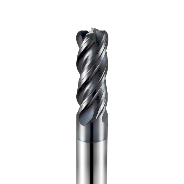
We often see shops run premium cutters on high-end machining centers yet still suffer poor tool life. The problem almost always traces back to holder selection and neck clearance design. While high-feed geometry directs most forces up the spindle axis, high table travel speeds amplify microscopic vibrations at the toolholder connection.
Maximizing high-feed roughing requires dialed-in holder rigidity and proper back-draft clearance. High-speed transitions into sidewalls can trigger deflection and sudden tool breakage if holder clamping is weak. Choosing a purpose-built end mill for hardened steel with relieved neck geometry—paired with rigid clamping—ensures smooth, multi-hour cycle times without chipping.
Shrink-Fit vs. Hydraulic Tool Holders: Controlling Runout During Interrupted Cutting
We always recommend keeping dynamic tool tip runout under 3 microns (0.003 mm) when roughing hardened tool steel. Shrink-fit holders offer exceptional rigidity, compact nose profiles, and balanced clamping for deep-cavity clearance. However, they lack internal dampening, meaning heavy shock loads from interrupted cuts transfer directly into the brittle carbide flutes.
High-precision hydraulic holders feature an internal fluid membrane that acts as a natural shock absorber against high-frequency chatter. Their only drawback is a bulkier snout profile, which can limit clearance in tight cavities. For heavy interrupted cuts in open areas, hydraulic holders significantly extend the working life of hardened steel end mills; for tight cavities with long reaches, slim shrink-fit holders remain the top choice.
Preventing Tool Deflection in Deep-Cavity Machining: Real-World Overhang Data
Tool overhangs of 4D, 5D, or 6D are common when hogging out large stamping or die-cast cavities. In our 58 HRC shop tests at 5D overhang (e.g., a 10 mm cutter extended 50 mm), traditional deep-cut side milling caused up to 0.08 mm of elastic tool deflection at the cavity floor. This created severe wall taper and left inconsistent stock for finishing passes.
Switching to high-feed milling under identical overhang reduced radial deflection to under 0.015 mm by directing forces axially into the spindle. This rigid cutting posture maintains accurate pocket geometry and prevents lateral chatter micro-fractures. Programming shallow step-downs with stub-flute, long-reach end mills designed for hardened steel gives you a reliable, productive process even at extreme reaches.
Troubleshooting Common On-Site Machining Accidents: Root Causes of Tool Breakage and Pull-Out When Milling Hardened Steel
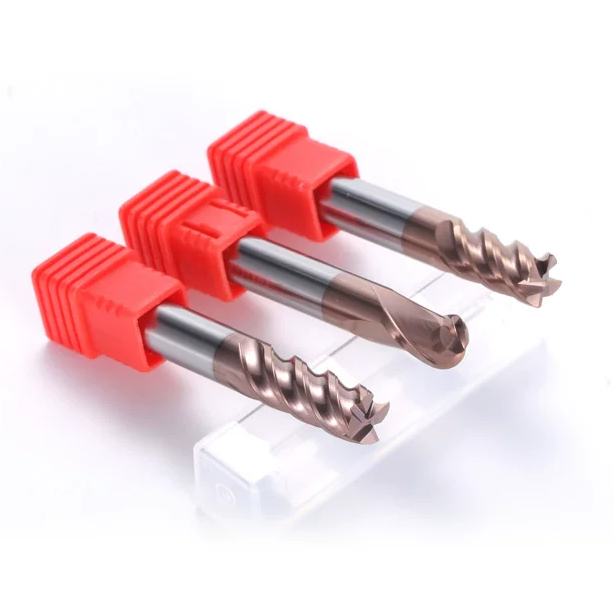
When milling hardened steel above 50 HRC, tool breakage and pull-out happen in a split second. Operators often blame inconsistent raw material hardness or tool quality. However, our shop-floor root-cause investigations reveal that material defects are rarely the culprit. Over 90% of failures stem from sudden cutting spikes and degraded chip evacuation in deep pockets.
Tool pull-out is especially dangerous under heavy cutting resistance. If holder clamping force degrades or a worn collet is used, high-frequency harmonics cause the cutter to unscrew along its flutes. The tool plunges uncontrollably, resulting in a sudden spindle crash. Preventing these failures when running an end mill cutting hardened steel requires dynamic corner deceleration, dedicated dry air blasts, and spotless toolholder tapers.
Failure to Decelerate at Corners Causes Instantaneous Load Spikes in High-Feed Milling
High-feed milling runs at aggressive table speeds, but transitioning into an internal 90° corner causes the tool engagement angle to spike from 30° to over 90°. Because machine axis acceleration exhibits minor latency, the effective chip load multiplies instantly. On-site spindle torque monitoring reveals that instantaneous loads frequently surge to three times normal levels during corner engagement.
For ultra-fine sub-micron carbide, this unbuffered shock easily fractures the corner radius. We strongly recommend enabling CAM arc-filtering to replace sharp turns with smooth roll-in paths, combined with a 30%–50% feed-forward deceleration 1D ahead of the corner. Easing cutting pressure allows your end mill for hardened steel to maintain high-feed efficiency through complex pocket geometry without chipping.
Poor Chip Evacuation During Traditional Roughing Leads to Re-Cutting and Premature Wear
In deep-slot side milling, chip evacuation space is severely restricted. Work-hardened chips produced from 60 HRC stock are razor-sharp and 2–3 HRC harder than the raw workpiece. If compressed air fails to clear the pocket, hot chips get dragged back into the cut, jamming between the flank face and sidewall. This destructive re-cutting produces irregular flaking along the primary flutes.
Re-cutting ruins machined wall finishes and rapidly strips away the protective coating, destroying the cutter’s red-hardness. For cavity depths within 2D, high-pressure external air manifolds clear chips effectively. Once pocket depths exceed 3D, we recommend switching to through-tool air end mills for hardened steel. Core-directed air blasts evacuate chips instantly, preventing catastrophic chip recutting.
Adjustments to Substrate and Cutting Edge Design as a Carbide End Mill Manufacturer
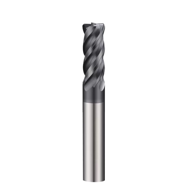
Every shop-floor milling strategy ultimately relies on microscopic tool geometry and substrate metallurgy. As a carbide end mill for hardened steel manufacturer, we know high-feed milling and conventional side milling demand completely different cutter designs. High-feed roughing requires extreme shock resistance and core rigidity, whereas side milling demands flank wear resistance and torsional stiffness along long flutes.
No single tool geometry can excel at both deep side milling and high-feed roughing in 60+ HRC steels. If you are processing hardened mold blocks, you can optimize output by reviewing your substrate grain size, edge hone profile, and high-temp coating specs. Matching your tool geometry to the specific cut path unlocks maximum machine productivity.
0.2µm Ultra-Fine Grain Substrate and Negative Rake Edge Honing for High-Feed and Traditional Milling
Machining hardened steel requires balancing hardness against fracture toughness. To handle the interrupted shock loads of high-feed cuts, we utilize 0.2–0.4 µm ultra-fine tungsten carbide with optimized cobalt distribution. This provides over 93 HRA hardness while keeping fracture toughness (KIC) high, preventing micro-cracks from propagating along grain boundaries during heavy roughing passes.
For cutting edge micro-geometry, we replace sharp positive rakes with a 2° to 5° negative rake combined with controlled edge honing. If you are experiencing micro-chipping on initial engagement, check your edge prep radius (ideally 10–18 µm). Controlled honing strengthens the cutting edge, enabling your end mill for hardened steel to absorb hardness variations across the hardened block.
Coating Selection Standards for HRC65 Roughing End Mills Tailored for Mold Roughing
When roughing hard mold steels, cutting temperatures regularly exceed 900°C, causing standard PVD coatings to oxidize and delaminate. For our custom hrc65 roughing end mills, we apply high-aluminum, silicon-doped nanocomposite coatings (such as AlCrSiN or TiSiN). Silicon forms a dense, self-healing SiO2 barrier under heat, raising oxidation resistance past 1,100°C while lowering friction during dry cutting.
Ultimately, tool design, cutting parameters, toolholders, and chip clearing form an integrated manufacturing chain. If you are struggling with tool life on a specific hardened steel grade, or need to eliminate chatter in deep cavities, you can share your material specs, hardness, and part drawings with us. We will help you analyze the cutting forces and build a reliable milling solution for your shop.






