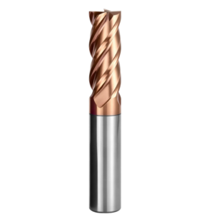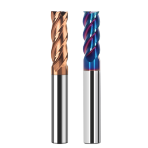
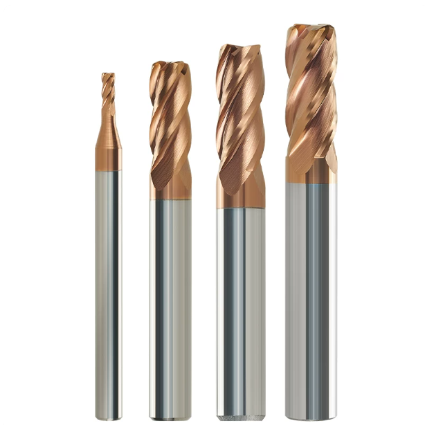
Last month, a precision mold customer in Stuttgart, Germany sent us high-frequency audio from their shop floor. A 5-axis machining center was running corner rest-milling inside a vacuum-hardened automotive stamping die. The workpiece was 1.2379 (D2) tool steel, heat-treated to HRC 62.
The shop ran standard four-flute, constant-helix carbide end mills pulled straight from their stockroom. Three minutes into the cut, the smooth hum turned into a high-pitched spindle shriek. When the operator hit the emergency stop, the sidewalls showed heavy chatter waves, and two consecutive flutes had suffered severe shell-like micro-chipping.
As an engineering and manufacturing team, we have resolved this exact failure across European and North American machine shops hundreds of times. In pre-hardened steels, standard constant-helix tools work reliably if you tune speeds and feeds. But in HRC65 mold steel milling, that fixed flute pitch becomes an immediate liability.
A constant helix forces each flute to engage and exit at identical time intervals. These periodic force pulses repeatedly excite the tool tip at a single base frequency. In deep cavities with long overhangs, this matches the setup’s natural frequency and triggers violent resonance. Shops end up cutting feed rates in half or switching to slow electrical discharge machining (EDM).
Our cutting tests show that harder carbide substrates or ultra-fine grains only treat the symptom. High shear resistance requires altering the cut’s fundamental dynamics. By optimizing variable helix end mill geometry and uneven flute spacing, you break the entry phase relationship and disrupt periodic force peaks. This cuts off resonance at the source and reduces hardened steel end mill wear.
Does an asymmetrical helix solve every high-hardness challenge on its own? And why do some shops still see witness lines and chipping after upgrading to an advanced carbide end mill for hardened steel?
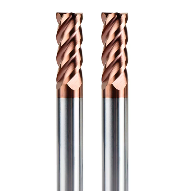
Real-World Machining of Hardened Molds: Why We No Longer Recommend Constant-Helix End Mills for Milling HRC65 Mold Steel
When machining die-casting or stamping dies near HRC 65, material shear behavior changes drastically. Operators often trust standard four-flute 35° or 45° constant-helix end mills, counting on sub-micron carbide grades to resist bending forces. Yet across high-precision shrink-fit setups, constant-helix geometries suffer sudden tool life collapse the moment they engage hardened core stock.
At high Rockwell levels, plastic deformation gives way to localized micro-brittle fracture. The symmetric engagement of a constant helix generates relentless cyclic impact rather than clean shearing. We have discontinued standard constant-helix designs for roughing and semi-finishing in HRC65 mold steel milling, moving all production lines to dynamic, chatter-suppressing geometries.
The Destructive Power of Harmonic Resonance: How Periodic Cutting Forces Lead to Chipping in Constant-Helix End Mills
Inspecting worn constant-helix tools rarely reveals smooth abrasive flank wear. Instead, you see shell-shaped micro-chipping spaced along the cutting flutes. A constant helix locks circumferential entry angles and axial shear directions into a rigid cycle. Higher hardness creates sharper impact spikes, feeding uniform shock waves straight back into the tool core and spindle.
Our dynamic dynamometer data proves that symmetric tools hit dangerous deflection spikes within seconds. Once they trigger the system’s natural frequency, harmonic resonance doubles instantaneous cutting forces in microseconds. Brittle carbide grains crack under this cyclic fatigue. The chatter waves on your mold walls are physical scars left by the tool fighting its own harmonic resonance.
Machine Tool Rigidity and Spindle Vibration: A Comparative Study of Constant-Helix vs. Variable-Helix End Mills at High Aspect Ratios
We ran benchmark stress tests on a high-speed machining center with an HSK-A63 spindle. The workpiece was hardened die steel, the overhang ratio reached L/D = 4.5, and axial depth of cut was 1.5 times the tool diameter. As we raised surface footage with a constant-helix tool, spindle accelerometers showed vibration climbing rapidly with table feed. The setup hit its dynamic limit on the third pass, snapping the tool at the shank.
We repeated the exact run using an engineered variable helix end mill with identical holder balance and cutting parameters. Vibration root-mean-square (RMS) readings dropped immediately into the stable green zone. Staggering flute entry and exit angles broke the excitation rhythm, giving the tool assembly built-in damping. Proper flute geometry compensates directly for mechanical rigidity limits in deep-reach setups.
From Chip Evacuation to Cutting Resistance: Typical Failure Modes of Constant-Helix End Mills in Side-Milling HRC50+ Hardened Steel
In HRC 50+ finish side-milling, chips do not curl into continuous ribbons. They shear off as high-temperature, pulverized micro-granules. A constant-helix tool offers uniform flute pockets, but this causes fine dust to stall during shallow radial cuts. Trapped grit grinds between the heel and the cut wall, creating instant thermal friction spikes.
This friction leads directly to catastrophic tool failure. Flutes show thermal stress cracks and micro-chipping along the edge rather than uniform flank wear. Because a constant helix cannot break up radial force vectors along the tool axis, cutting pressure stays purely unidirectional. Elastic deflection escalates into mechanical fatigue, causing severe hardened steel end mill wear in minutes.
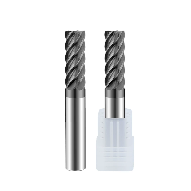
A Micro-Geometric Analysis of Cutting Edges: The True Mechanism Behind Variable Helix End Mill Geometry in Suppressing Chatter and Tool Damage
Machinists often attribute vibration resistance solely to advanced coatings or tough carbide grades. In practice, micro-geometry dictates your cutting dynamics. During our 5-axis grinding R&D, deconstructing cutting-force phase superposition under extreme shear resistance was our toughest hurdle. Symmetrical cylindrical flutes force shear force peaks to hit the exact same spatial location on every revolution. This rapidly drives microscopic cracks deep into the carbide substrate.
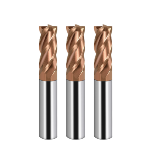
By applying an asymmetrical helical topology to flute grinding, we convert uniform axial leads into dynamic gradient angles. Engineered for hardened steels, this variable helix end mill geometry does not aim for the theoretical impossibility of zero vibration. Instead, it breaks the phase periodicity between successive cutting flutes. Dispersing harmonic energy across multiple frequencies provides brittle carbide corners the safety margin they need to survive severe cutting loads.
Combining Variable Helix Angles with Unequal Tooth Pitch: Disrupting Natural Frequencies to Eliminate Long Reach End Mill Chatter
Machining deep mold cavities past 5xD often causes noticeable tool tip wander at sharp corners. Running a variable helix pair like 38°/41° works well at standard lengths, but flexibility rises sharply as reach expands. Lead variation alone cannot suppress deep-cavity harmonics. Our cutting tests show you must pair unequal helix angles with an asymmetric circumferential pitch (such as 88°–92°–89°–91°) to break the symmetric pulse rhythm entirely.
This dual-asymmetry approach forces a continuous phase shift between the wave left by the leading tooth and the cut of the trailing tooth. It eliminates the conditions needed for regenerative chatter to develop. For deep-cavity clearing, this geometry effectively suppresses long reach end mill chatter and stops edge spalling. The trade-off is minor: chip thickness per flute varies slightly, requiring tight grinding-wheel dressing tolerances and precise flute indexing.
Variable Core Thickness and Flute Depth for High-Hardness Materials: Enhancing Bending Rigidity While Preventing Flute Clogging
When tools break, shop supervisors often ask for a thicker core. In high-hardness steels, however, core cross-section and chip gullet volume sit on a knife-edge. Pushing core diameter past 70% boosts bending stiffness, but flat flutes trap fine, abrasive debris. This trapped metal dust undergoes secondary grinding in the gullet, generating severe transient radial forces that snap the end mill.
We solve this using a parabolic, reverse-tapered core paired with variable-depth flutes. The cutting tip features a smooth, slightly concave gullet that keeps dry, high-pressure air moving freely. Toward the shank, the core area thickens along a controlled gradient. This geometry prevents heat-trapping chip pack at the tip while providing sufficient section modulus where bending moments peak.
Negative Rake Angles, T-Lands, and Edge Honing: How Variable Helix Designs Mitigate Hardened Steel End Mill Wear
Sharp, positive rake angles fail within seconds on HRC 60+ steel because brittle carbide cannot support heavy tensile loads. We grind a negative rake between -8° and -12°, matched with a 0.03 mm to 0.05 mm negative T-land chamfer. While this raises radial push, it redirects primary cutting forces into compression. This takes full advantage of carbide’s high compressive strength.
Edge honing and T-lands must be dynamically paired with the changing helix angle. On smaller helix sections, we widen the negative T-land angle to handle entry shock. On larger helix flutes, we tighten the honing radius to reduce tangential drag. This balanced axial loading curbs micro-chipping, ensuring hardened steel end mill wear develops only as controlled, uniform flank abrasion.
Implementing Cutting Parameters and Strategies on the Shop Floor: Practical Feed, Speed, and Path Planning for Carbide End Mills in Hardened Steel
Relying on traditional roughing paths will destroy advanced edge preps and high-heat coatings in minutes. Published handbook feeds and speeds rarely reflect actual dynamic shop floor conditions. Hardness spikes across tool steel blocks, machine acceleration limits, and holder deflection can quickly push programmed feeds past safe boundaries.
Our hard milling principle centers on three rules: limit arc of contact, keep chip temperature stable, and maintain constant chip load. When optimizing production lines for clients, theoretical metal removal rate matters far less than steady cutting forces. Choosing a purpose-built carbide end mill for hardened steel is only step one; your actual tool life depends on dialing in your radial-to-axial depth ratios at the controller.
Trochoidal Milling and High-Speed Machining (HSM): Optimizing Depth-of-Cut Ratios to Maximize Variable Helix Performance
Slotting hardened steel cavities at full cutter width leads straight to edge fracture. For steel over HRC 60, switch to dynamic trochoidal paths or high-speed, light radial passes. We keep radial depth of cut (ae) strictly within 4% to 8% of cutter diameter, while taking axial depths (ap) up to 1.5 to 2 times tool diameter. This thin-chip method evacuates heat inside red-hot chips, leaving the workpiece cool.
Variable helix cutters deliver their best performance within this light radial engagement window. Keeping radial contact angles below 30 degrees minimizes entry impact, allowing the unequal flutes to damp residual axial force ripples. Keep a close eye on your machine’s look-ahead interpolation. If corner deceleration drops feed per tooth below your edge hone radius, clean cutting degrades into abrasive rubbing.
Controlling Overhang and the Overhang-to-Diameter Ratio: Managing Long Reach End Mill Chatter through Toolholder Selection and Dynamic Balancing
Clearing deep die pockets often forces tool overhang ratios to 4:1, 6:1, or higher. When chatter starts, operators often drop spindle speed, which can drag the cut straight into a low-frequency torsional resonance band. During troubleshooting, our first step is replacing standard ER collets with shrink-fit or rigid hydraulic chucks. This cuts interface deflection and ensures balance grades reach at least G2.5 at 20,000 RPM.
A balanced toolholder forms your first line of defense against tool deflection. Combined with asymmetrical flutes that break up harmonic excitation, a stiff, high-damping holder limits long reach end mill chatter and holds tip runout within microns. Where clearance demands extreme reach, we use necked-shank blanks. Sacrificing a small amount of chip space yields significantly higher torsional stiffness.
Cooling and Thermal Crack Control: Dry Machining, Air Cooling, or Minimum Quantity Lubrication (MQL)?
Flooding high-hardness cuts with liquid coolant often shortens tool life. Flutes enter and exit hardened steel at high RPM, spiking contact temperatures beyond 800°C before cold fluid instantly quenches the edge. This severe thermal shock forms comb-like micro-cracks across AlTiN or AlCrN coatings, causing premature flaking.
For tool steels at HRC 55 and above, high-pressure dry air or external MQL works best. Compressed air (at 0.6 MPa or higher) clears hard chips instantly so they are not recut within tight cavities. MQL delivers a microscopic lubricant film to ease chip sliding without thermal shock. Dry cutting may generate visible sparks, but it keeps cutting edges in a stable thermal state.
Troubleshooting Tool Wear and Failure: Assessing Wear Progression and Tool-Change Thresholds for Hardened Steel
On the shop floor, operators often wait for a piercing spindle squeal or out-of-spec parts before hitting the emergency stop. In hardened steel, this delay causes broken shanks or damaged mold cavities. Above HRC 60, tool degradation is non-linear; it has a quiet incubation stage followed by sudden failure. Once edge rounding exceeds a critical threshold, cutting resistance spikes within minutes.
In our lab and on-site testing, we never judge tool life by the machine load meter alone. We inspect micro-edge geometry under a stereomicroscope. Tracking flank wear bands, notch wear lines, and edge micro-fractures lets you predict true hardened steel end mill wear. Reading tool wear patterns against real-time spindle feedback stops scrap at the source.
Flank Wear, Chipping, and Notching: Distinguishing Between Normal Tool Wear and Impact Damage Caused by Machine Resonance
A 50x optical magnifier reveals the exact mechanics behind your tool wear. Normal progressive wear shows up as a flat, uniform, silver-gray abrasion band (VB) along the cutting relief. Notch wear at the depth-of-cut line comes from surface work-hardening or abrasive scale. These are standard mechanical friction modes within normal cutting limits.
If the edge shows jagged chipping or peeled coating flakes, friction is not the culprit. This damage flags self-excited harmonic resonance. High-frequency cyclical forces deliver thousands of micro-impacts per second, cracking the cobalt binder phase through shear fatigue. Treating impact chipping as abrasive wear and dropping surface speed only traps your variable helix end mill in a worse resonance band.
Thermal Hardness Degradation vs. Mechanical Fatigue: A Metallographic Comparison of Cutting Edges After 4 Hours
We ran 4-hour continuous cuts on hardened D2 (1.2379, HRC 62) and analyzed the cutting edges under a scanning electron microscope. Constant-helix cutters showed rapid mechanical fatigue followed by thermal breakdown. Constant-frequency impacts generated micro-cracks in the carbide substrate within two hours. Trapped friction heat pushed local edge temperatures past 900°C, softening the cobalt binder and collapsing the flutes.
Under identical speeds, feeds, and air cooling, the variable-helix cutter showed a clean metallurgical profile. Asymmetrical phase angles broke the periodic impact cycle, stopping transverse fatigue cracks and spreading heat evenly across the flutes. Flank coatings showed minor oxidation, but substrate core hardness stayed intact. A properly engineered carbide end mill for hardened steel stops cyclic impacts from triggering thermal failure.
Controlling Tool Runout (TIR): Why Radial Runout Exceeding 3µm Negates All Geometric Advantages in an HRC65 End Mill
Shops often check tool shanks with an indicator, see 0.005 mm, and call it good. They forget to measure Total Indicated Runout (TIR) at the actual cutting tip. In soft steels, minor runout only hurts surface finish. In hard milling, tooth feed (fz) runs between 0.015 mm and 0.03 mm. A 3–5 µm runout overloads one flute by 30% to 50% while the opposite flute cuts air.
Mounting a premium HRC65 end mill in a sloppy holder ruins its balanced cutting dynamics. The overloaded tooth chips on its first entry pass. Once that flute chips, impact loads on the remaining teeth spike instantly. We always mandate tool tip runout under 3 µm; otherwise, advanced flute geometry cannot protect your cutting edges.
Case Studies and Custom Tool Selection: Technical Support Insights from an HRC65 Carbide End Mill Manufacturer
Over years of troubleshooting across North American and European toolrooms, clients rarely ask us about cutter prices. Their main question is whether the machine spindle will run unattended until the next shift. High-hardness milling requires balancing machine rigidity, holder damping, trochoidal toolpaths, and micro-edge prep. At HRC 60 and above, a weak link anywhere in the setup destroys the cut.
As an HRC65 carbide end mill manufacturer, we know catalog speeds and feeds only reflect perfect test setups. Machine wear, controller look-ahead limits, and part shapes vary from shop to shop. Machinists must adapt parameters to real conditions. Turning field failure data into tailored tool geometries is what makes hard milling profitable and stable.
Clearing Deep Cavity Corners: How an HRC65 End Mill Variable Helix Eliminates Mold Transition Steps
Last year, a Tier 1 automotive stamping die supplier struggled with deep 80 mm pocket corners in HRC 62–64 tool steel. Their standard 4-flute, constant-helix ball-nose cutters left 0.02 mm witness steps and chatter marks at step-over junctions. Two bench hands spent hours polishing out these marks with stones, backing up die assembly lines.
We checked their shrink-fit holder runout and switched the toolpath to an HRC65 end mill variable helix corner-radius cutter with a 4° neck clearance. The variable lead smoothed out the transient force spikes typical of sharp cornering. This stabilized sidewall finish below Ra 0.4 µm, wiped out tool-engagement marks, and eliminated manual bench polishing.
Special Scenarios Beyond Standard Catalogs: Designing a Custom Solid Carbide End Mill for Deep Reach and Tight Corners
Standard tool catalogs only cover common length-to-diameter ratios. When reach stretches past 5xD or 7xD, or when a 15 mm deep pocket demands a tiny 0.5 mm corner radius, standard end mills deflect and break. Resolving these clearance challenges requires recalculating the tool blank’s cross-sectional moment of inertia to balance bending stiffness against chip clearance.
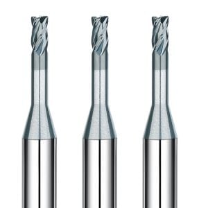
Engineering a custom solid carbide end mill is the only reliable fix for these deep pockets. We map the cavity’s 3D surfaces and grind dual-tapered necks supported by parabolic cores exceeding 75% of tool diameter. Flutes receive a nano-mirror polish to evacuate fine chips under dry air blasts. This stiff profile minimizes tip deflection under deep reach.
Tool Selection Checklist: Matching Hardness Gradients, Spindle Interfaces, and Depth
Review your tooling approach against your current machine setup:
- If you are using BT40 spindles or standard collet chucks past 3xD reach, reduce surface footage and switch to shrink-fit or hydraulic holders. Keep tip runout under 3 µm to prevent single-flute shock loads.
- If you are cutting steels past HRC 60, stop using constant-helix end mills. Upgrade to variable helix flutes with negative T-lands and unequal spacing to break harmonic resonance in HRC65 mold steel milling.
- If you are fighting corner chipping or erratic tool life, switch to dynamic trochoidal paths with light radial step-overs and dry compressed air. This stops thermal fatigue cracks from forming on the flutes.
No single end mill delivers peak tool life without considering machine rigidity and toolpath strategy. If you are setting up rest-milling operations on hardened cavity blocks or dealing with chatter marks on deep sidewalls, we can help. Send over your 3D models, hardness specifications, and spindle details, and we can map out a tooling package tailored to your shop.