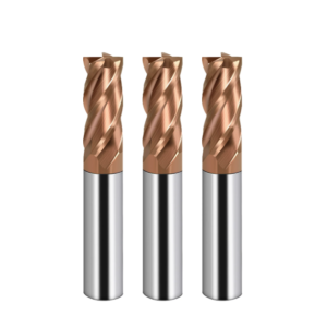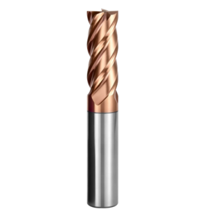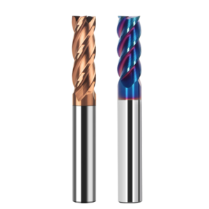

Last month, a precision injection mold client in Ohio sent us a video of an abrupt spindle alarm. Their five-axis machining center had just passed dynamic balancing checks. Yet, a standard carbide end mill suffered catastrophic micro-chipping along its entire primary cutting edge in under eight minutes while finish-milling a D2 mold slide hardened to 63–65 HRC. The resulting high-frequency screech immediately tripped the spindle overload protection.
The shop floor manager assumed the carbide substrate was too brittle or the AlTiN/TiSiN nano-coating had delaminated. However, our confocal microscope inspection revealed the real issue right away. This failure was not caused by material defects or poor coating adhesion. It was a textbook mismatch between workpiece hardness and basic end mill geometry.
Over 16 years of supporting mold and aerospace shops across North America and Europe, we have seen this failure mode countless times. Operators accustomed to machining pre-hardened steels like P20 or NAK80 rely on sharp, positive cutting edges. Above 60 HRC, that cutting mechanism fails completely. The metal loses almost all ductility, generating massive mechanical shock and interface temperatures exceeding 900°C. Under these loads, sharp edges are crushed within milliseconds. Survival in 65 HRC tool steel requires rethinking three physical pillars:
- End mill cutting edge geometry: Replace positive rakes with a rigid negative T-land and controlled edge honing to absorb shock under compression.
- End mill rigidity: Push core thickness to 65%–70% of the tool diameter to lock radial deflection down to the micron level.
- End mill flute geometry: Use engineered variable pitch spacing to break harmonic chatter frequencies before they propagate.
Every micron of edge honing and every degree of wedge reinforcement dictates real-world end mill tool life. When cutting ultra-hard metals, are you truly shearing the chip, or are you just using the machine spindle to ram carbide into hardened steel?
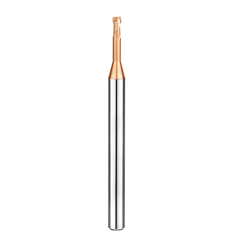
Why General-Purpose End Mills Fail on Hardened Steel: Redesigning Geometry Based on Failure Mechanisms
Most machinists have witnessed this exact scenario on the shop floor. An operator loads a high-performance “general-purpose” four-flute end mill to cut hardened cold-work tool steel. The program clears just two cavity corners before the spindle load meter spikes. Upon inspection, the cutting edges are already chipped beyond recognition. Operators often blame insufficient coolant flow or aggressive feeds, but our failure analysis shows the true culprit is the tool design itself.
In soft steel, a tool shears and curls ductile chips using a sharp wedge angle. Hardened steel lacks plastic deformation capacity, turning cutting into a high-pressure mechanical stripping process. General-purpose cutters with thin edge wedges and open flutes cannot handle these extreme reactive shock loads. This fundamental conflict is why we must rebuild hardened steel end mill geometry from the ground up for extreme-hardness milling.
Addressing the Typical Failure Mode for 60–65 HRC Hardened Mold Steel: Micro-chipping Rather Than Normal Wear
When troubleshooting tools for powder metallurgy stamping dies, we constantly see teams expect gradual flank wear. When milling 60–65 HRC hardened die steel, normal abrasive wear rarely happens. The martensitic matrix is packed with hard carbides. As the tool engages the steel at high surface speeds, the microscopic edge faces severe cyclic mechanical impact, especially in interrupted cuts.
If the cutting edge lacks cross-sectional mass, the sharp tip fractures almost immediately upon entry. Under a microscope, this shows up as jagged micro-chipping rather than a smooth wear land. Once a chip forms, cutting resistance spikes instantly and ruins the entire cutting flank. Our primary goal for hardened steel end mill geometry is never mere sharpness; it is shifting the cutting edge stress state from tension into pure compression.
Physical Compromises in End Mill Geometry Driven by Soaring Cutting Resistance and Shear Heat
Shop supervisors often ask if we can design a hardened steel cutter that feels free-cutting yet never chips. Basic physics forces hard compromises here. In hard milling, severe shear strain converts over 80% of cutting energy into localized heat, quickly pushing cutting zone temperatures past 900°C. A sharp positive rake angle will soften and collapse under these extreme forces and temperatures.
Redesigning an end mill geometry requires calculated engineering trade-offs. We replace free-cutting sharp edges with reinforced, passivated micro-lands to support extreme loads. We also shallow out the flutes to build maximum bending resistance, sacrificing chip pocket clearance. While this heavy geometry might look resistive compared to aluminum cutters, it gives the solid carbide core the structural support required to survive extreme cuts.
Our Primary Geometric Adjustment Strategies for Addressing Thermal Deformation and Intense Reaction Forces
When fixing tool deflection and chipping on customer shop floors, we inspect core mass and clearance angles before touching feed rates. Severe cutting resistance causes significant elastic spring-back after the cutting edge passes. Increasing relief angles blindly thins the supporting edge structure. Conversely, setting relief too tight generates severe friction, creating thermal expansion that jams the cutter in the cut.
Our field-tested solution is combining a heavy core with a stepped dual-relief angle and a negative rake face. This directs primary shear loads into the rigid carbide core, turning impact forces into uniform compressive loads. The narrow primary relief maintains edge strength, while the secondary relief provides clear escape room for elastic recovery. This specific HRC65 end mill for hardened steel geometry keeps tools running stable even under minimal lubrication conditions.
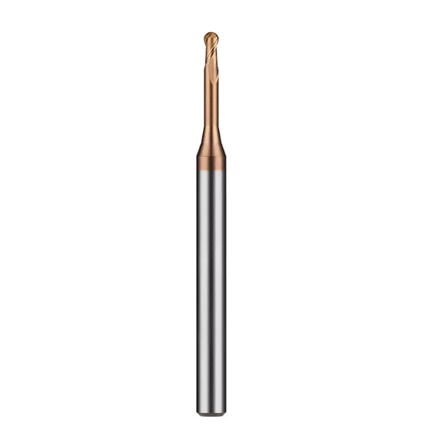
The Critical Trade-off Between Chipping Resistance and Heat Dissipation: Practical Design of End Mill Cutting Edge Geometry
Under 200x magnification, severe tool failure on 62 HRC steel is almost always concentrated within a 0.05 mm zone along the cutting tip. Machinists often assume spindle speeds were set too high. In reality, the issue is an improperly supported microscopic stress triangle at the cutting edge. On hardened steels, the edge acts less like a sharp razor and more like an anvil enduring thousands of high-frequency mechanical shocks per minute.
Tool survival depends on balancing impact toughness against cutting friction heat. An overly sharp edge fractures under stress, while excessive honing spikes cutting resistance and traps heat inside the tool body. Mastering end mill cutting edge geometry is our foundational step to preventing premature chipping and catastrophic tool deflection in deep mold cavities.
Setting the Negative Rake Angle Range (-5° to -12°): Preventing Instantaneous Edge Failure
Tool geometries for 60+ HRC steels consistently feature negative radial rake angles. During tests on 1.2379 (D2) inserts in Germany, tools ground with neutral (0°) or positive rakes developed micro-chipping within ten minutes. Positive rakes place brittle carbide grains under direct tensile bending stress. Because cemented carbide has three times higher compressive strength than tensile strength, positive rakes expose the substrate to its weakest state.
Grinding radial rake angles from -5° to -12° directs cutting forces inward toward the solid carbide core. This leverages the substrate’s high compressive strength against heavy shock loads. However, dropping past -12° spikes cutting resistance and friction heat, causing low-frequency chatter on lighter machines. For stable mold finishing, keeping your end mill cutting edge geometry within -6° to -8° delivers the most dependable balance between edge strength and cutting load.
T-land Width and Edge Honing: Empirical Ratios Matched to Feed per Tooth (fz)
Grinding an accurate negative T-land is only half the battle; performance depends on matching the land width to your programmed feed per tooth (fz). We frequently see North American shops run a 0.08 mm T-land while feeding at only 0.02 mm per tooth. Under these conditions, the tool never cuts. Instead, the chamfer burnishes the work-hardened surface, generating intense frictional heat that ruins the cutting edge in seconds.
Our rule is maintaining a 1:1 to 1.5:1 ratio between T-land width and feed per tooth (fz). For a finishing cut at fz = 0.03 mm, keep T-land width strictly between 0.03 mm and 0.045 mm at a 10°–15° angle. Pair this with an 8–15 micron edge hone to remove microscopic grinding burrs. This optimized end mill cutting edge geometry creates a stable shear plane during chip formation and prevents micro-cracking at the tool tip.
Double Relief Angle Design: Preventing Severe Premature Wear Caused by Friction from Elastic Recovery
When machinists report premature flank wear, inspection often reveals a wide, burnished wear band. Steels at 65 HRC exhibit intense elastic recovery after cutting compression. Using a single large relief angle to clear this spring-back leaves the cutting tip dangerously thin and prone to snapping. Using a small single relief angle causes the spring-back material to rub against the flank, accelerating flank wear within minutes.
We solve this issue using a stepped double relief angle. The primary relief angle is ground tight at 6°–8° across a narrow 0.10–0.15 mm land, providing solid carbide mass directly behind the cutting tip. The secondary relief angle immediately opens to 12°–15°, providing instant clearance for material spring-back and thermal expansion. This geometry cuts friction heat dramatically and maintains tight tolerances during high-precision hardened steel end mill geometry applications.
Rigidity Equals Longevity—The Golden Balance Between End Mill Core Diameter and Flute Design
When troubleshooting poor surface finish on 60+ HRC steels, machinists usually check spindle runout and holder torque first. However, tool body deflection is the true culprit. Under high cutting speeds, radial forces spike rapidly at the tool overhang. Lacking sufficient cross-sectional bending stiffness, even minor deflection throws off programmed toolpaths, producing surface waviness and high-cycle edge fatigue.
Hard milling requires structural stiffness over deep chip clearance. Deep flutes designed for long ductile chips are completely counterproductive in hardened materials. Hard steels produce short, powdery chips inside a very shallow shear zone. Redesigning cross sections to increase end mill core diameter provides the physical backbone needed to prevent deflection and chatter under heavy side loads.
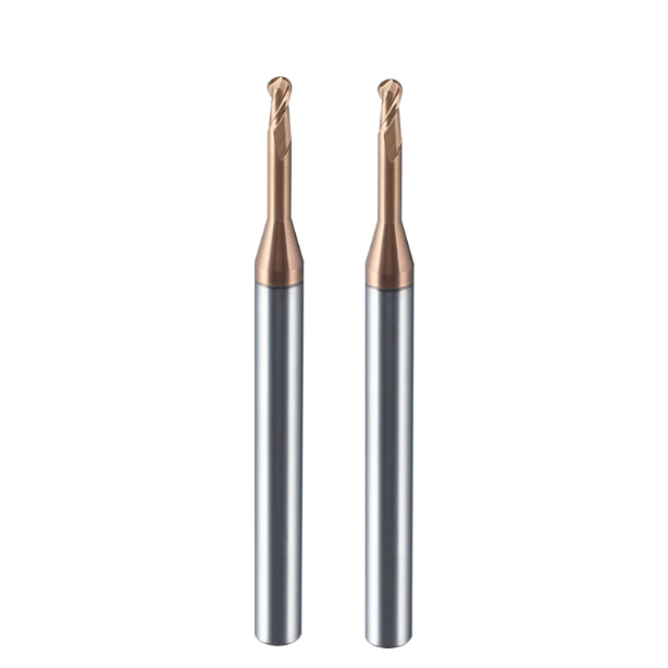
Maximizing Bending Rigidity by Increasing Core Diameter to 65%–70%
Standard tools use a 50% to 55% core ratio to clear large chips in heavy roughing. Our tests at a Detroit stamping die shop cutting 62 HRC D2 tell a different story. Raising the core-to-diameter ratio to 65%–70% cut tool tip deflection by nearly half. Because rigidity scales to the fourth power of core thickness, small core gains yield massive resistance against bending.
Pushing core thickness near 68% shrinks chip gullet space, but fits high-speed shallow cuts perfectly. Chip thickness in 60–65 HRC milling runs only a few microns per tooth. Deep chip pockets become unnecessary structural weak points that encourage tool bending. Retaining solid carbide along the center axis makes a rigid end mill core diameter essential for holding tight tolerances in deep cavities.
Flute Polishing for End Mill Geometry in Hardened Steel Machining (Chip Breaking and Shallow-Depth Conditions)
Hardened steel chips have zero ductility, turning into abrasive dust under severe shear heat. Flutes no longer need to roll long curls; they must clear hot debris through the shortest exit path. Traditional deep flute pockets create stagnation zones where abrasive particles trap heat. These trapped chips act like grinding paste, scouring flute walls and baking heat straight into the tool body.
On 5-axis CNC grinders, we program shallow arc profiles with smooth transitions. After fluting, mirror polishing drops surface roughness below Ra 0.1 microns. This eliminates grinding striations and removes microscopic anchors where hard dust could weld to walls. Optimizing end mill flute geometry ensures powdery chips eject immediately under high centrifugal forces and dry air blasts.
Static Deflection Calculations and the Impact of Actual Tool Stick-out on End Mill Rigidity
In deep cavity work, operators often run standard tools with excessive overhang to clear fixtures. Basic beam physics proves static deflection scales with the cube of stick-out length. Extending a tool from 3xD to 4xD more than doubles radial deflection under identical loads. This severe flex tilts the cutting edge, destroying carefully ground micro-geometries instantly.
To preserve maximum end mill rigidity, we engineer tools with reinforced necks, back-tapers, and short flute lengths. We limit cutting flutes to 1.5xD–2xD, supporting the rest with a heavy shank to damp high-speed spindle whip. Machinists should remember that every extra millimeter of stick-out costs tool life. Keeping overhang clamped to absolute minimum clearances protects overall setup rigidity.

Suppressing Chatter and High-Cycle Fatigue: Helix Angle and Unequal Flute Spacing
High-pitched screaming during hard milling signals that the tool is entering regenerative chatter. At 60+ HRC, if tooth impact frequency hits machine natural harmonics, chip thickness variations compound rapidly. These alternating loads destroy sidewall finishes and trigger micro-cracks along carbide grain boundaries. This continuous high-cycle fatigue degrades the tool long before normal abrasive wear sets in.
Dumping spindle speed to stop vibration is an inefficient compromise. The real engineering fix requires breaking the phase alignment of cutting forces at the source. By altering flute spacing and the primary end mill helix angle, we scatter impact peaks during tool grinding. This disrupts synchronous harmonic feedback loops before resonance can destabilize the cut.
Empirical Trade-offs Between Axial Load and Radial Rigidity (End Mill Helix Angle: 35° to 45°)
In aluminum, 45° to 50° helix angles clear chips smoothly with high upward shear lift. However, testing 63 HRC 1.2379 die inserts in Germany revealed serious risks with high helixes. While large angles reduce radial side loads, they convert excess cutting force into axial pull-out loads. Under heavy hard milling feeds, slight axial tool creep quickly throws off floor depth tolerances.
Shop-floor data shows a 35° to 45° end mill helix angle delivers the most reliable mechanical compromise. Dropping below 30° minimizes axial pull but concentrates heavy shock loads radially, encouraging wall deflection. Keeping base helix angles between 38° and 42° provides smooth entry shear while locking axial forces safely within tool holder pull-out limits.
Variable Helix & Unequal Pitch: Disrupting High-Frequency Shop-Floor Resonance
Even dynamically balanced setups produce washboard chatter marks when running symmetrical 4-flute or 6-flute cutters in hard steel. Symmetrical flutes hit the workpiece at identical time intervals, feeding a steady harmonic excitation frequency into the spindle. Each tooth hits the wave left by the previous tooth, amplifying resonance across the cut.
We break this pattern by combining unequal index spacing with variable helix angles. We offset flute index angles slightly (such as 88°-92°-89°-91°) and vary the end mill helix angle across flutes (like 38° and 41° pairs). This shifts tooth entry timing, causing wave patterns from successive cuts to cancel out through destructive interference.
Dynamic Feedback on End Mill Helix Angles in Trochoidal Milling and High-Speed, Shallow-Cut Operations
Modern CAM trochoidal paths use light radial cuts (ae 5%–10%) and deep axial engagement (ap 1.5xD–2xD). Under this engagement model, cutting edges face rapid-fire impact cycles rather than constant side pressure. Entering and exiting the cut at high frequencies places extreme demands on the cutter’s dynamic torsional stability.
An unbalanced end mill helix angle across deep cuts causes cutting edges to twist and snap back erratically. This micro-level stick-slip motion accelerates chipping along the outer corners. Pairing moderate helix angles with variable spacing smooths out radial load spikes during trochoidal arc entries, letting machine servos handle millisecond load changes smoothly.
Flute Count Selection and Machining Efficiency: The Impact of End Mill Flute Count on Feed Rate and Stability
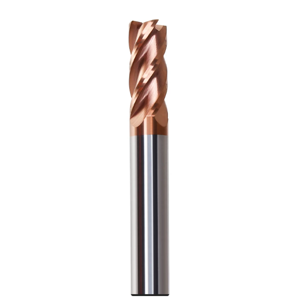
Many shops play it too safe on 60+ HRC steels. Operators often default to a standard 4-flute cutter and drop the feed rate to avoid breakage. However, running low flute counts at high spindle speeds caps table feed rates severely. Forcing feed per tooth to hit production targets spikes shock loads, chipping edges on hard workpiece skins.
Choosing flute count is never a one-dimensional choice. Adding flutes increases cross-sectional stiffness and contact overlap, but it shrinks chip gullet space dramatically. Balancing axial depth, cut width, and chip clearance is essential. Optimizing your end mill flute count is the secret to cutting cycle times in hardened steel without risking catastrophic tool breakage.
Application Boundaries for 4-Flute, 6-Flute, and Multi-Flute End Mills in Hard Milling (Side Milling vs Face Milling)
Testing on 64 HRC hot-work die inserts in Sweden proved 4-flute cutters struggle during shallow profiling. With wide gaps between cutting edges, each tooth re-entry hits the steel with an aggressive mechanical shock wave. Stepping up to 6 or 8 flutes keeps multiple teeth engaged continuously. This stabilizes spindle torque ripple and drops sidewall surface finishes below Ra 0.2 μm.
However, high flute counts fail when axial depths spike. In slotting or tight corner clearing, narrow gullets on multi-flute tools pack with hot chips, causing rapid chip welding. While 4-flute cutters run slower table feeds, their deeper flutes carry chips away safely. Match your end mill flute count to the cut: pick multi-flute for shallow profile finishing, but drop back to 4 flutes for deep corner cleanup.
Thin-walled molds and deep-cavity hardened parts: How multi-flute, high-feed strategies reduce per-tooth load
Machining thin-walled, heat-treated dies is challenging because 62–65 HRC steels have zero plastic yield. Heavy single-tooth chip loads exert immense normal cutting forces that flex fragile walls. When thin sections spring back into the cutter, severe pinching crushes the cutting edge. This failure mode scraps expensive mold inserts right on the final finishing pass.
The engineering fix pairs high flute counts with high table speeds and tiny chip loads. Running 6 or 8 flutes lets you drop feed per tooth down to 0.015–0.025 mm while keeping feed rates fast. This micro-shearing action minimizes lateral push against cavity walls. Leveraging a rigid end mill flute count protects delicate mold features from deflection while holding tight tolerances.
Mitigating Operational Risks When Selecting High-Rigidity, Multi-Flute Tools in Chip-Evacuation-Constrained Environments
Multi-flute tools carry a major design limitation: cramped chip pockets. While investigating broken solid carbide tools at a UK aerospace supplier, spindle logs showed no sign of chatter. Instead, hard micro-chips packed tightly into narrow flutes inside an enclosed pocket. The resulting hydraulic-like chip packing wedged the flute and snapped the tool body instantly.
Never run multi-flute hard milling without dedicated chip clearance rules. We replace high-pressure flood coolant with 6-bar dry air blasts or minimal quantity lubrication (MQL) to blast micro-chips out immediately. Always program radius roll-ins rather than sharp 90-degree corner turns. Managing chip flow ensures an aggressive end mill flute count delivers high productivity instead of broken tools.

Troubleshooting Wear in Real-World Conditions: On-Site Adjustments to Optimize End Mill Tool Life
Troubleshooting hard milling failures often exposes reactive thinking. Technicians switch coatings to stop edge chipping, reduce feed rates to fix deflection, or change speeds to silence chatter. At 60+ HRC, cutting edge micro-geometry, core stiffness, and toolholder clamping act as an interconnected physical system. Tweaking one speed parameter rarely solves underlying force imbalances.
Reading wear lands under a microscope is the fastest way to pinpoint tool failure mechanisms. We always inspect whether edges are chipping from tensile stress or scrubbing from elastic spring-back. Matching micro-chamfers, stepped relief angles, and core mass to actual wear patterns is critical. Addressing these physical root causes is the only path to consistent end mill tool life.
Field Case Study (D2, H13, Cr12MoV at 60–65 HRC): How Geometric Fine-Tuning Exponentially Extends End Mill Tool Life
A stamping die shop running hardened D2 and Cr12MoV slides faced severe wear issues. Flank wear exceeded 0.2 mm within twenty minutes, throwing slide wall perpendicularity out of tolerance. Under magnification, the cutting edges showed compressive thermal cracking from spring-back friction. We dropped the primary clearance to a 7° land, boosted secondary clearance to 14°, and added a 0.03 mm negative T-land.
These subtle modifications transformed tool performance immediately. Impact resistance improved, while the secondary clearance stopped frictional heat from soaking into the tool shank. Total cutting distance jumped from 18 meters to nearly 60 meters while holding surface roughness below Ra 0.3 μm. If you are struggling with edge chipping on D2 or H13, adjusting primary lands and T-lands will rapidly multiply end mill tool life.
Coating Adhesion and Substrate Toughness: Synergy Between Ultrafine-Grain Carbide Formulations and End Mill Cutting Edge Geometry
Coatings cannot perform without proper substrate support. Machinists often chase high nanohardness ratings while ignoring carbide grain size and edge prep. Coarse-grained substrates break away along grain boundaries during grinding, leaving serrated micro-notches. Even the best heat-resistant nano-coatings delaminate in chunks when supported by a weak, jagged edge.
For 60+ HRC milling, we formulate substrates with 0.2–0.4 μm ultra-fine carbide grains. Dense grain boundaries provide the compressive strength needed to support negative rake profiles and edge hones. This solid substrate guides shear heat directly into chips, letting the nano-coating resist high oxidation. If coatings peel prematurely in your shop, verify that your substrate toughness supports your end mill cutting edge geometry.
Insights from On-Site Commissioning with Western Clients: A Decision Checklist for Selecting Standard vs. Custom HRC65 End Mills for Hardened Steel
Not every hardened steel job requires an expensive custom cutter. If you are finishing shallow profiles on rigid machines with tight toolholders, standard variable-pitch cutters work well. Standard tools with proper factory edge prep deliver reliable cycle times on open geometries. Using off-the-shelf tools keeps costs down when cutting conditions remain within normal design limits.
However, deep cavities, thin ribs, or long overhangs past 3.5xD quickly push standard tools beyond their physical limits. For these difficult setups, custom tools with a 68% core ratio, short cutting flutes, and reinforced necks are far more economical. Choosing the right HRC65 end mill for hardened steel comes down to balancing cutting forces against geometry limits. If you are struggling with deflection on a tough mold print, send over your part drawings and cutting parameters—we can review your setup and optimize tool geometry for your shop floor.