Last month, a long-term client in Stuttgart, Germany—a specialist in precision injection molds—contacted us urgently. They were machining S136 mirror-finish steel inserts (hardened to HRC63–65) on a 5-axis vertical machining center. During deep-cavity corner clearing, the tool tips suffered micro-chipping after just 12 minutes of cutting. This forced a 40% spindle speed reduction and paralyzed their automated weekend production schedule.
The client’s process manager asked us directly via email: “The blueprint specifies standard anti-vibration milling parameters. We’ve tried three different suppliers for solid carbide end mills marketed as ‘capable of machining HRC65 hardness,’ yet the cutting life varies drastically between them. Why is that?”
We have seen this scenario repeatedly over our 16 years of supporting machine shops across Europe and North America. When looking for a reliable HRC65 end mill manufacturer, buyers and tooling engineers often get lost in marketing specs. Catalogs promise sub-micron tungsten substrates, 0.2 μm grain sizes, and high-temperature composite coatings. Yet actual machine load data reveals that many tools marketed as an end mill for hard steel fail during their very first interrupted cut.
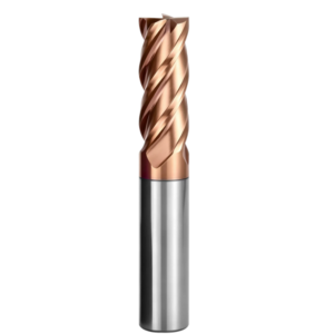
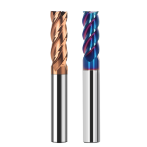
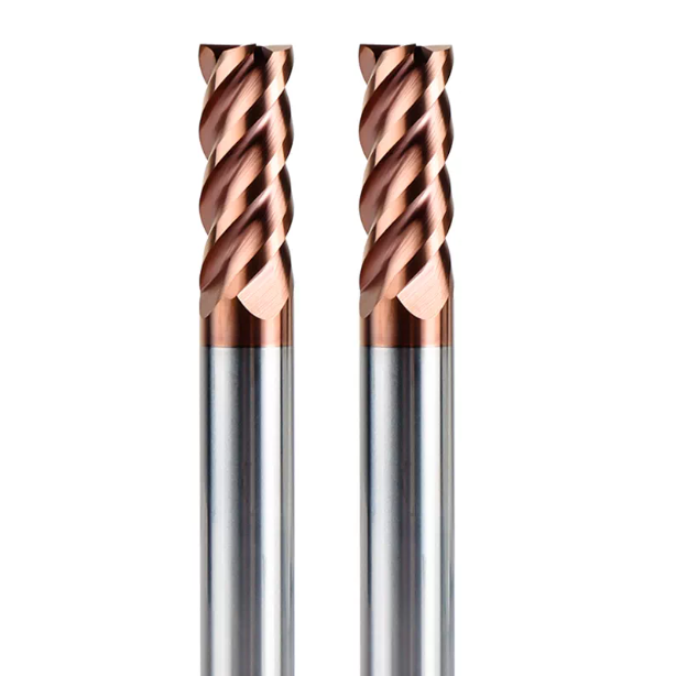
As a cutting tool manufacturer operating our own CNC grinders and running daily cut tests, we know what stable tool life requires. Building a dependable HRC65 hardened steel end mill takes more than a premium 5-axis grinding center. It demands balanced substrate toughness, precise micro-honing, verified coating adhesion, and geometry tuned for extreme heat. If your shop deals with runout variations, edge chipping, or soaring tooling costs, ask yourself: before testing a cutter on hardened steel, how can you truly verify a supplier’s high-hardness machining claims?
Selecting Rods and Substrates: Why Conventional Carbide Struggles with HRC65 End Mills
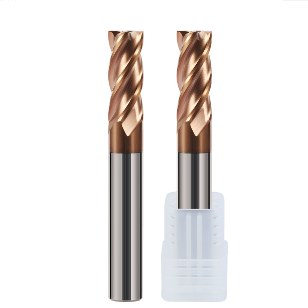
Toolmakers often ask us a simple question: why do tools made from premium European carbide rods fail on hardened mold steel after running fine on pre-hardened stock? The answer lies in the microscopic stress profile of hard milling. Conventional sub-micron substrates handle room-temperature impact well, but extreme shear forces quickly expose internal material flaws. Producing a reliable HRC65 carbide end mill requires shifting focus away from ambient shock resistance toward high-temperature hardness retention and plastic deformation resistance.
In our metallurgical lab, we have sectioned hundreds of broken cutters returned from customer test runs. Most catastrophic fractures originate at microscopic voids along the tungsten carbide and cobalt binder interface. Cutting pre-hardened steels generates moderate friction that forgiving substrates can absorb. In contrast, machining steels above HRC60 drives cutting zone temperatures past 800°C instantly. Without Hot Isostatic Pressing (HIP) and a uniform microstructure, standard carbide deflects, cracks, and shears under load.
Grain Size and Cobalt Content Ratio: The Root Cause of Substrate Fracture in European and American Mold Shops Machining Hardened Steel
Two years ago, we helped a Detroit mold shop debug a high-speed corner-clearing process on DC53 die steel heat-treated to HRC64. The shop reported that their end mills were snapping off cleanly at the neck with zero warning. Our lab analysis identified classic low-cycle fatigue and brittle shear fractures. The customer had selected a carbide grade with 12% cobalt to boost impact resistance. In extreme-hardness milling, excessive cobalt accelerates catastrophic failure instead of preventing it.
Our cutting data confirms that a high-performance end mill for hard steel requires an ultrafine 0.2 μm to 0.4 μm grain size paired with an 8% to 10% cobalt mass fraction. High cobalt softens rapidly under high cutting temperatures, losing its grip on the tungsten carbide matrix and causing plastic deformation. Dropping cobalt below 6% prevents deformation but leaves the cutting edge brittle and prone to chipping. We balance this trade-off by locking in hot hardness and compressive strength while maintaining adequate base toughness.
Coating Adhesion and Thermal Limits: Measured Delamination of AlTiN, AlCrN, and Nano-Micro Composite Coatings in Dry Milling
Dry milling deep pockets in hardened steel often reveals a common failure pattern. After twenty minutes of continuous run time, bright red chips turn dark purple and spark heavily. Surface finishes degrade instantly. Inspecting the rake face under a 3D digital microscope usually reveals extensive coating delamination across the primary wear crater. On a HRC65 hardened steel end mill, lost coating exposes raw carbide to incandescent chips, causing rapid adhesive wear and thermal breakdown within seconds.
In our shop, we benchmarked coating wear on SKD11 blocks hardened to HRC63. Standard single-layer AlTiN oxidizes and breaks down near 800°C. AlCrN coatings introduce chromium, raising oxidation resistance past 1050°C to curb tip adhesion. For deep trochoidal toolpaths, we prefer nanolayered composite coatings like AlTiSiN. The silicon-doped grain structure blocks thermal cracks and sustains critical scratch adhesion loads above 80 N, though it requires precise micro-honing to prevent edge embrittlement during deposition.

Key Micro-Geometric Parameters: Practical Design of Cutting Edges and Flutes for End Mills for Hard Steel
A ground flute profile can look mirror-smooth on an optical comparator yet fail within seconds on hardened die blocks. In our tooling development work, we discarded the assumption that sharper cutting edges yield lower cutting resistance. Designing an end mill for hard steel is not an exercise in macro-level symmetry. It requires engineering a stable micro-geometry that balances wedge angle strength, normal cutting forces, and chip clearance.
When cutting materials past HRC60, a 1-degree angular deviation alters heat dissipation and mechanical stress paths across the tool tip. While troubleshooting a tooling issue for a Swiss moldmaker, we found heavy chip packing during rough milling. Cutting force analysis showed an oversized primary relief angle, leaving a weak wedge angle that collapsed under heavy shear loads. Tool design for hardened steel must prioritize wedge stiffness, utilizing tuned flute geometry to maintain clear chip evacuation channels.
Negative Rake Angle Paired with Large Core Thickness: Engineering Trade-offs Between Impact Resistance and Chip Clearance in Hard Milling
Chips cut from hardened steel do not curl smoothly like low-carbon steel chips; they shear off as discrete, brittle fragments under intense pressure. Because cutting loads concentrate along a narrow contact band, our custom HRC65 end mill designs feature negative radial rake angles from -8° to -15° and an enlarged core diameter of 68% to 72%. This geometry redirects heavy cutting forces back into the rigid center of the tool, utilizing carbide’s superior compressive strength to survive heavy dynamic loads.
Increasing core thickness involves a direct engineering compromise: it reduces usable flute space, making chips prone to recutting inside deep mold cavities. When solving a deep-slotting breakage problem for a French auto supplier, we combined a dual-negative rake chamfer with an asymmetrical parabolic flute trough. This profile restored lateral chip clearance while preserving cross-sectional bending stiffness. If your application demands deep rib milling, high core rigidity works only when feed per tooth is dialed in to avoid flute packing.
Practical Control of Edge Honing (5μm–15μm Micro-radius): Preventing Micro-chipping
Freshly ground cutting edges straight off a 5-axis CNC grinder reveal jagged micro-notches under high magnification. When a new cutter engages hardened steel without controlled edge treatment, these microscopic grinding flaws shatter instantly. On our HRC65 carbide end mill production lines, we hone cutting edges to a precise 8 μm to 12 μm micro-radius. This radius removes damaged surface grains and establishes a consistent, load-bearing cutting edge.
Shop setups often swing between two extremes: leaving edges below 5 μm (causing instant impact chipping) or over-honing beyond 15 μm. An oversized radius exceeds minimum chip thickness, replacing clean shear with rubbing, heavy tool deflection, and workpiece surface burning. We inspect honed edges for a controlled K-factor, shifting the micro-radius toward the rake face in an asymmetric waterfall profile. This profile minimizes initial micro-chipping and provides a stress-free substrate for nano-coating adhesion.

On-Site Workshop Prototyping and Quality Inspection: How to Test End Mills on Hardened Steel
Laboratory test certificates often look flawless with G2.5 balance ratings, sub-3μm runout, and certified coating adhesion. We regularly remind European and American tooling managers that static inspection sheets never predict dynamic cutting vibrations. The only reliable approach for how to test end mills on hardened steel is mounting a heat-treated test block directly onto a rigid CNC machining center. Performance must be verified using real spindle load current, sound signature, and cutting force harmonics.
In our own testing facility, we avoid gentle no-cut dry runs under ideal conditions. Real-world milling involves variable core hardness, uncut stock in tight corners, and sudden programmed direction shifts. Our internal batch verification protocol pushes tools through continuous sidewall friction, alternating shear loads, and thermal spikes. Running cutters close to their physical threshold provides the empirical data we need before clearing tools for volume production.
S136 Hardened Steel End Mill Milling Test: Performance in Deep Cavity Corner Clearing and Side Milling for Mirror-Finish Mold Steel
Machining corrosion-resistant ESR mold steel at HRC52–54 presents serious hurdles for medical and optical tooling shops. The material blends high hardness with abrasive toughness, causing severe built-up edge and rapid work hardening during deep rib side milling. When qualifying each S136 hardened steel end mill, our test routine targets a 3xD overhang depth using air-blast cooling. We evaluate corner-radius integrity and flank wear progression after 40 minutes of uninterrupted corner-clearing passes.
During a joint testing trial with a British mold shop, we evaluated samples with different rake surface finishes. Flank wear alone did not dictate corner-clearing success. Flute friction caused micro-chips to weld inside narrow flutes, degrading surface roughness from Ra 0.2μm to over Ra 0.8μm in minutes. We found that slightly tempering edge sharpness preserves micro-radius strength, while mirror-polishing flute troughs guarantees immediate chip ejection from narrow cavities.
Rigorous On-Site Stress Testing: HRC65 End Mill Chipping Test Under Interrupted Cutting and Sudden Feed Rate Increases
Steady cutting toolpaths often hide microscopic cracks within the carbide substrate. Severe edge failure almost always happens when entering and exiting interrupted cuts. On our automated export lines, every batch must clear the HRC65 end mill chipping test before dispatch. We mill an array of wire-EDM slots and square cross-holes across an HRC65 die block, then run the cutter through these gaps at elevated surface speeds to shock the cutting edge.
Tools that survive without snapping in half do not automatically earn a passing grade. We inspect the cutting edge under a microscope to evaluate crack origins and chipping propagation. Uniform micro-flaking under 5μm after 50 interrupted passes reflects normal fatigue wear. Deep shell-shaped fractures wider than 30μm indicate defective substrate binder distribution or uncontrolled residual grinding stress. We reinforce wedge angle thickness to absorb these sudden shear spikes.
Standardized Wear Recording: Tool Life Comparison for HRC65 End Mills Based on VB = 0.15 mm
Estimating remaining tool life by spindle sound or operator feel creates inconsistent cavity tolerances and wastes usable carbide. Our shop floor enforces ISO-standard optical wear measurement across every HRC65 end mill tool life testing cycle. We set a uniform flank wear land of VB = 0.15mm as the mandatory cutoff point. Machining stops immediately if localized maximum flank wear (VBmax) exceeds 0.20mm.
Flank wear climbs slowly and predictably through a steady baseline period from VB = 0.05mm to 0.12mm. Once wear crosses 0.15mm, cutting friction triggers exponential heat buildup and degrades the coating-substrate bond interface. Continuing beyond this threshold leads to dimensional drift, tool deflection, and spindle overload errors. Swapping cutters at VB = 0.15mm sacrifices marginal run time, but it guarantees zero scrap on lights-out automated mold lines.
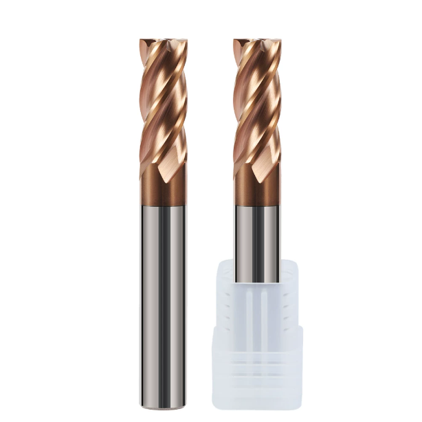
Addressing Specific Conditions for Hardened Steel Mold Machining: Parameter Settings for HRC65 Hardened Steel End Mills in Dry Cutting and Deep Trochoidal Milling
Cutters that excel on a rigid test platform often fail when transferred to deep-pocket mold jobs. Operators frequently lock in median speeds and feeds printed on tool packaging, ignoring structural differences. A high-performance HRC65 hardened steel end mill operates within a narrow speed and feed window. Chip evacuation method, machine tool dynamic rigidity, and instantaneous cutter engagement angle dictate real-world success.
Full-width slotting in hardened steel rapidly accelerates tool failure. Above HRC60, deformation resistance spikes, generating localized shear heat faster than chips can carry it away. Traditional waterline toolpaths double the cutter engagement angle inside pocket corners, exceeding edge shear strength. Linking dynamic toolpaths, chip clearing media, and precise feed-per-tooth limits forms our first defense against catastrophic edge breakdown.
Addressing Thermal Cracking in Air-Cooled, Oil-Mist, and Dry-Cutting Environments: Lessons from a German Client’s 5-Axis Machining Operation
While setting up a 5-axis cell for an automotive moldmaker in southern Germany, we evaluated 1.2379 die steel hardened to HRC64. The shop ran high-pressure flood coolant to eliminate smoke inside the machine enclosure. Within ten minutes of narrow-slot milling, parallel comb-like cracks formed along the cutting edges, leading to severe flaking. Alternating thermal shocks caused this rapid surface fatigue.
Cutting edges reach temperatures near 1,000°C during chip shear, followed by rapid quenching as teeth exit the cut. We switched the operation entirely to cold-air blast and installed an end mill for hard steel engineered for dry milling. Dry machining air blast does not merely chill the tool; it provides dynamic air pressure to blow hot, abrasive chips clear of the cavity, preventing dangerous chip recutting.
Chatter Suppression and Surface Finish Control in Trochoidal Milling (Low Radial Depth, High Cutting Speed)
Roughing deep hardened cavities using deep radial cuts and slow surface speeds destroys solid carbide edges quickly. We instruct customers to adopt high-speed trochoidal strategies, pairing low radial step-over (ae) with full axial depth (ap). Milling deep ribs with a multi-flute HRC65 carbide end mill at 3% to 8% radial engagement and 120–180 m/min cutting speed stabilizes chip thickness within an optimal shear range.
High-speed trochoidal milling depends on machine controller look-ahead and responsive servo acceleration. Without smooth arc cornering, servo lag produces harmonic chatter that ripples across sidewalls and chips tool tips. When tuning programs, we temper feed per tooth to stabilize cutting forces on long-reach tools. Combining variable helix angles with unequal flute spacing breaks up vibration frequencies, delivering smooth, polish-ready sidewall finishes.
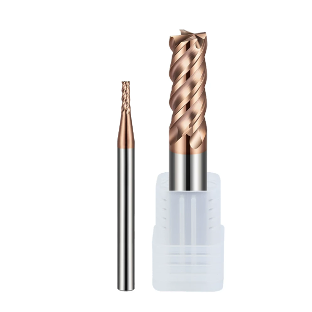
Customization and Batch Delivery Capabilities: Assessing the True Manufacturing Competence of a Custom HRC65 End Mill Factory
Many tooling managers evaluate suppliers based solely on initial cut tests with hand-picked samples. In our production facility, grinding a single prototype with exceptional tool life is easy. The real challenge is holding tight tolerances across a production run of 1,000 pieces. When auditing a vendor for a custom HRC65 end mill, you must look beyond catalog claims. Focus on the thermal compensation stability of their 5-axis CNC grinding centers and their in-process closed-loop tolerance control.
While supporting mold shops across Europe and North America, we have traced most premature tool failures back to batch-level geometric drift. High-hardness milling leaves no room for dimensional variance. A 5 μm deviation in cutting diameter or an uneven neck transition ruins cavity consistency. Without rigid grinding routines and automated in-process probing, high-mix custom manufacturing quickly degrades tool quality and scrap rates.
Grinding Equipment and Runout Control: Consistency of Radial Runout Within 3μm Using Rollomatic and Walter Machines
Touring a tool factory requires looking past the brand names on machine enclosures. On our Rollomatic and Walter 5-axis grinders, our priority is thermal self-compensation over eight continuous grinding hours. For a high-performance HRC65 carbide end mill, total radial runout along the full flute length must remain under 3 μm. If runout drifts to 5 μm, low feeds per tooth instantly turn multi-flute cutting into single-flute overload, causing rapid micro-chipping.
Holding sub-3μm runout in production requires strict environmental and mechanical discipline. We utilize hydraulic expansion chucks, non-contact air-gauging, and synthetic grinding oil chilled within ±0.5°C. Many toll grinders skip wheel dressing cycles to speed up output. We enforce acoustic emission-monitored diamond roller dressing at fixed intervals. This extra step guarantees identical micro-geometry from the first tool to the last.
Relieved Necks and Custom Corner Radii: Meeting Delivery and Tolerance Requirements for Deep-Rib Machining
Standard straight-shank cutters cannot clear deep ribs in high-precision connector and die-casting molds. Tool rooms require long-reach cutters with custom neck reliefs and corner radii. When producing specialized tooling for a Detroit moldmaker running 8xD cavity depths, standard chamfered transitions snapped under deflection. We engineered a smooth, parabolic stepped neck profile for our end mill for hard steel, completely eliminating stress risers under heavy lateral loads.
Forming tiny corner radii under tight delivery schedules requires tight grinding wheel control. Profile deviations above ±3 μm leave visible witness marks on optical mold surfaces during micro-feed finishing. We grind small radii using ultra-fine grit resin-bonded diamond wheels, verifying tangential blend points on 100x optical comparators. While neck reliefs inevitably sacrifice shank rigidity, smooth geometric transitions and strict profile tolerances ensure predictable tool deflection.
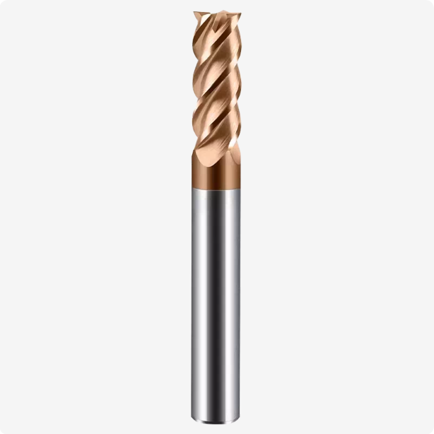
Evaluating Procurement Costs and Value: Assessing HRC65 End Mill Pricing Based on Actual Machining Cycles
Tooling accounts for only 3% to 5% of a typical machine shop’s overhead, yet it dictates the output of a half-million-dollar machining center. In engineering reviews with our B2B partners, we regularly see buyers fixate on purchase prices while ignoring machine downtime and scrap parts. Real HRC65 end mill price comparisons must reflect metal removal volume, cycle times, and spindle utilization. A cheaper cutter that wears out fast costs far more in lost machine hours.
Every design detail—carbide grain density, coating adhesion, edge honing, and flute concentricity—directly affects total machining cost. If you are milling steels past HRC60 and constantly stopping the spindle to swap worn cutters, you should shift focus from purchase price to cost per cubic inch of metal removed. Evaluating tools over full production runs quickly separates cheap cutters from high-efficiency milling tools.
Moving Beyond the Unit Price Trap: True Tool Costs Factoring in Material Removal Rates and Downtime
While benchmarking tool costs for an automotive mold shop, we tested a competitor’s cutter priced 35% lower against our dedicated end mill for hard steel. On HRC64 die blocks, the low-cost tool suffered heavy flank wear and required replacement after 25 minutes. Our optimized tool ran smoothly for 75 minutes under identical cutting speeds and feeds. Factoring in spindle downtime, tool presetting, and operator intervention, the cheaper cutter drove part costs 28% higher.
If you are tracking machining expenses on your floor, calculate cost per cut volume before tool failure at VB = 0.15 mm. Add hourly machine shop rates and tool-change downtime into the equation. A premium cutter that boosts metal removal rates by 20% through superior hot hardness pays for itself immediately. More importantly, consistent tool wear allows lights-out automated shifts without catastrophic tool breakage.
Standards for Batch Inspection and Returns: Quality Acceptance Checklists Used by Major Western B2B Buyers to Evaluate OEM/ODM Carbide End Mill Manufacturers
Experienced tooling engineers rarely accept cutters based on subjective cut tests. They enforce structured quality checklists to verify batch consistency before release. When qualifying a production batch of each HRC65 carbide end mill, our inspection lab checks three critical parameters: full-flute runout under 3 μm, uniform edge honing profiles, and coating scratch adhesion ratings. Variance across any of these points introduces severe chatter and early failure on the spindle.
If you are refining incoming tool inspection procedures, require your suppliers to provide traceable runout data, edge honing charts, and carbide grain size documentation. Every mold cavity, spindle taper, and heat-treated die block behaves differently under load. If your shop is fighting tool deflection, corner chipping, or erratic tool life, we can review your part prints, steel grades, and toolpaths to tailor an end mill geometry to your exact milling setup.