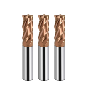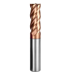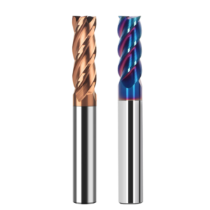
Two months ago, we reviewed a field failure report from a German mold shop. A 5-axis machining center was finish-milling a cold-work die cavity heat-treated to HRC 63–65. Less than ten minutes into cut, a sharp screech echoed from the enclosure, and the spindle load spiked. A brand-new 6mm coated flat tool had suffered severe corner chipping, sending carbide fragments across the finished surface.
The machinist suspected poor coating adhesion or a brittle core. However, inspecting the spindle torque curve and the fracture zone told a different story. This was not a defect in tool production, but a mismatch in tooling geometry. Using a standard carbide end mill for hardened steel applications concentrated cutting shock and radial runout inside a razor-thin shear zone.
Over the past sixteen years of supporting machine shops across North America and Europe, we have seen this failure mode hundreds of times. Once material hardness crosses HRC 60, plastic deformation drops close to zero, turning shear slip into brittle micro-fracturing. Success with HRC65 end mill selection requires balancing substrate cobalt binder, relief angles, differential pitch, and overhang ratios rather than relying on catalog marketing terms.
Milling hardened tool steel leaves zero room for trial and error. A single chipped edge ruins an expensive cutter, burns billable spindle hours, and risks scrapping a die block.
When cutting forces spike and thermal shock threatens tool integrity, have you truly dialed in the right cutter to handle HRC 65 material?
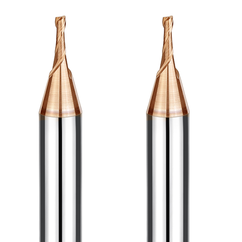
From Substrate to Coating: Material Logic for Hardened Steel End Mill Selection
When troubleshooting broken tools on customer shop floors, we often see programmers pick the hardest tool with the darkest coating. Hard-milling is never a simple contest of matching hardness against hardness. Extreme yield strength directs cutting forces back into the tool tip as high-frequency impact loads. If the tool core lacks sufficient fracture toughness, minor radial chatter causes instant chipping. A sound approach to hardened steel end mill selection balances micro-hardness, fracture toughness, and thermal stability.
On our own production grinding lines, we treat tungsten carbide grain structure, binder volume, coating oxidation limits, and edge honing as an integrated system. Any variation in these parameters gets magnified inside a shear zone running hotter than 800°C. Tool selection requires calculated compromises based on spindle rigidity, cutting speeds, and chip clearing constraints rather than chasing a single peak lab metric.
Selecting the HRC65 End Mill Substrate: Balancing Ultrafine Carbide and Cobalt Content
Machinists often ask us if lower cobalt content always yields better tool life. Lowering the cobalt binder raises room-temperature hardness, but it acts as a double-edged sword. We once ground a custom batch of cutters with 6% cobalt for a Swiss medical moldmaker machining HRC 64 powder metal steel. The cutting edges flaked off entering corner radii because transverse rupture strength fell below the threshold needed for radial shock. That failure reinforced our rules for configuring an HRC65 end mill substrate.
Our production cutting data shows sub-micron grains between 0.2 and 0.4 microns deliver the best balance. Ultrafine tungsten carbide particles form a dense matrix that resists plastic deformation under heavy compressive loads. We hold cobalt binder content between 8% and 10%. This prevents thermal softening at high cutting temps while keeping enough flexural strength to stop micro-chipping under cyclic loads.
High-Temperature Oxidation-Resistant Coatings: Managing Heat in Dry Machining
Cutting HRC 65 steel converts mechanical shearing energy directly into intense heat. Because running dry prevents thermal shock fractures, the tool edge routinely reaches 900°C. Many shops struggle to decide between standard AlTiN and AlCrN coatings. Our milling trials show basic AlTiN breaks down during heavy trochoidal cuts because the aluminum oxide layer degrades under sustained thermal friction, exposing the carbide substrate to wear.
For aggressive dry cuts, coating life depends on the aluminum molar ratio and substrate adhesion strength. High-aluminum AlCrN and silicon-doped AlTiSiN coatings perform far better under continuous dry loads. Adding chromium raises the oxidation onset temperature past 1050°C while reducing tool-chip friction. If high surface speeds concentrate heat in the flutes, switching to a high-aluminum layer controls crater wear and extends HRC65 end mill tool life.
Edge Honing and Rigid Edge Geometry Control for Hardened Steel Cutting Tools
Many operators assume a razor-sharp cutting edge lowers cutting resistance, but that principle fails on hardened dies. An unhoned edge exposed to high-hardness steel crumbles on the first revolution, triggering cascade chipping across the flute. When manufacturing a dedicated hardened steel cutting tool, we subject both roughers and finishers to precise multi-axis brush honing, replacing raw grinding burrs with controlled, load-bearing micro-radii.
The exact hone radius depends on your toolpath strategy. For high-speed finishing cuts with light chip loads, we hold the edge hone between 3 and 5 microns to prevent rubbing and work-hardening. For heavier profiling cuts, we open the hone to 8–12 microns backed by a negative radial rake angle. This microscopic radius trades away a small amount of shearing sharpness to gain massive edge stability under heavy shock loads.
Practical Geometric Configuration: How to Choose HRC65 End Mill Geometries
Many programmers focus solely on carbide grades when ordering tooling. However, once the spindle ramps up, cutting geometry determines whether an edge lasts three minutes or three hours. Hardened steels flex very little under load, creating sharp force spikes every time a flute engages. Dialing in how to choose HRC65 end mill geometry means matching tool core thickness, relief angles, and chip pockets directly to your setup rigidity.
When diagnosing chatter marks or noisy cuts on customer parts, standard soft-steel geometry is almost always the culprit. Materials above HRC 60 generate severe radial loads that deflect slender tools instantly. Every feature—from the corner transition to the rake angle profile—must be reinforced against lateral thrust. Standard deep flutes cut free in soft steel, but they snap under the cutting forces of hardened mold steels.
Types of End Mills in Hardened Steel: Force Distribution Across Geometries
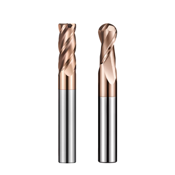
Machinists often try cleaning out square corners using sharp flat-end mills. In our field trials, this causes the highest rate of catastrophic corner failure. Standard flat tools carry fragile 90-degree corners with minimal cross-sectional support. As wrap angles spike in tight corners, heat and mechanical shock concentrate at the tip. When sorting out types of end mills, we advise shops to run bull-nose cutters whenever corner callouts allow.
Corner-radius cutters introduce a smooth blend arc that divides cutting forces into axial and radial vectors. This extra carbide backing protects the tip and leaves a clean floor finish during shallow, high-feed passes. Ball-nose mills handle 3D contouring well, but they feature zero surface speed at their center dead zone. When profiling hardened cavities, tilt the tool 10 to 15 degrees to keep the cut away from that dead center point.
Helix Angles and Flute Design: Variable Pitch and Negative Rakes
A high-pitched squeal from the enclosure warns that your cutting edge is about to fracture. At HRC 65, cutting edges hit the workpiece at violent excitation frequencies. Standard uniform 30-degree flutes build harmonic resonance at fixed intervals, leaving severe chatter waves. We grind tools with unequal indexing and variable helix angles (such as 35°/38°) to scramble tool impact timing and suppress harmonic chatter.
Rake angles also require a different mindset than machining soft metals. For hard milling, we grind a -5° to -15° negative rake combined with narrow clearance lands. Negative rake angles push cutting forces back into the tool body as compressive stress, which carbide handles exceptionally well. Backed by shallow, polished flutes, the beefed-up cutter core resists torsional deflection during continuous cuts.
Selecting Flute Count: Matching Tool Rigidity and Chip Clearing for a Hardened Steel Cutting Tool
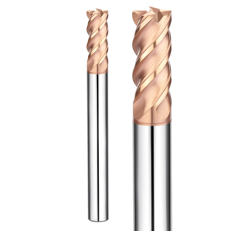
Customers often ask us whether they should run 4-flute, 6-flute, or multi-flute cutters. The choice depends on your toolpath style and chip evacuation limits. While 4-flute designs leave ample chip space, deep flutes compromise the tool’s core diameter. When engineering a dedicated hardened steel cutting tool, we widen the web thickness to 65% or 70% of total tool diameter to prevent bending deflection under load.
If your shop runs high-rigidity machines with dynamic trochoidal toolpaths, 6-flute and 8-flute end mills offer dramatic gains in feed rate and tool life. More flutes let you push higher table feeds at a light chip load per tooth (fz), throwing cutting heat out with thin chips. However, for deep wall finishing or enclosed slotting where chips can pack, stick with a heavy-core 4-flute design to avoid wedging chips into the flutes.
Dimensional Specifications: Matching HRC65 End Mill Diameter to Rigidity Limits
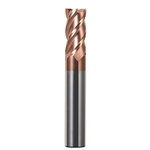
To clear tall cavity walls, operators often choke tools out too far from the holder. Once the spindle accelerates, the tool deflects and emits a high-pitched chatter. Hardened steel offers zero damping cushion; excessive overhang ruins the cut path within seconds. Selecting the proper HRC65 end mill diameter and stickout length comes down to managing deflection formulas and critical vibration limits.
High spindle horsepower cannot make up for poor tool rigidity. Cantilever beam mechanics show that tool deflection scales with the cube of overhang length and drops with the fourth power of tool diameter. Doubling your tool stickout increases deflection eightfold under the exact same radial load. High-hardness milling requires rigid tool setups; always favor the shortest, stoutest tool assembly possible.
Determining HRC65 End Mill Diameter: Managing Deep Cavities and the L/D ≤ 3x Rule
When finishing deep, narrow ribs, engineers often face a tradeoff between tool rigidity and tight corner radii. In our field support, we enforce the 3x length-to-diameter rule. When picking an HRC65 end mill diameter, keep the unsupported overhang below 3x diameter whenever possible. Pushing stickout past 4x or 5x diameter turns crisp shear cutting into rubbing and violent deflection against work-hardened surfaces.
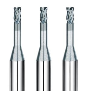
If you must reach deep cavities, avoid straight-shank long-reach tools. Instead, run tapered-neck or undercut tools with larger shank diameters to brace the reach, keeping the fluted cutting length as short as possible. For deep reaches, drop radial depth of cut (ae) to 1%–2% of cutter diameter and run light, fast stepovers. This cuts side pressure and compensates for high L/D ratios without stalling the tool.
Toolholding Systems for Hardened Steel: Runout Control with Shrink-Fit and Hydraulic Chucks
Mounting a premium micro-grain carbide tool in a worn ER collet ruins its performance instantly. In HRC 65 materials, allowable tip runout is close to zero. If total indicator reading (TIR) exceeds 5 microns (0.0002″), multi-flute tools run as single-flute cutters. That overloaded lead tooth chips almost immediately, ruining the remaining flutes. Toolholder balance and runout matter just as much as your programmed feed rates.
Our shop testing confirms two dependable options: shrink-fit and high-rigidity hydraulic chucks. Shrink-fit holders grip 360 degrees around the shank, holding runout under 3 microns at 3x diameter while clearing tight draft angles. Hydraulic holders use internal oil bladders that absorb high-frequency vibration during heavy shoulder profiling. Whichever you run, sweep your tool tip with an indicator before running to keep total runout under 0.003mm.
Real-World Mold Steel Testing: HRC65 End Mill for D2 Steel and High-Hardness Alloys
Testing cutters in a sterile lab differs wildly from milling hardened die blocks on the shop floor. Many toolrooms receive vacuum-heat-treated blocks where surface hardness swings erratically between HRC 62 and 65, locking severe residual stresses inside. When testing an HRC65 end mill for D2 steel, we ignore how fast a tool cuts soft steel. Instead, we measure whether the cutting edge maintains steady, predictable flank wear over hours without catastrophic chipping.
Shop environments carry endless variables. Variations in grain structure across forging lots or residual stock piled in cavity corners can spike cutting forces in milliseconds. Machining high-hardness tool steel requires a balanced system pairing tool toughness with precise load control, machine following error, and proper cooling. Success comes down to keeping mechanical cutting loads well within the tool core’s yield limit.
Milling Hardened D2 Cold-Work Die Steel (HRC 62–65): Beating Carbide Segregation
D2 (1.2379 / Cr12MoV) remains one of the toughest stamping steels we mill. Quenched to HRC 65, its microstructure packs massive, undissolved chromium-rich eutectic carbides that can exceed HRC 70 microhardness. Machinists often report mysterious tool chipping after just a few passes. This failure rarely stems from gross tool overload; rather, the edge micro-fractures when hammering repeatedly into these ultra-hard carbide clusters.
To tame severe carbide segregation, we deploy a defensive D2 steel milling tool strategy. We grind a reinforced micro-chamfer and blend radius onto the tool tip, creating a blunt, impact-proof edge that crushes through carbide clusters instead of flaking off. Furthermore, we throttle surface speed to 45–65 m/min and cap chip loads around 0.015 mm per tooth (fz). High-frequency, light passes ensure exceptional cutting stability and eliminate edge breakage.
Dynamic Milling in Pre-Hardened S136 and H13: Trochoidal Paths and Light Radial Steps
Unlike brittle cold-work steels, S136 stainless mold steel and H13 hot-work die steel present poor thermal conductivity and rapid work hardening. Running conventional straight-line toolpaths into sharp corners spikes the radial engagement angle from 90° past 180°, causing cutting forces to surge violently. When setting up jobs in hardened tool steels, we immediately swap standard offset toolpaths for dynamic trochoidal toolpaths.
Our shop-proven approach replaces deep-radial cuts with high-speed peel milling using large axial depths (ap) and ultra-thin radial stepovers (ae). With 4-flute or 6-flute solid carbide cutters, we lock the radial engagement between 3% and 5% of tool diameter while ramping up table feed. This strategy produces thin, crescent-shaped chips that throw heat away from the cut, holding radial tool deflection close to zero.
Air Blast vs. Minimum Quantity Lubrication (MQL): Why Flood Coolant Fails on HRC65 Cuts
Whenever we walk into a customer shop and spot flood coolant soaking an HRC 65 setup, we halt the spindle immediately. Flooding hot cutters contradicts sound milling physics. Milling is an interrupted cut; tool edges reach 800°C to 900°C in the cut, and cold water-based coolant quenches them the instant they exit. This rapid cycling sparks thermal shock cracks perpendicular to the cutting edge, stripping teeth within minutes.
High-pressure dry cold air is our mandatory baseline for hard milling. Utilizing a cold vortex air gun evacuates glowing chips instantly, stopping damaging chip recutting inside deep mold cavities. For deep ribs requiring mirror sidewall finishes, we switch to Minimum Quantity Lubrication (MQL). A micro-droplet vegetable oil mist creates a high-pressure boundary film, slashing tool friction without introducing thermal shock.
Tool Life vs. Production Cost: Shop-Floor Checklist to Extend HRC65 End Mill Tool Life
True tool life is never just about keeping a spindle spinning as long as possible. If an end mill runs four hours in a cavity but spends the last two hours rubbing dull, it work-hardens the part and adds hours of bench polishing. Extending HRC65 end mill tool life means guiding the tool through uniform, predictable flank wear, retiring it right before edge failure ruins the part.
Tool life reflects every choice made across your machining setup: carbide substrate, negative geometry, rigid toolholding, and dry chip clearing. Rather than cycling through different end mill brands after a chipped tooth, use a standardized diagnostic checklist. Pinpointing wear mechanisms and adjusting feeds lets you extract maximum tool life and surface consistency out of tough setups.
Diagnosing Abnormal Wear Patterns: Crater Wear, Flank Abrasion, and Coating Flaking
Before tossing a dull end mill into the scrap bin, inspect its cutting edges under a 20x shop loupe. Failure modes tell you exactly how your setup is behaving. Massive corner fractures point to entry shock or poor substrate toughness. Uniform flank abrasion confirms clean, predictable tool wear. Deep cratering behind the edge indicates that cutting zone temperatures exceeded the thermal limits of the coating.
If you see coating delamination or heavy cratering, switch to an oxidation-resistant AlCrN or AlTiSiN coating and increase air pressure to clear heat. If you observe tiny, shell-like micro-chipping along the primary relief edge, your honing radius is likely too sharp or your spindle is picking up micro-chatter. Diagnosing the wear signature first ensures your next parameter adjustment solves the root problem.
Load Management and Speeds/Feeds: Securing Consistent HRC65 End Mill Tool Life
Machinists often swing between extremes: either feeding too hard and snapping edges, or babying the tool and rubbing it dull. In hardened steel, feeding too slowly is deadlier than feeding fast. If feed per tooth drops below the edge hone radius, the cutter burns the part surface, induces work-hardening, and grinds away its clearance face. Stable HRC65 end mill tool life requires maintaining a constant chip thickness (hm).
If you are programming 3D finishing passes, shrink your radial stepover (ae) and ramp up programmed table feed to keep the cutter shearing metal cleanly. When clearing corners or deep pockets, use dynamic toolpaths that adjust feeds in real time based on tool engagement angles. Keeping cutting forces flat and consistent prevents load spikes that crack fragile carbide edges.
Pre-Machining Shop Checklist: Spindle Warm-Up, Dynamic Runout, and Tool-Setter Damage
Beyond feeds and speeds, overlooked setup habits ruin hard-milling jobs before the tool ever touches metal. We frequently see operators start aggressive cuts on cold spindles, causing axial depths to drift as bearings expand. Tool-setter probes with heavy spring loads can also micro-fracture sharp carbide tips during touch-off. Dirt inside tool tapers is another culprit that pushes runout past acceptable limits.
If you are battling dimensional drift or immediate corner chipping, implement a strict pre-machining checklist. Warm your spindle thoroughly to operating temperature. Clean holder tapers to guarantee under 0.003mm total indicator runout at the tool tip, and soften tool-setter touch-off routines. If you are struggling with chatter or short tool life on hardened dies, share your part drawings and setups so we can dial in a machining solution for your shop.