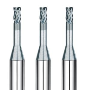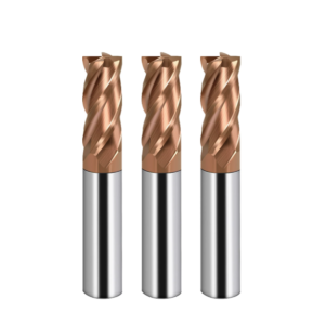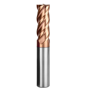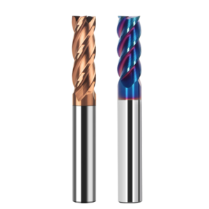
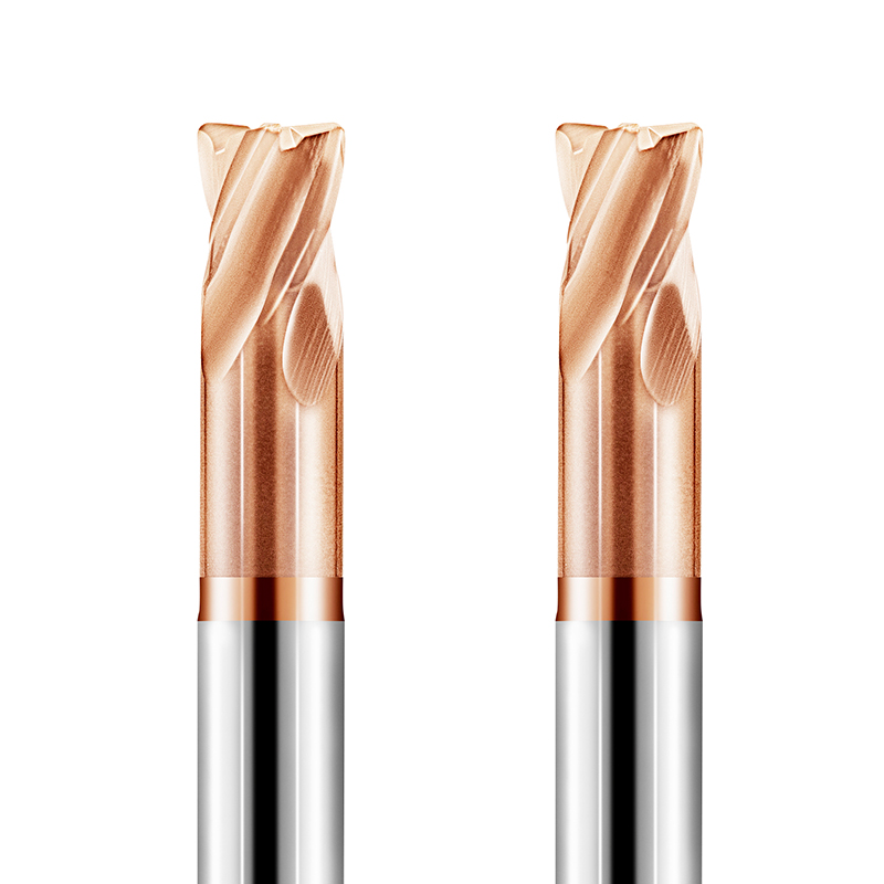
Last month, a long-standing client in Stuttgart, Germany, reached out with an urgent troubleshooting request. They were profiling punches from D2/1.2379 cold-work tool steel heat-treated to HRC 64–66. Their 4-flute end mills—expected to reliably finish two full cycles—were failing within 12 minutes. The cutting edges showed continuous micro-chipping, and the corner radii suffered complete material detachment.
The on-site team instinctively dropped the spindle speed, assuming a slower cut would protect the tool. In our 16 years of cutting tool manufacturing, this remains one of the most common hard-milling errors. When machining ultra-hard steels, running too slow prevents the shear zone from reaching the critical plasticization temperature. The edge plows through cold stock under immense resistance, shifting the wear mechanism from controlled abrasion to severe fatigue spalling.
Dialing in the optimal HRC65 end mill cutting speed is never as simple as copying parameters off the packaging. The real-world window for carbide end mill cutting speed is razor-thin. Factors like carbide substrate grain size, AlTiSiN red-hardness thresholds, spindle runout, and an overhang ratio increase of just 0.5 can cut your working parameters in half. This is why we always evaluate end mill cutting speed for hardened steel alongside chip thinning and thermal evacuation.
When a workpiece is hard enough that a standard file skates off the surface, one question matters: is your cutting speed actually evacuating heat with the chip—or is every single spindle revolution incrementally shattering your tool tip?
Milling Characteristics of Hardened Steel (HRC 62–68) and the Benchmark Window for Carbide End Mill Cutting Speeds
In technical calls with mold and die shops, we often see machinists apply pre-hardened steel (HRC 50) habits to workpieces over HRC 62. Once material crosses HRC 60, fundamental cutting physics change completely. Plastic flow plummets, shear slip turns violent, and chips emerge as discontinuous, high-frequency segments. Cutting resistance and instantaneous heat spike non-linearly.
For cutting tool manufacturers, setting a reliable carbide end mill cutting speed means balancing mechanical impact shock against thermal shear softening. Run too slow, and the edge plows unsoftened base metal, driving severe mechanical fatigue. Run too fast, and interface temperatures blow past 1000°C, stripping coatings and bond layers. You need a verified baseline speed that concentrates thermal energy strictly inside the primary shear zone.
Empirical Cutting Speed Range for HRC65 End Mills (Vc: 45–120 m/min)
Across our testing center and production partner facilities, the practical HRC65 end mill speed benchmark settles between 45 and 120 m/min for steels like 1.2379 (D2) or CPM-10V. This wide range is not an open invitation to tweak feed override knobs at random. Your usable surface footage is locked directly to your radial engagement (Ae) and toolpath kinematics.
In traditional side milling or corner profiling with 15%–25% radial stepover, we hold surface footage to a conservative 45–70 m/min to stop thermal heat buildup at the corners. But in dynamic trochoidal paths with radial engagement limited to 3%–8% Ae, the contact arc drops sharply. Each flute gets ample air cooling time per revolution, letting us push cutting speed to 90–120 m/min for high material removal rates.
Why You Should Not Simply Apply Standard Mold Steel Parameters to CNC Cutting Speed Calculations
In many contract job shops, programmers still pull default mold-steel speed formulas straight out of standard CAM libraries. In our field experience, that remains the number-one cause of catastrophic tool failure on hardened tool steels. Conventional formulas assume predictable bulk ductility. At HRC65, the shear zone narrows to a few microns, while friction coefficients and specific cutting forces spike dramatically.
Plugging standard formulas into your setup yields a heavy chip load paired with an overly conservative surface speed. That directly contradicts hard milling principles. Heavy chip loads generate lateral tool deflection forces that snap carbide flutes. If you do not compensate your cnc cutting speed for chip thinning and effective diameter, the flute rubs rather than cuts. We always calculate effective RPM backward from true maximum chip thickness (Hex).
Comparing the Thermal Degradation Thresholds: Cutting Speed for Milling HRC62 Steel vs. HRC65
Many machinists assume HRC62 and HRC65 are only 3 Rockwell points apart, assuming a 5% speed trim is plenty. Our tool wear metallographic reviews show these two hardness levels sit on completely different sides of a thermal degradation cliff. For cutting speed for milling HRC62 steel, the microstructure still allows mild plastic deformation, keeping flank wear gradual and manageable between 80 and 130 m/min.
At HRC65, alloy carbides sit far denser and more dispersed across the martensitic matrix, generating extreme friction at the flute edge. Running HRC62 speeds on HRC65 stock degrades nanocomposite AlTiSiN coatings within minutes through rapid oxidation and thermal diffusion. Our rule is straightforward: surrender 15%–25% surface footage to stabilize flank wear bands, rather than chasing marginal gains past thermal failure lines.
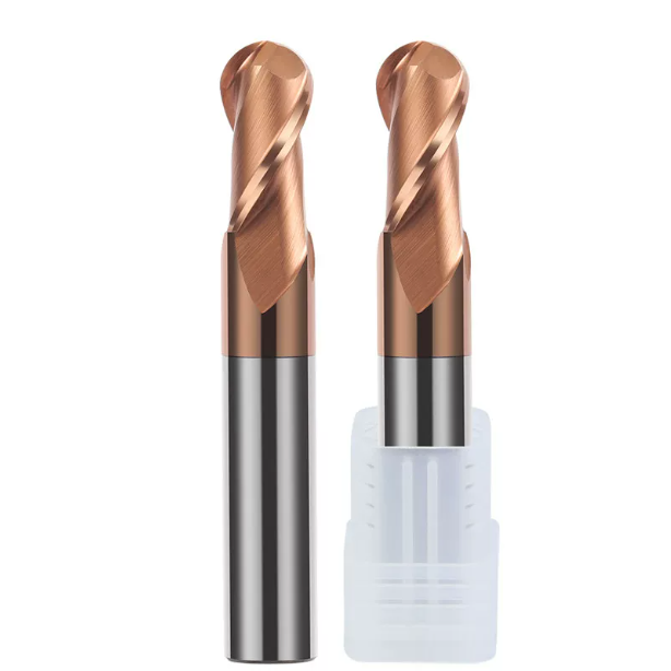
Key Variables Influencing End Mill Cutting Speed for Hardened Steel: Coatings, Substrates, and Overhang Rigidity
When troubleshooting roughing and finishing runs across US and European toolrooms, we constantly see a classic mistake. If a cutter chips at recommended RPM, operators instinctively assume surface speed is too high and pull back the spindle override. Surface speed never operates in a vacuum. Its efficiency is governed entirely by the dynamic rigidity of your toolholder-workpiece system.
In tool manufacturing, we verify that the true ceiling for end mill cutting speed for hardened steel depends on hidden structural variables. Ultra-hard steels exert severe reactive radial forces on the cutting edge. If the substrate lacks shock resistance or the coating delaminates under thermal stress, surface speed becomes irrelevant. You must balance substrate chemistry against overall setup damping.
CNC Milling Cutting Tools for Ultra-High Hardness: Substrate Grain Size and AlTiSiN Thermal Stability
Cutting HRC 62–68 steel destroys general-purpose carbide. For high-performance cnc milling cutting tools, we compress the tungsten carbide grain size to 0.2–0.4 microns and hold cobalt content between 8% and 10%. This is an intentional engineering compromise. We sacrifice bulk ductility to hit 93–94 HRA hardness, stopping the cutting edge from deforming under extreme load.
During dry-cutting tests, contact zone temperatures routinely hover between 900°C and 1050°C. Standard TiAlN coatings oxidize and peel above 800°C, stripping away your edge protection. Our high-silicon AlTiSiN nanocomposite coating forms an amorphous, passivating SiO₂ thermal barrier that resists oxidation past 1150°C. That nano-barrier gives you the heat resistance needed to sustain higher line speeds.
The Impact of Overhang (L/D Ratio) and Radial Runout on HRC65 Milling Cutter Speed Limits
Ask us the number-one reason machinists are forced to lower speeds, and the answer is overhang length. In deep cavity molds, operators frequently choke out tools at 4D to 5D overhang to clear walls, then wonder why the tool chatters. Deflection increases with the cube of overhang length. At micron-level chip loads, that flex creates violent high-frequency vibration.
This chatter destroys an HRC65 milling cutter. Once your overhang exceeds 4D, you must reduce surface speed by 20% to 35% compared to a 3D setup. Total indicated runout (TIR) at the tool tip must stay strictly under 0.003 mm. If runout climbs past 0.005 mm, one tooth absorbs the entire radial shock and micro-cracks. For deep reaches, switch to a necked tool with a reinforced taper.
Logic for Adjusting Cutting Speed for Milling Based on Chip Clearance and Flute Count (4-Flute vs. 6-Flute)
Choosing between 4 and 6 flutes comes down to balancing core strength against chip pocket volume. Many machinists assume thin chips justify 6-flute or 8-flute tools to maximize table feed. While extra flutes increase core rigidity, they reduce chip clearance. In confined cuts, glowing, fractured chips can pack into narrow flutes and weld to the cutter body.
We recommend a tiered adjustment for your cutting speed for milling. For roughing or heavier radial cuts (Ae above 15%), run a 4-flute end mill. The open flutes allow high-pressure cold air to clear chips instantly, preventing recutting. Reserve 6-flute cutters for light sidewall finishing (Ae below 3%). In that setup, you can safely raise surface speed and run high-frequency micro-shearing for a mirror finish.
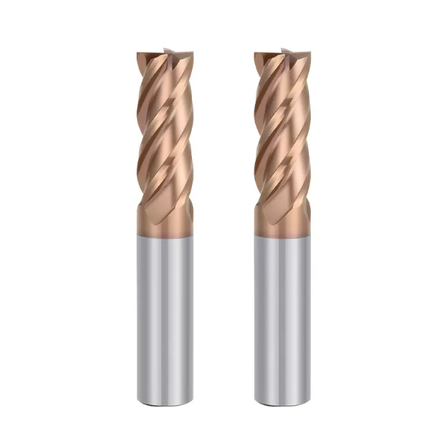
Carbide End Mill Feeds and Speeds for High-Frequency Milling in Modern Mold Shops
When auditing mold-making facilities, we see two extremes. Traditional shops run overly conservative feeds out of fear of tool breakage, while advanced toolrooms run high-frequency micro-milling for exceptional surface finishes. Regardless of your machine controller, surface speed and feed rate must remain tightly coupled.
Dialing in carbide end mill feeds and speeds depends on maintaining a constant dynamic chip thickness (Hex). If feed per tooth drops below the hone radius, the edge stops shearing and begins plowing. This work-hardens the part and burns the flank face. Push feed too hard, and excessive radial pressure snaps the edge. You must coordinate speed, feed, and stepover dynamically.
Optimizing Ae and Ap Ratios to Maximize HRC65 End Mill Cutting Speed in Trochoidal Toolpaths
In deep pocket roughing, dynamic trochoidal paths have largely replaced traditional Z-level hogging. We safely push our HRC65 end mill cutting speed up to 100–120 m/min by strictly limiting radial engagement. We set radial stepover (Ae) to 3%–6% of tool diameter while running axial depth (Ap) at 1.5 to 2 times cutter diameter to utilize the full flute length.
This geometry keeps the tooth engaged for only 10%–15% of each revolution, leaving the remaining 85% open to air cooling. Cutting heat evacuates cleanly without migrating into the tool core. Because Ae is small, chip thinning occurs. You must apply feed compensation, boosting programmed Fz by 2x to 3x so the tooth shears cleanly rather than rubbing.
Balancing Hardened Steel Milling Speed and Feed per Tooth (Fz) to Prevent Corner Chipping
Cutting dynamics collapse when an end mill transitions from straight walls into sharp internal radii. Operators frequently hold a smooth profile cut, only to hear a loud pop as the cutter hits an inside corner. Tool engagement angles spike instantly, multiplying cutting forces and snapping fragile corner radii. Never run straight-line feed rates through an internal pocket radius.
Our field-tested rule protects your hardened steel milling speed: maintain high surface speed and light chip loads (0.03–0.06 mm/tooth) along flat walls. As the path nears a corner, program CAM look-ahead routines to decelerate feed by 40%–60% and drop spindle speed by 10%. Use peeling passes to clear corner stock progressively rather than ramming the full radius in one hit.
3D Mold Contouring: Calculating Cutting Speed for Milling Based on Effective Diameter and Path Smoothing
Ball-nose finishing on 3D contours presents a deceptive geometric trap. Machinists program surface speed using nominal tool diameter, then struggle with rough finishes and rapid center wear. The issue is geometry: calculate your cutting speed for milling using effective cutting diameter (Deff) at actual cut depth, never nominal tool diameter (Dc).
At shallow axial depths (Ap of 0.05–0.1 mm), effective cutting diameter shrinks to a fraction of nominal size. The cutting edge near center zero barely moves, dragging and smearing across the mold steel. Compensate by bumping spindle RPM by 30% to 50% alongside high-speed look-ahead smoothing. If spindle RPM maxes out, tilt the tool 15 degrees on a 5-axis mill to take the dead center off the cut.
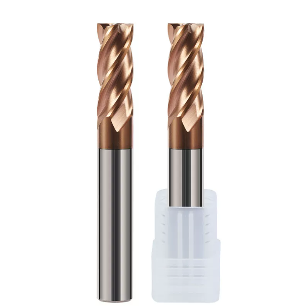
On-Site Troubleshooting: Diagnosing Tool Failure in CNC Milling of Hardened Steel
When answering technical calls from European and American machine shops, we often see operators blame tool quality and swap cutters prematurely. In our experience, every worn cutter pulled from the spindle serves as an operational data recorder. Hard milling allows virtually zero margin for error. Small parameter imbalances leave distinct mechanical and thermal signatures on your cutting edges.
Effective troubleshooting requires reverse-engineering these specific wear patterns. For high-performance end mills for hardened steel cnc, catastrophic failure rarely stems from a single variable. It results from cyclical mechanical loads and thermal shock. Inspect the flank face under a 20x shop microscope before cleaning the tool to separate thermal breakdown from mechanical impact.
Early-Stage Thermal Cracking and Micro-Chipping: Determining Whether CNC Cutting Speed Is Too High or Feed Rate Is Too Low
Under magnification, parallel comb-like cracks running perpendicular to the cutting edge indicate thermal fatigue. When operators push cnc cutting speed beyond the thermal ceiling of the coating, rapid heating and cooling cycles create violent thermal stress. Once this cyclic expansion exceeds the fracture toughness of the carbide matrix, micro-cracks propagate into the substrate and cause edge flaking.
However, thermal cracking can also stem from an insufficient chip load. If feed per tooth is too light, the edge rubs against work-hardened material rather than shearing clean chips, concentrating heat at the tool tip. Check chip color: if chips are deep blue or purple with comb fractures, drop line speed by 15%–20%. If chips are powdery or pale, increase feed to evacuate heat.
Built-up Edge (BUE) and Accelerated Wear: Addressing the Lack of Shear-Induced Softening
Machining HRC 65 tool steel occasionally produces built-up edge or heavy crater wear, which catches many engineers off guard. In our spindle trials, this occurs when the actual hardened steel milling speed sits below the plasticization window. The shear zone never reaches the 600°C–800°C required for localized thermal softening, forcing the cutter to plow through unyielding stock.
This low-temperature plowing destroys edge hones and cold-welds micro-particles to the cutting edge. When these deposits shear off, they pull carbide grains with them, accelerating flank wear. Rather than dropping RPM—which deepens the plowing cycle—increase cutting speed by 10%–15% if setup rigidity allows. Thermal softening will engage, changing the cut from a dull grind to a clean hum.
Practical Validation of Cooling Media: Why Dry Machining with a Vortex Cold Air Gun Outperforms Flood Coolant
Flooding an HRC 65 cut with water-soluble coolant when seeing smoke is a fast way to destroy carbide. Rotating flutes cycle between 1,000°C in the cut and room temperature in the coolant stream within milliseconds. This extreme thermal cycling causes severe thermal shock, leading to rapid coating delamination and micro-fracturing along grain boundaries.
When establishing your baseline cutting speed for milling, run dry with a vortex cold air gun. Chilled compressed air (-5°C to 5°C) does not cool the cutter body; it provides kinetic force to clear chips and prevent recutting. In deep cavities where evacuation stalls, minimum quantity lubrication (MQL) with vegetable oil is viable, but high-pressure flood coolant does far more harm than good.