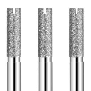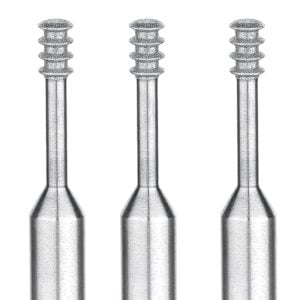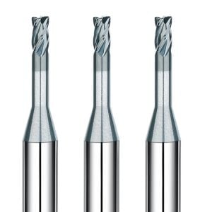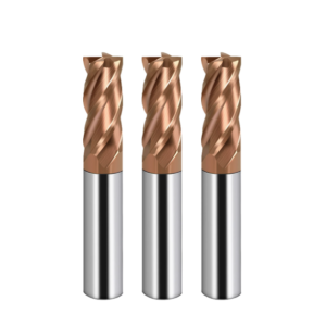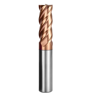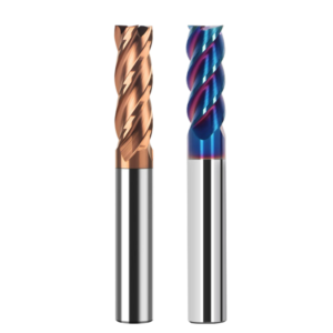
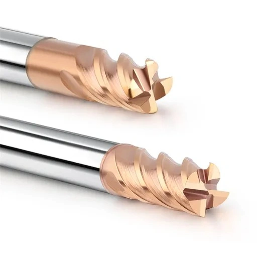
Last month, a shop supervisor at a stamping die facility in Stuttgart sent us high-resolution photos and spindle-load logs of a wrecked setup. They were cutting an SKD11 tool steel insert hardened to HRC 62–65 on a DMG MORI vertical machining center. For roughing and semi-finishing, they selected a 10 mm 4-flute solid carbide end mill engineered for high-hardness materials.
Relying on old shop habits, the team assumed that harder steel demanded a “crawl along” approach. They dialed the spindle back to 1,800 RPM, set the feed per tooth to 0.015 mm, and flooded the cut with water-soluble emulsion. Within two minutes, the cutting edge suffered catastrophic micro-chipping, leaving a burnished, white-layer glazed zone across the workpiece.
Over our 16 years of tooling manufacturing and on-site support across Europe and North America, we see this breakdown almost monthly. Programmers who fly through pre-hardened steels (P20 or H13 at HRC 38–42) hit a wall when raw material hardness climbs past HRC 60. At this threshold, steel loses nearly all plastic deformation capability, turning shear loads into brutal shock waves focused entirely at the cutting edge.
When the tool moves too slowly, the cutting interface never generates the critical thermal energy needed to soften the shear plane. Conversely, setting an ultra-conservative feed per tooth forces the edge below its hone radius, generating friction rather than true chip shearing. What exact HRC65 end mill cutting speeds and feeds allow advanced nanocomposite coatings to survive, while keeping tooth loads safely between rubbing and edge fracture?
Why Conventional Calculation Formulas Fail Completely on HRC65 Hardened Steel
We often see shop engineers pull standard textbook formulas or general catalog charts to calculate feed rates on quenched dies. Many machinists assume cutting speed scales down predictably as hardness goes up, treating a 65 HRC workpiece just like a tougher piece of 4140. In reality, once steel exceeds HRC 60, plastic deformation drops near zero, and the shear zone switches into periodic, brittle fragmentation that invalidates traditional speed-and-feed formulas.
Trying to calculate cutting speeds and feeds for HRC65 hardened steel using end mills with legacy formulas creates an immediate mismatch between thermal stress and mechanical cutting resistance. Hard milling is never about bulldozing material out of the cut. Instead, success demands establishing a tight thermo-mechanical balance right at the micron-scale contact zone of the tool tip.
From Conventional Cutting to “Hot-Hardness Shearing”: Cutting Speed vs. Tool-Tip Temperature
When cutting cold-work steels like D2, SKD11, or DC53 at HRC 65, operators routinely drop spindle speeds to “protect” the cutter. However, our thermal-imaging diagnostics confirm that linear cutting speed ($V_c$) and cutting temperature do not share a linear curve in hardened steel. Modern micro-grain carbide substrates coated with AlTiSiN require a localized, controlled temperature window of 700°C to 850°C to activate the silicon-rich protective oxide barrier.
When running at an optimal HRC65 end mill cutting speed, instantaneous shear heat softens a microscopic layer of the steel directly ahead of the cut. Chips peel off cleanly with a consistent dark-purple or blue color, proving the heat is evacuating with the chip. If you drop the speed below 60 m/min, the steel stays cold and rigid, forcing the tool to mechanically tear the material until the coating chips away.
The “Dead Zone” for Feed per Tooth: Excessive Friction vs Catastrophic Chipping
Chip load (fz) in quenched steel presents the narrowest operating window in CNC milling. Every carbide cutter for hardened steel features a protective edge hone, typically prepared with a 3–8 μm radial hone or micro-chamfer. If your chip thickness drops below this hone radius, the edge stops shearing and begins burnishing the workpiece through high-pressure friction.
This rubbing generates severe cold work-hardening and white-layer formation while scouring the tool flank within minutes. Conversely, pushing chip load past the rupture strength of the sub-micron carbide grain boundaries causes immediate micro-flaking. Establishing an effective HRC65 end mill feed rate means maintaining a strict 0.010–0.035 mm/tooth window, relying on path smoothing rather than arbitrary feed overrides.
Dynamic Rigidity: Spindle Disparities Under Extreme Radial Cutting Forces
Many programmers blame the cutting tool for chatter without inspecting the taper connection. Milling HRC65 material generates massive, high-frequency radial pushback against the spindle face. In our head-to-head field tests on hardened SKD11 blocks, identical cutters running the same stickout on standard BT40 tapers delivered less than half the tool life achieved on dual-contact HSK-A63 spindles.
Standard BT40 holders rely purely on taper friction and allow microscopic elastic movement under heavy side loads and centrifugal expansion. Hardened steel offers zero margin for deflection; dynamic runout exceeding 3 μm overloads individual flutes and triggers tool breakage. When establishing your carbide end mill speeds feeds, you must evaluate the entire system—spindle contact, shrink-fit holder balance, and an overhang ratio held strictly within 3D.
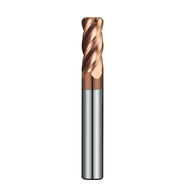
Practical Hardened Steel End Mill Speeds and Feeds for Roughing and Semi-Finishing
Clients often ask if high metal removal rates are possible when roughing HRC65 tool steels. Our answer is yes, but not by taking heavy, low-RPM cuts like you would on mild carbon steel. Trying to take deep radial bites on a 65 HRC workpiece creates extreme thermal shocks that fracture carbide tips within seconds, regardless of spindle torque.
In our field applications, semi-finishing acts as a thermal and mechanical buffer after roughing. By using high spindle speeds with light depths of cut, you bring remaining stock down to a uniform 0.05–0.10 mm envelope. This protects expensive finishing cutters and keeps cutting temperatures in the workpiece from forming micro-cracks before final sizing.
Recommended Corner Radius End Mill Speeds and Feeds for Hardened Steel
Never use sharp 90-degree square cutters for roughing or clearing hardened cavities. On HRC65 steel, a sharp edge acts as a severe stress concentrator; even 0.01 mm of dynamic runout breaks the corner instantly. Switching to a bull-nose corner radius divides the cutting load into axial and radial force vectors, giving the cutting edge far higher impact toughness.
When dialing in corner radius end mill speeds and feeds for hardened steel, keep your axial depth (ap) to 10%–20% of the corner radius. For a D10R1.0 cutter, run ap at 0.15–0.20 mm and radial engagement (ae) at 0.20–0.40 mm with a feed of 0.03–0.05 mm/tooth. Pair this with a 0.6 MPa dry air blast to evacuate chips without thermal shocking the tool.
Controlling Solid Carbide End Mill Cutting Speed for HRC65
Selecting line speed for micro-grain carbide (0.2–0.4 μm grain size) depends directly on machine rigidity. Machinists often run HRC65 cold-work dies at 40 m/min or lower out of caution. However, our SEM analysis shows that excessively low line speeds prevent proper thermoplastic shearing. The coating tears away rapidly, causing severe abrasive flank wear.
We run solid carbide end mill cutting speed for HRC65 between 60 and 90 m/min under dry air or minimal quantity lubrication (MQL). On high-rigidity machines with linear scales, you can push toward 100 m/min to trigger hot-shear softening. On older spindles with detectable runout, dial speed back to 65 m/min with a fine feed to stop micro-cracks before they spread.
HRC65 Cutting Speed and Feed Conversion for Trochoidal Milling and Dynamic Toolpaths
Linear toolpaths cause radial engagement angles to spike from 90° to 180° in corners and slots. In HRC65 steel, that sudden load spike breaks tools instantly. We advise programmers to use dynamic trochoidal toolpaths that cap the engagement angle at 15° to 30°. This keeps the cutting edge in the air longer to shed heat between cuts.
When calculating HRC65 cutting speed and feed in trochoidal milling, you must apply radial chip-thinning factors. With radial engagement (ae) set to just 2%–5% of tool diameter, increase programmed feed from 0.02 mm/tooth up to 0.06–0.10 mm/tooth. You can also safely bump line speed to 110 m/min, preventing the flutes from rubbing on pre-hardened skin.
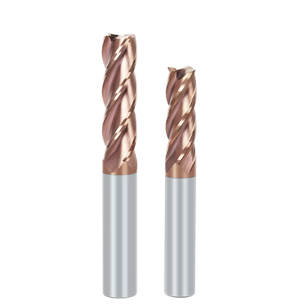
Precise Matching of Spindle HRC65 End Mill RPM & Feed Rate
When troubleshooting cutting noise, we often see operators adjusting machine overrides by ear. While this works on annealed steels, guessing feeds and speeds on HRC65 steel is dangerous. If the feed rate falls out of sync with spindle speed, chip thickness drops below the hone radius, causing immediate micro-chipping or severe thermal rubbing.
To maintain stable cutting dynamics, calculate actual spindle revolutions and axis feed vectors rather than relying on catalog rules of thumb. Our shop rule for HRC65 end mill RPM & feed rate is simple: keep true chip thickness above the edge hone, while keeping spindle load inside the continuous-power curve to prevent servo lag in tight corners.
Calculating HRC65 End Mill RPM Settings by Diameter
Programmers frequently wonder why small micro-mills and large cutters require very different operating strategies in hardened steel. Small tools (D1-D3 mm) are often capped by the machine’s maximum spindle RPM, making it difficult to hit thermal softening temperatures. Conversely, larger tools (D10-D12 mm) reach coating oxidation temperatures very quickly if over-revved.
When establishing HRC65 end mill RPM settings by diameter, never calculate RPM using nominal tool diameter alone. You must calculate RPM against the actual contact diameter derived from your CAM model. If a D6 tool runs a shallow 0.20 mm cut, effective cutting diameter might be under 2.5 mm. You need to increase spindle RPM to hit target line speed.
Calculating Actual HRC65 End Mill Feed Rate & Chip Load Tuning
Table feed (F) is not just tooth count times feed-per-tooth times RPM. In high-speed hard milling with small radial step-overs, chip thinning reduces the actual cut thickness to a fraction of programmed feed. Programming without chip-thinning compensation forces the tool edge to burnish against work-hardened steel rather than cutting underneath it.
When handling on-site HRC65 end mill feed rate & chip load tuning, calculate equivalent chip thickness (h_ex) using CAM compensation or trigonometric formulas. Increase nominal feed per tooth to hit your target chip load. Always cross-check the look-ahead capacity of your machine control to prevent axis hesitation and tool dwell along complex 3D contours.
Machine Tool Dynamics: Rigidity Benchmarks (Hardened Steel End Mill Speeds and Feeds)
CNC machine construction heavily influences cutting performance in 65 HRC tool steel. On purpose-built hard-milling centers (like Makino or Röders), fast servo response and stiff guideways maintain stable tool engagement at high contouring speeds. On general-purpose vertical mills, slower corner deceleration can trigger chatter and spindle resonance if feeds are pushed too high.
The benchmark table below reflects cutting baseline values gathered across European and American mold facilities running hardened steel end mill speeds and feeds:
| Tool Specification | Target Cutting Speed (Vc) | High-Rigidity Centers (Makino / DMG MORI) | Standard VMCs (Haas / Similar) | Cooling Strategy |
| ϕ3 mm R0.2 (4-Flute) | 65–80 m/min | F800–F1200 mm/min (fz≈0.025 mm) | F500–F750 mm/min (fz≈0.016 mm) | Dry cold air / MQL |
| ϕ6 mm R0.5 (4-Flute) | 75–90 m/min | F950–F1400 mm/min (fz≈0.030 mm) | F650–F900 mm/min (fz≈0.020 mm) | Dry air blast (No water) |
| ϕ10 mm R1.0 (4-Flute) | 80–95 m/min | F850–F1300 mm/min (fz≈0.035 mm) | F550–F800 mm/min (fz≈0.022 mm) | High-pressure air / MQL |
Always dial in your speeds and feeds to match spindle torque curves and machine acceleration limits. Balancing machine dynamics with proper chip loads keeps tools cutting reliably and protects machine guideways from heavy vibration.
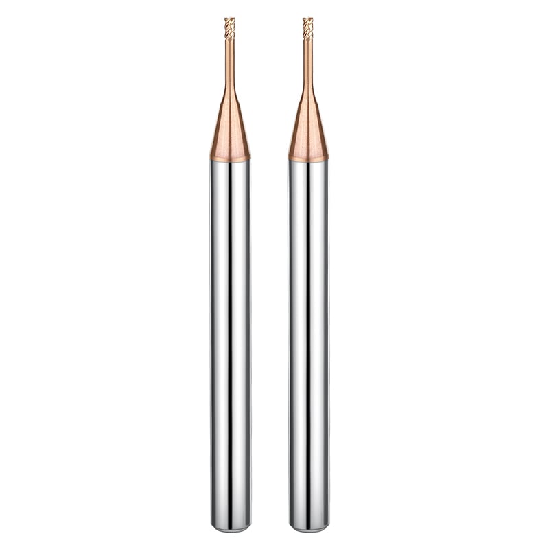
Parameter Optimization HRC65 End Mill Parameters for Finishing and High-Tolerance Machining
In precision injection tooling and micro-stamping dies, shops routinely leave a 0.03 mm grinding allowance for manual bench polishers. Hand-stoning takes hours and frequently rolls critical parting edges or washes out intricate shut-off features. In our contract testing on premium mold centers with spindle runout held under 2 μm, direct hard milling on HRC65 steel reliably hits Ra 0.1–0.2 μm mirror finishes right off the machine.
Finishing hardened steel requires the exact opposite physics of roughing. Cutting resistance drops to secondary importance, while cutter push-off deflection and elastic workpiece recovery dictate true dimensional accuracy. Fine-tuning your HRC65 end mill parameters for finishing demands absolute consistency in cutting forces so micro-honed margins smoothly shave surface peaks without triggering servo stutter or facet stepping.
Corner Clearing and Rest-Milling:HRC65 End Mill Parameter Optimization
Roughing deep pockets with bull-nose tools leaves stepped, non-linear stock in tight internal corners. Operators often drop in a small ball-nose tool and attempt full-depth single-pass corner picking, fracturing the tip instantly. The radial contact angle spikes violently as the flutes engage the corner radius; without programmed multi-pass rest-milling or scallop-height stepping, alternating bending stresses break the cutter.
To keep fragile tool tips alive while holding micron tolerances, limit axial depth (ap) to 0.02–0.05 mm and radial step-over ($a_e$) to 0.03–0.06 mm. When driving HRC65 end mill parameter optimization during corner picking, compensate for lost peripheral line speed by bumping spindle RPM by 10%–15%. This higher engagement frequency overcomes tool deflection and eliminates push-off errors in tight corners.
Chatter Suppression: Hardened Steel End Mill Speeds and Feeds by ±3%–5%
When finishing reflective floors and vertical walls, operators frequently encounter periodic cloudy bands or reflective chatter stripes. Technicians often assume the feed rate is too high or the flutes are dull. In reality, this is almost always regenerative harmonic chatter between the spindle frequency, toolholder reach, and workpiece core resonance.
The fastest way to eliminate chatter on the floor is a controlled micro-step RPM adjustment. When you hear that high-pitched harmonic whine, bump spindle speed by ±3% to 5% at the control panel to break the resonance loop. For long-cycle surface finishing on thin walls, programming spindle speed variation (SSV) permanently prevents regenerative chatter when dialing in hardened steel end mill speeds and feeds.
In-Process Flank Wear Tracking and Offset Management
Flank wear (VB) develops invisibly during high-hardness micro-finishing. Because depth of cut is so shallow, initial edge breakdown barely registers on machine spindle-load monitors. Once flank wear lands exceed 0.05 mm, rubbing friction skyrockets, part dimensions drift undersize, and the cut burns a brittle, re-hardened white layer into the cavity wall.
To safeguard mold tolerances across unattended shifts, we set rigid production rules for running carbide end mill speeds feeds with wear offset. Inspect the cutter tip with an optical tool setter or laser probe every 30 to 45 minutes of cutting time. Cap dynamic wear compensation at 0.003–0.005 mm; once the offset exceeds that threshold, retire the tool to semi-finishing rather than risking an expensive insert.
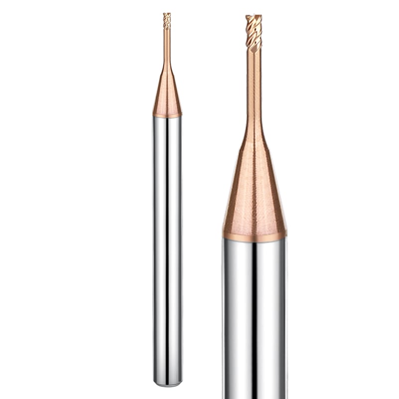
Common On-Site Failure Modes and Corrective Action
Worn cutters tell an exact story under a 50x shop microscope. When operators break a tool, they reflexively slash spindle RPM or cut programmed feed rates in half. This knee-jerk reaction usually makes matters worse: dropping feed rates below the hone radius drops the tool right back into destructive burnishing and friction wear.
Effective HRC65 end mill parameter optimization relies on closed-loop troubleshooting from wear patterns directly back to toolpath dynamics. You must balance thermal-softening activation against mechanical fatigue and coating adhesion. Reading tool-wear morphology lets you diagnose incorrect spindle speeds, feed overloading, or bad coolant strategies within minutes on the shop floor.
Micro-Chipping at the Tool Tip: HRC65 Cutting Speed and Feed Diagnostic Protocols
If cutting edges chip into jagged, shell-like micro-fractures within the first ten minutes of cutting, mechanical impact loads have exceeded the transverse rupture strength of the carbide. This almost always points to corner entries, trochoidal step-ins, or ramping phases where instantaneous chip thickness spiked far beyond planned program limits.
If you are cutting deep pockets and hear sharp clicking sounds at entry, check your lead-in transitions and corner decel settings. Before dropping spindle speed, reduce entry feed rates by 30%–40% on all corner arcs, or drop nominal chip load down to 0.015–0.020 mm/tooth. If you are running flat end mills, swap to a bull-nose corner radius to re-distribute peak cutting forces across an arc while holding optimal HRC65 cutting speed and feed.
Coating Delamination and Accelerated Flank Wear: Air Blast vs. Flood Coolant
Drenching HRC65 tool steel with water-based flood coolant is the single fastest way to destroy cutting edges. Coolant splashing onto spinning flutes creates extreme thermal shock cycles that fracture the bond between the micro-grain substrate and nanocomposite AlTiSiN coatings. Once this protective thermal barrier delaminates, bare carbide rubs directly against 65 HRC steel, destroying flank margins in minutes.
If you are running flood coolant on hardened steel and see chipped coatings or white smoke, turn off the pump immediately. Switch to a 0.5–0.6 MPa dry compressed air blast or minimum quantity lubrication (MQL) to clear chips cleanly without thermal shock. Target a conservative solid carbide end mill cutting speed for HRC65 between 70 and 80 m/min, allowing the tool tip to generate the controlled heat needed to maintain its self-passivating oxide barrier.
Production Scaling: Corner Radius End Mill Speeds and Feeds for Hardened Steel
Parameter strategy shifts completely between low-volume prototype builds and high-volume production cells. When setting up 3 to 5 prototype cavities in an aerospace or die shop, safety is paramount. Run conservative radial step-overs (ae) and baseline cutting speeds to guarantee zero scrapped parts and zero mid-program tool changes.
If you are setting up recurring runs of dozens or hundreds of hardened parts, run an aggressive step-up program. Once initial parts verify on the CMM, bump feed rates and spindle speeds by 5% increments to pinpoint the wear knee for that heat-treat lot. Establishing repeatable corner radius end mill speeds and feeds for hardened steel lets you index cutters predictably between scheduled cycles, balancing edge life against cycle times.
Shop-floor variables often introduce challenges that generic catalog charts simply cannot predict. Variations in machine spindle taper wear, shrink-fit holder balance, tool overhang ratios, and heat-treat hardness spreads (±1–2 HRC) all shift cutting performance. If you are struggling with cavity wall chatter, short tool life, or edge chipping on your HRC65 hardened steel setups, send over your part drawings, machine specs, and current toolpaths so we can optimize your parameters together.