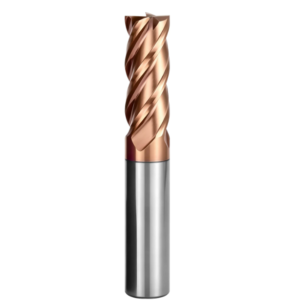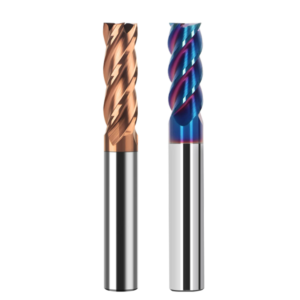

Last month, a precision mold shop in Stuttgart contacted us with an urgent issue. While finish-milling a set of 1.2379 (D2) stamping die inserts hardened to HRC65 on a 5-axis machining center, they hit a wall. After just 18 minutes of spindle time, catastrophic chipping wiped out the tool tip.
The shop engineers initially blamed carbide substrate rigidity or coating thermal resistance. They tested ultra-fine-grain solid carbide cutters from three premium suppliers, yet every tool failed in the exact same spot: the tip corner. Under a high-magnification microscope, the substrate and AlTiN coating adhesion looked intact. The real culprit was the geometric transition zone of the corner radius end mill.
Over a decade of field support across Europe and North America taught us a hard rule: above 60 to 65 HRC, standard tooling margins drop to zero. Many shops tackling HRC65 mold steel machining tweak spindle speeds, feeds, or high-pressure coolant while overlooking micro-geometry. The cutting edge corner radius is the true hub governing load distribution and thermal evacuation paths.
A capable corner radius end mill for hardened steel is never just a square tool with an arc slapped on the corner. The radius dimension, tangential blend to the peripheral edge, edge prep honing, and micro-negative rake angle dictate force resolution. A minor grinding mismatch spikes radial force across a 30-micron contact zone. Local shear temperatures quickly top 900°C, shattering the edge under combined impact and thermal fatigue.
If micro-geometry fails to channel shock loads toward the solid tool core during dynamic milling, expensive nano-coatings and rigid machine setups cannot save the tip. How long can any cutter survive high-hardness steels when force and heat concentrate at a single theoretical point?
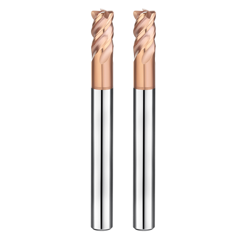
Edge Chipping and Thermal Damage: The Truth Behind Tool Failure—Corner Radius vs Square End Mills in Machining Work-Hardened Mold Steels
Every CNC programmer knows this sound: a brand-new square end mill starts cutting with a crisp, clean tone. Ten minutes later, spindle load indicators begin to flicker. A dull snap follows, leaving a deep gouge across the mold sidewall. In corner radius end mill vs square end mill comparisons, geometry dictates whether you get predictable flank wear or catastrophic chipping.
Pencil-clearing deep, hardened cavities with sharp corners invites premature fracture. Sharp corners lack backing material, slashing the available thermal mass where the end face meets the peripheral flank. Without a corner radius, mechanical stress spikes at that theoretical point. Switching to a corner radius creates a safe machining window, balancing tool life against cavity cleanup limits.
Why Do Sharp-Cornered Square End Mills Inevitably Chip Within 20 Minutes in HRC65 Mold Steel Machining?
Square end mills running HRC65 mold steel machining face extreme material yield limits. At 65 HRC, chips cannot curl via normal plastic deformation. Instead, stock shears off through high-pressure micro-crack propagation. A sharp corner supports near-zero load volume. Initial engagement shock instantly exceeds the carbide’s transverse rupture strength, breaking the corner off immediately.
The thermal trap is equally destructive. Because sharp geometry lacks transition volume, conductive heat transfer stalls. Shear friction heat cannot escape via brittle chips, driving tip temperatures beyond 900°C within microns of the edge. Thermal shock cracks the coating, degrades the cobalt binder phase, and softens the carbide. Once softened, even a micro-impact destroys the unradiused edge.
How Corner Radius Geometry Alters Resultant Cutting Force: Eliminating Stress and Heat Concentration
Introducing an arc shifts the cutting-force vector, which represents the core value of a cutting edge corner radius. A sharp corner directs primary cutting resistance perpendicular to the cutter axis, creating a severe bending moment against the weakest edge. A controlled corner arc distributes this point load along an engagement line, resolving forces into a manageable radial push and an axial component directed up into the spindle.
A radiused corner also opens a 3D conductive highway into the tool body. The larger carbide mass creates a steep temperature gradient, pulling destructive heat away from the cut toward the shank. The arc profile also thins the chip toward the floor, smoothing cut entry and reducing peak impact. This prevents localized heat pooling and ensures steady, predictable flank wear.
Real-World Workshop Case Study: D2/1.2379 Roughing and Rest-Milling with a Carbide Corner Radius End Mill
Last year, a customer struggled with a deep die cavity made of 1.2379 cold-work tool steel at 64–65 HRC. They used a standard 10mm, 4-flute square tool for contouring and pocket clearing. Running at 1,800 RPM and 0.02 mm/tooth, the cutter lost 0.3mm corner chunks every 15 to 18 minutes. Frequent stops stalled production, and wall surfaces were covered in severe chatter marks.
We swapped that setup for a 10mm carbide corner radius end mill featuring an R0.5 corner and negative micro-rake. We increased cutting speed by 15% and stepped up the axial depth of cut. The radiused tip easily absorbed cornering shock, extending stable tool life past 70 minutes with zero chipping. A micro-square tool was kept only for final corner cleanup, tripling overall shop productivity.
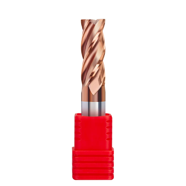
A Micrometric Geometric Game: The Impact of Corner Radius and Transition Tolerances on Tool-Tip Rigidity
European and American mold shops often demand corner radius tolerances within ±0.005 mm. Many machinists think this only prevents parting-line flash in injection molds. In reality, tangential edge blending directly governs tool-tip fatigue life under cyclic loads. A tiny 2-micron step where the corner meets the OD edge acts as a severe stress riser that triggers premature failure under high-speed rotation.
Our shop tests show micro-smoothness matters far more than nominal radius size in ultra-hard milling. Multi-axis CNC grinders with precision-dressed wheels are mandatory to blend the face rake, radius arc, and helical flute seamlessly. A flawless cutting edge corner radius eliminates localized micro-notches, serving as your primary physical defense against fatigue crack propagation in hardened steel.
Micro-Geometry of the Cutting Edge: Edge Preparation and the Tolerance Matching of the Corner Radius
Machinists often chase feed rates while ignoring microscopic edge preparation. Running a raw, razor-sharp edge into 65 HRC steel causes micro-chipping within seconds. Our shop data proves that a cutting edge corner radius demands tightly calibrated edge honing. On R0.5 to R1.0 tools, we hold the honed waterfall chamfer strictly between 8 and 15 microns.
Honing under 5 microns allows hard martensite carbides to shatter fragile grain boundaries on impact. Go past 20 microns, and the edge becomes excessively negative, spiking cutting forces and scorching the part blue. Honing must also scale evenly around the entire corner arc. Any micro-variance between the radius apex and the straight flank causes load spikes that ruin wear predictability.
Designing for Chipping Resistance: Corner Radius Geometry for HRC65-Hardened Steel
Machining steel near the shear limit of tungsten carbide requires abandoning standard positive rake geometry. In our dedicated HRC65 end mill corner radius geometry, we grind the corner rake to -8° to -12°. We pair this with a rigid 6° to 8° primary clearance and an eccentric relief. This profile sacrifices free-cutting ease to build a heavy compressive stress zone behind the cutting edge.
A negative rake converts destructive tensile pull into manageable compressive loads. Meanwhile, secondary clearance geometry prevents severe rubbing against the work’s elastic recovery zone. Quenched tool steel springs back aggressively under load; too little clearance causes extreme frictional heating, while too much weakens substrate support. Balancing these angles within a narrow window keeps the tip stable under heavy cycle loads.
The Side Effects of Improper Corner Radii in Dynamic Milling: Spikes in Radial Force and the Emergence of Chatter Marks
Faced with chipped edges, operators often reflexively switch to a much larger radius. In dynamic toolpaths, this can backfire by spiking radial cutting forces. When a corner radius approaches the axial depth of cut along steep walls, engagement arc length expands. This directs severe lateral push against the workpiece and spindle, triggering chatter marks if toolholding rigidity is marginal.
Conversely, dropping to a tiny corner radius on a 10 mm tool reduces radial deflection but concentrates thermal and mechanical loads on a microscopic point. In our technical reviews, we advise leaving a 0.3 mm finish stock and roughing with an R0.5 or R0.8 carbide corner radius end mill. This compromise delivers high feed rates, avoids part chatter, and preserves cutter life.
Tool Selection and Machining Strategy: Choosing Corner Radius End Mills for Hardened Mold Steels
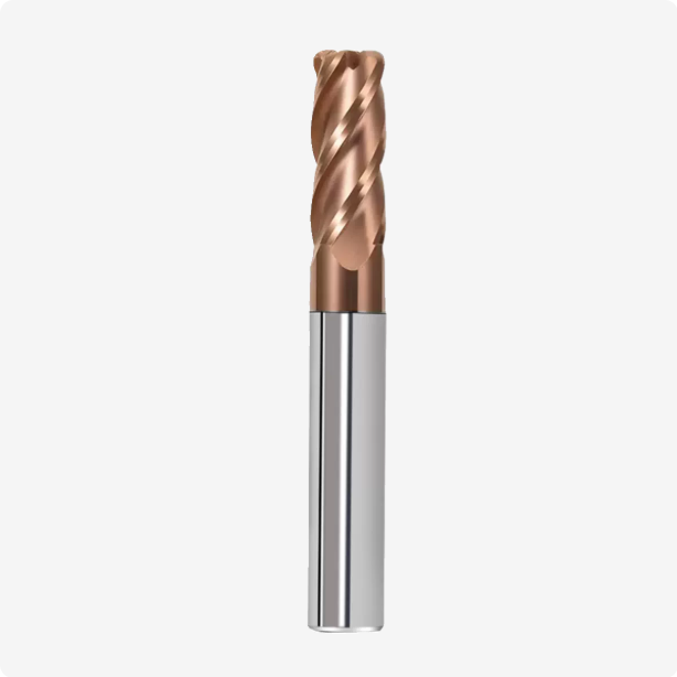
Many programmers treat hardened steel as a slower version of pre-hardened stock, keeping identical cut-depth ratios. In 60 to 65 HRC cavities, improper radial and axial engagements break tools in seconds. Selecting a corner radius end mill for hardened steel requires balancing overall shank bending stiffness against localized edge fatigue limits.
High-rigidity setups with preloaded roller ways and HSK63A spindles handle larger corner radii at elevated cutting speeds and axial loads. In contrast, smaller BT30 tapers or long-reach tools screech under large corner radii. We tailor tool geometry and toolpaths to your spindle dynamics, finding the sweet spot between metal removal rates and tool life.
Corner Radius Selection: Analyzing Force Distribution Across R0.2, R0.5, and R1.0 for Mold Steel Machining
Selecting a corner radius end mill for mold steel involves clear mechanical trade-offs between R0.2, R0.5, and R1.0 geometries. On 10 mm tools, an R0.2 closely mirrors sharp internal part corners, saving downstream sinker EDM time. However, its small radius behaves like point contact, offering only 20% to 30% more impact resistance than a square tool.
Upgrading to an R0.5 radius redirects cutting forces axially, routinely doubling tool life under identical feed rates. This is our default recommendation for roughing hardened cavities. An R1.0 radius withstands moderate interrupted cuts with ease. However, it generates high lateral push that easily deflects thin-walled sections, making dimensional control challenging.
Dynamic Milling vs. High-Feed/Shallow-Cut Strategies: Optimizing Depth and Width of Cut for Deep Cavities and Steep Sidewalls
When programming steep sidewalls, shops must choose between trochoidal passes and high-feed shallow cuts. Using a corner radius milling cutter for dynamic toolpaths (ap of 1.0D to 1.5D, ae of 5% to 8% D) protects bottom corners while distributing heat along flute flanks. This strategy excels in open areas on machines with fast acceleration rates.
In deep pockets beyond 4xD overhangs, deep axial cuts trigger severe tool deflection and chatter. Here, switch to a high-feed strategy: cap axial depth at 20% to 30% of the radius (0.2–0.3 mm for an R1.0 tool) and bump feed per tooth past 0.25 mm. This harnesses chip thinning and channels cut resistance up into the spindle, stopping chatter dead.
Thermal Control and Coating Delamination: Why the Gash Root Radius Must Match the Corner Radius
A tool’s outer corner radius must integrate seamlessly with the gash radius at the flute root. At 65 HRC, glowing chips curl tightly along the rake face under intense heat. Even with a precision-ground corner radius, an abrupt grinding step in the gash traps curling chips. This causes severe chip packing and secondary gouging.
Trapped chips cause immediate thermal spikes at the flute base. Thermal expansion mismatches then cause advanced PVD nanocoatings to flake off the carbide substrate. Once the coating fails, bare tungsten carbide rubs against hardened steel, accelerating rapid crater wear. We grind gash roots and corner transitions as one continuous profile, ensuring chips clear freely with minimal friction.
Custom Corner Radius End Mills as Tailored Solutions for Complex European and American Cavity Molds
Supporting automotive and medical injection mold shops across Europe and North America revealed a clear reality: over 30% of high-hardness jobs fail with catalog cutters. In cavities above 60 HRC, coating wear is rarely the failure point. Standard long-flute tools lack rigidity, and straight shanks collide with steep draft angles. Simply dropping feeds causes chatter, edge chipping, and scrap parts.
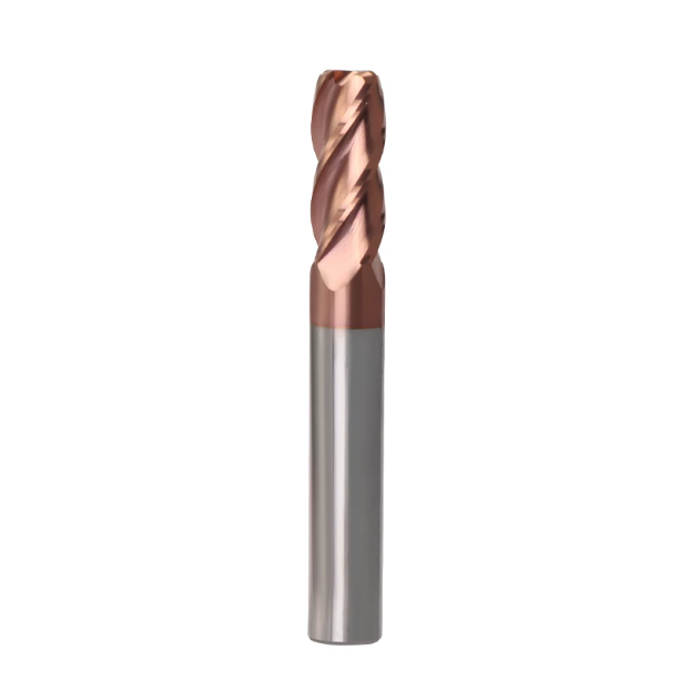
When standard tools hit structural walls, geometric adaptation is the only cost-effective answer. A custom corner radius end mill is not about chasing extreme specs. It re-engineers flute length, neck relief, and blended transitions to keep bending moments inside the core. This targeted tuning delivers dependable cycle times and consistent wall perpendicularity in deep mold cavities.
Custom Corner Radius End Mills for Ultra-Narrow Deep Slots and Thin-Walled Components: Optimizing Clearance Length and Neck Reinforcement
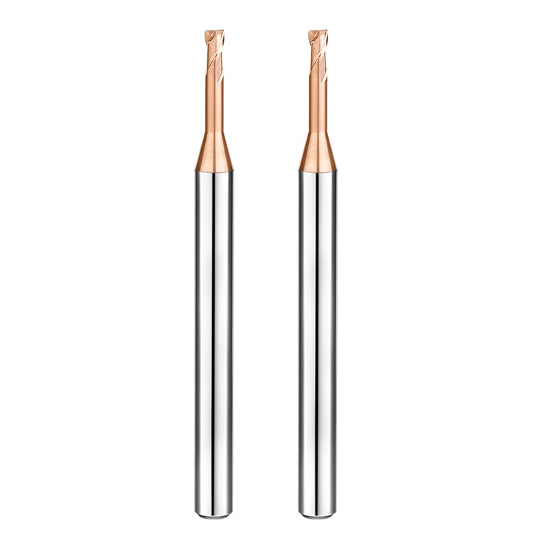
In deep ribs and thin-walled slots, length-to-diameter ratios easily hit 5:1 or 6:1. Tool deflection scales cubically with overhang, making standard flutes chatter instantly. For these setups, we engineer a custom corner radius end mill using a short-flute, tapered-neck profile. We limit cut length to 1.0–1.5xD and grind the neck with a rigid 1° to 3° taper.
This reinforced transition boosts section modulus and shifts natural vibration frequencies away from machine resonance. Blended transition fillets eliminate localized stress points along the neck. At slot floors, small corner radii like R0.15 or R0.25 prevent edge chipping while reducing radial deflection. Even at significant depths, tools maintain floor flatness and wall verticality within 5 microns.
Optimizing Corner Radii and Helix Angles for Custom End Mills Based on Machine Tool Rigidity (e.g., BT30 vs. HSK63A)
Spindle tapers dictate tool geometry constraints. When roughing 65 HRC steels on smaller BT30 tapers, limited pull-stud force and radial stiffness create severe resonance risks. Symmetrical flutes and large radii send harsh vibrations straight into spindle bearings. In these setups, a corner radius end mill must prioritize low radial forces via a compact R0.3 radius and unequal 35°/38° helix flutes.
Switching to dual-contact HSK63A or BBT50 spindles completely alters this dynamic. High clamping rigidity supports stout R0.8 to R1.0 corners paired with steep 42° to 45° helix flutes. These steep flutes eject fine, hardened chips cleanly up the cavity walls. The large corner radius directs heavy loads axially into the spindle, boosting metal removal rates without fretting the taper.
Insights from European and American Shop Floors: A Technical Feedback Loop from Cutting Parameters to Custom Tool Design
Our best technical data comes directly from spindle load spikes, surface finish scans, and microscope wear evaluations on shop floors. On-site tool tuning turns tiny variations in chip thickness and edge breakdown into hard engineering data. This continuous feedback feeds back into CAD models, closing the loop between real-world cuts and grinding programs.
When a die shop reported micro-flaking in deep hot-work cavities, we did not just tell them to lower surface footage. Instead, we redesigned the tool tip’s cutting edge corner radius on their next batch. We replaced the symmetrical hone with a directional waterfall edge prep and adjusted radial relief clearance. Grounding tool geometry in physical shop data is what keeps our custom end mills running reliably for tens of hours.
On-Site Troubleshooting and Doubling Tool Life: Our Practical Approach to Corner Radius End Mill Selection
Tools rarely die from natural abrasive wear; they fail because of mismatched parameters on the machine floor. Precision edge prep, negative rakes, and high-feed shallow passes only work if the NC code respects cutting physics. Our corner radius end mill selection support goes beyond static speed-and-feed charts. We troubleshoot on the floor, balancing spindle stiffness, overhang reach, and corner contact arcs.
If you are cutting 60+ HRC cavities and fighting chipped corners, stop reflexively cranking down the feed dial. Check the thermal dynamics occurring at the tool tip instead. Hard milling leaves zero margin for guesswork across a 30-micron cut zone. Rather than swapping cutter brands blindly, build an objective diagnostic routine based on core hardness and chip formation to stabilize your process.
Three Common Parameter Pitfalls in Western Machine Shops: Excessive Spindle Speeds Combined with Insufficient Feed Rates
Visiting machine shops reveals a common operator habit: fear of breaking tools leads to high RPM and low feed rates. Babying the cutter destroys the edge. Dropping chip load below 0.01 mm per tooth pushes cut thickness under the honed edge radius. Instead of shearing clean metal, the tool rubs and burns burnished flats, generating intense friction that triggers rapid thermal crazing.
Corner moves without feed reduction present another major hazard. When toolpaths turn internal corners, the engagement arc spikes, shock-loading the corner. Flood coolant adds thermal shock, micro-cracking hot carbide under cyclic thermal stress. If you run into premature chipping, switch to dry cold air blast or MQL, and bump the feed so flutes bite cleanly and evacuate heat.
Interpreting Chip Morphology: Fine-Tuning Cutting Speed for HRC65 Corner Radius End Mills Based on Oxidation Color and Curl
Your best process sensor is the chip pile in the enclosure. When dialing in an HRC65 corner radius end mill, skip the console load meter and inspect chips with a 10x pocket loupe. Under balanced thermal conditions, chips form tight “C” curls or small commas. Their color should range from uniform dark blue to greyish-blue, confirming cutting heat exits with the chip.
Bright, silver chips accompanied by fine metallic powder indicate rubbing and burnishing from low surface footage or underfeeding. Conversely, blackened chips, stringers, or heavy sparking warn that temperatures exceed coating thermal thresholds; drop surface footage by 10% to 15% immediately. Reading chip morphology lets you correct parameters before catastrophic flank chipping ruins a workpiece.
Our On-Site Optimization Process for Corner Radius End Mill Selection
Structured cutting trials prevent thousands of dollars in ruined mold blocks. Our technical corner radius end mill selection support relies on four disciplined steps: application geometry audits, dynamic engagement modeling, micro-cut chip analysis, and optical wear inspection. We never start new cutters at redline limits; we begin at 80% baseline speed to evaluate corner entry shock.
If you are planning toolpaths for complex cavities—deciding between an R0.2 rest-mill, an R0.5 rougher, or a custom relieved-neck cutter—share your steel grade, cavity depths, and spindle interface. We will review the physics together. Matching cavity geometry, workpiece microstructure, and edge prep tolerances delivers dependable tool life, even in the hardest steels.