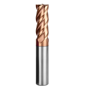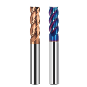
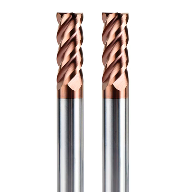
Last month, a toolroom supervisor in Stuttgart sent three worn-out D6 ball nose end mills back to our lab. The workpiece was an SKD11 stamping die hardened to HRC64. The tools showed zero classic flank wear. Instead, the primary edges suffered micro-chipping and thermal fatigue cracks within 15 minutes of cut time. The email read: “Rigidity is solid, and spindle runout is under 2 microns. Why do these cutters break before finishing half a pocket?”
We have seen this scenario play out hundreds of times over the past 16 years. When machining materials above HRC60, traditional carbide end mill cutting parameters do not apply. Cutting-zone temperatures instantly exceed 800°C, and the shear zone shrinks dramatically. Pushing your end mill cutting speed just 10% too fast causes immediate coating oxidation and delamination. Conversely, cutting your feed to “baby” the tool rubs the honed edge against the workpiece, sparking instant work hardening.
In high-hardness milling, tool life hinges entirely on a tight dynamic balance among linear speed (Vc), feed per tooth (fz), and axial/radial depths of cut (ap / ae). Do the end mill speed and feed numbers you run for HRC65 die blocks truly account for holder clamping rigidity, machine dynamics, and the true chip thickness in trochoidal moves?
The Core of Hardened Steel Machining: Carbide End Mill Cutting Parameters and On-Site Tuning
Applying generic catalog charts to ultra-hard steels is the most frequent setup mistake we encounter. Machining alloys at HRC65 subjects cutting flutes to intense mechanical and cyclic thermal shocks simultaneously. You must treat machine spindle dynamics, toolholder overhang, and flute edge prep as one closed loop. Your tuning goal is never raw material removal rates; it is balancing shear heat to soften chips while protecting the carbide core.
Many programmers change speed, feed, and step-over all at once during trials, making root-cause analysis impossible. In our field work, we freeze cutting speed and cut depths first, adjusting only feed per tooth in single steps. We monitor chip color and flank wear progression continuously. If chips turn from deep blue-purple to pale, shiny gray, shear heat is baking the cut zone instead of clearing with the chip. Recalibrate your carbide end mill cutting parameters immediately to avoid thermal failure.
Avoiding the Chipping Zone: End Mill Cutting Speed in the HRC 60–68 Range
Dropping spindle speed linearly when stepping up from HRC50 to HRC65 die steels like D2 or DC53 is a dangerous trap. Permissible surface speed drops non-linearly across this threshold. A micro-grain cutter running 120 m/min at HRC55 must drop sharply to 45–65 m/min at HRC65. Exceeding this boundary pushes cutting-edge temperatures past the thermal limit of the coating in seconds.
A sharp, high-pitched squeal at initial engagement rarely points to excessive feed; it signals excessive surface speed. High speed spikes shear stress and triggers edge micro-chipping. We routinely dial back spindle RPM to keep surface speed conservative, letting the transverse rupture strength of the carbide do the work. Keeping your end mill cutting speed within strict safety limits prevents chipped flutes that can instantly scrap a high-value mold cavity.
Real-World Machine Rigidity: Setting Your End Mill Feed Rate and True Chip Load
Theoretical feed calculations from CAM software are frequently detached from machine realities. We often see operators drop feed rates too low out of caution. However, typical hard-milling edge hones measure between 4 and 8 microns. If your feed per tooth drops below this radius, the flute plows and rubs rather than shears. This friction induces severe localized heat, dulling the tool in minutes.
Target chip load must match your taper size and projection length. On a rigid BT40 dual-contact spindle, we typically start a D6 ball mill at 0.03–0.05 mm/tooth in hardened tool steels. On a BT30 spindle or with an overhang past 4xD, reduce step-over while keeping chip load above the hone threshold. Calibrating your end mill feed rate against tightly curled, uniform chips gives the only dependable proof of stable cutting conditions.
Radial and Axial Depth of Cut: The ap / ae Window for High-Feed and Trochoidal Milling
Full-slotting or heavy radial side-milling in HRC65 steel guarantees sudden tool breakage. Overhauling roughing programs requires strict rebalancing of axial and radial depth ratios. In high-feed milling, we rely on shallow axial cuts combined with heavy chip loads. The radius thins the chip, directing cutting forces upward along the machine spindle axis to minimize deflection.
For deep cavities, ribs, or tight pockets, trochoidal peel milling is the most reliable strategy. Keep your radial step-over (ae) strictly within 5% to 10% of tool diameter while running axial depth (ap) up to 1.0 to 1.5 times diameter. This tiny radial engagement angle keeps in-cut arc time minimal, giving flutes time to cool in the air cut. Dialing in a dynamic depth of cut is what separates fragile setups from predictable, lights-out hard milling.
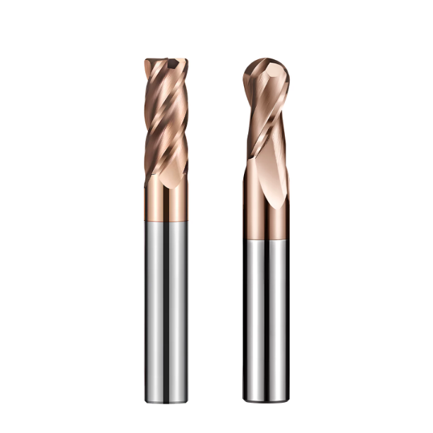
Practical Data Matrix: Hardened Steel Milling Parameters Across Hardness Ranges
Treating all hard metals as one single category is the quickest way to ruin tooling. In reality, the cutting mechanics of HRC58 alloys differ completely from HRC65 high-carbon steels. As Rockwell hardness climbs, metal elongation drops, and shear-zone stress spikes non-linearly. Calculating reliable hardened steel milling parameters requires quantifying plastic deformation, edge temperature spikes, and dynamic spindle stiffness.
Through thousands of field runs, we established a clear rule of thumb. For every 2 to 3 HRC gain, cutting resistance punishes tool flexural strength far harder. The matrix below defines the threshold between roughing and finish passes. Adjust these values to your specific machine rigidity, and always judge stability by chip color rather than theory alone.
Precision Mold Benchmark: HRC65 End Mill Speed for SKD11, D2, and Cr12MoV
Quenched SKD11 and D2 (HRC 62–65) contain dense networks of un-dissolved primary carbides. These hard inclusions make flutes prone to edge micro-fracture under uneven loads. On high-end 5-axis machines, an optimal hrc65 end mill speed for skd11 sits strictly between 50 and 70 m/min. Pushing beyond 75 m/min causes coating delamination from frictional heat, triggering micro-chipping within minutes.
Roughing and finishing demand opposite cutting strategies. When roughing D2, we drop surface speed to 45–55 m/min to support heavier chip loads. For final 0.03 mm finishing, speed can bump up slightly to leverage local thermal softening. If you spot chatter marks or surface discoloration, back off spindle RPM immediately.
Powder Metallurgy Steels: Carbide End Mill Speeds and Feeds for CPM 10V and ASP 23
Vanadium-rich powder steels like CPM 10V and ASP 23 (HRC 63–66) present uniform hardness without carbide segregation. However, their high concentration of abrasive carbides wears down tool flanks far faster than conventional die steels. In client trials, our optimized carbide end mill speeds and feeds rely on conservative surface speeds paired with shallow, high-frequency cuts.
Heat management is the defining challenge with powder metallurgy tooling steels. The dense matrix traps shear heat, transferring thermal energy straight into the cutting edge. We recommend a fine chip load of 0.015–0.035 mm/tooth at 35–50 m/min. Continuous high-pressure air must blast microscopic debris away to stop edge degradation.
H3: Shop-Floor Benchmarks: HRC65 Milling Parameters for Ball, Bull-Nose, and Flat End Mills
Spindle dynamics dictate how these tools perform on the floor. Compact HSK-E tapers offer agile acceleration but modest low-end torque, while BT40 setups offer superior radial stiffness. Our baseline hrc65 milling parameters assume G2.5 balance and runout under 3 microns in thermal shrink holders:
| Tool Geometry & Size | Cutting Speed Vc (m/min) | Chip Load fz (mm/tooth) | Axial Cut ap (mm) | Radial Cut ae (mm) | Recommended Strategy |
| D10 Flat End Mill (4-Flute) | 45 – 55 | 0.04 – 0.06 | 0.20 – 0.40 | 0.50 – 1.00 | Trochoidal roughing, corner cleanup |
| D6 Bull Nose (R0.5 / 4-Flute) | 55 – 68 | 0.03 – 0.05 | 0.12 – 0.25 | 0.30 – 0.60 | High-feed pocketing, semi-finishing |
| D4 Ball Nose (2-Flute) | 65 – 80 (effective) | 0.02 – 0.035 | 0.05 – 0.08 | 0.08 – 0.15 | 3D contouring, shallow finish passes |
Watch your effective cutting diameter carefully when using ball-nose cutters. When contouring flat floors, center-line speed drops to zero, causing flutes to burnish the surface. We recommend tilting the tool 10°–15° in CAM to ensure the true cutting action happens along the outer radius.
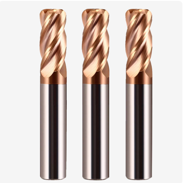
Process Chain Factors Affecting Tool Life: Beyond Balancing End Mill Speed and Feed
When tool life falls short in a hard-milling setup, operators often rush to adjust feed and speed overrides on the CNC control. However, cutting HRC65 steels requires viewing the machine, toolholder, flute micro-geometry, and chip evacuation as an integrated system. A single weak link in this chain leads to sudden tool failure, regardless of how accurate your theoretical feed charts appear.
We remind our manufacturing partners that machining ultra-hard steels requires broad process-chain discipline. Merely adjusting your end mill speed and feed cannot solve root causes like runout, tool deflection, or chip recutting. Stabilizing coating selection, holder balance, and cooling strategy is the only reliable way to achieve consistent tool life across production shifts.
Why Coatings and Micro-Chipping Dictate the Stability of End Mill Parameters
A cutting tool coating is not decorative; on HRC65 steel, it acts as an essential thermal and oxidation barrier. Standard AlTiN coatings break down quickly above 800°C as aluminum migrates outward, accelerating oxidation. Silicon nanocomposite coatings like AlTiCrSiN generate dense, self-healing silicon dioxide and aluminum oxide layers that remain stable past 1100°C.
Even premium coatings fail without proper edge preparation. Unhoned micro-serrations chip immediately upon striking hardened steel, triggering sheet delamination of the coating layer. In our tool grinding operations, we hold edge honing strictly between 4 and 7 microns, followed by micro-polishing. Stable end mill parameters require this uniform edge radius to handle heavy shear loads without generating excessive frictional heat.
The Impact of Toolholders and Runout Control When Machining HRC65 Hardened Steel
A radial runout of 5 microns is acceptable in mild steel, but it causes instant tool failure in HRC65 materials. Because chip load in hardened steel ranges from 0.02 to 0.04 mm/z, a 5-micron runout forces one flute to shoulder double its intended cutting load while the other flutes rub. This uneven shock load shatters carbide cutting edges in seconds.
Comparing toolholding options, shrink-fit holders offer compact profiles and balanced concentricity, consistently holding runout under 3 microns at 3xD overhang. Hydraulic chucks provide oil-damped vibration reduction that excels in light-depth finishing, though prolonged heavy roughing can induce slight deflection. Strict runout control is essential for machining hrc65 hardened steel without unbalancing dynamic cutting forces.
Cooling Media Comparison: Why We Recommend MQL and Cold-Air Blast
Flooding hot, hardened steel with liquid emulsion coolant acts as a destructive thermal test on carbide flutes. Cutting edges spike to hundreds of degrees within milliseconds during engagement, only to be quenched violently upon exiting the cut. This cyclic thermal shock creates micro-cracks that propagate rapidly, ending in catastrophic edge fractures.
In client facilities, we prioritize dry cutting paired with high-pressure cold air or Minimum Quantity Lubrication (MQL). Clean compressed air at 0.6 MPa clears hot, abrasive chips instantly, preventing destructive chip recutting. Introducing an MQL vegetable-oil aerosol creates a thin lubricating barrier along the rake face, lowering friction. Switching away from wet flood coolant to dry air flow protects your hrc65 end mill cutting parameters from thermal shock failure.
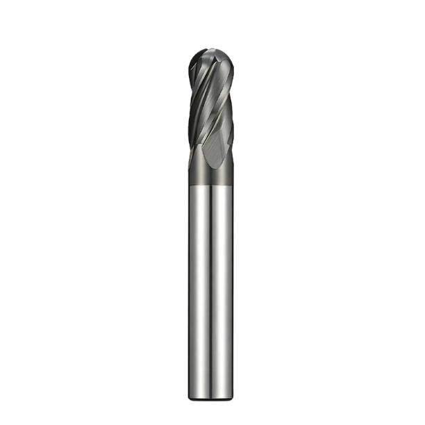
On-Site Troubleshooting and Technical Support: Common Failure Cases for HRC65 End Mills
Blaming poor tool quality is a common reaction when tools break in hardened tool steels. At HRC65, material lattice slip is locked, and fracture toughness drops sharply. Even minor spindle or path vibrations immediately destroy the cutting edge. When arriving on-site, we never just swap cutters; we inspect flank wear bands, crater depth, and grain discoloration under a 50x optical microscope.
Accurate diagnosis requires correlating spindle bearing play, toolholder clamping torque, and corner toolpath smoothing. Over years of field work, we compiled a database of hundreds of hard-milling failure analyses. Through dedicated hrc65 end mill technical support, we help facilities resolve the three most common failure modes found in molds, dies, and wear plates.
Root Causes of Abnormal Flank Wear and Micro-Chipping: Surface Speed vs. Feed Rate
Engineers often struggle to differentiate between thermal failure and mechanical abrasion. At an Italian mold facility, an operator dropped feed rates to 30% out of caution, flattening the cutting edge within twenty minutes. In HRC65 steel, an undersized chip load forces the cutting edge to rub and burnish rather than shear. This rubbing generates extreme heat, causing instantaneous flank softening and mirror-like wear.
Conversely, jagged micro-chipping with dark purple heat tint indicates excessive surface speed. High spindle RPM degrades the coating, while undersized chip loads worsen flank abrasion against the work-hardened layer. We consistently drop cutting speed by 15% and increase feed per tooth above the edge hone radius. Moving from friction to genuine micro-shearing protects your end mill parameters from sudden failure.
Eliminating Corner Chatter and Overcutting: CAM Toolpaths and Dynamic Feeds
Internal corners and tight radii are notorious zones for catastrophic cutter breakage. As a tool enters a 90° inside corner, radial tool engagement jumps abruptly from 20° to over 90°. This spike in cutting force induces high-frequency chatter and deflects the tool shank, creating a work-hardened dead zone.
Dialing down the feed override at the CNC control panel cannot resolve corner deflection. Programmers must introduce trochoidal paths, corner peel loops, and dynamic feed reduction in CAM. We advise programming corner blend radii at least 1.2 times the cutter radius with look-ahead deceleration. Applying adaptive end mill parameters eliminates cutting force spikes, chatter marks, and cavity gouging.
Deep-Cavity Corner Clearing: Rigidity Compensation for Long-Overhang Tools
When cavity depth exceeds 4 to 6 times tool diameter, bending deflection scales cubically with overhang length. At a German electronics mold shop, an operator ran a D6 bull-nose tool at 35 mm projection with standard short-reach feeds. The tool engaged the wall, triggered loud resonance, and snapped at the neck. Long overhangs simply lack the radial rigidity to resist heavy lateral cutting forces.
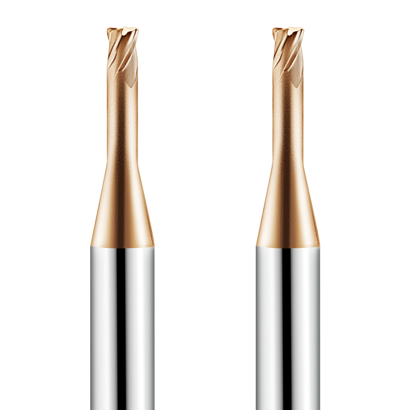
Under high-overhang conditions, you must switch to a relieved, tapered-neck tool body (1°–2° back taper) and run light radial peeling cuts. We drop radial step-over (ae) to 2%–3% of tool diameter while moderately bumping chip load. This strategy directs cutting forces axially up the rigid spindle centerline. Combining deep axial passes with tiny step-overs keeps your hrc65 end mill cutting parameters stable in deep cavities.
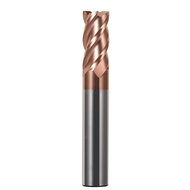
As an HRC65 End Mill Manufacturer: How We Help Machine Shops Reduce Cost Per Part
Tool purchase price is often overemphasized on shop expense sheets. In mass production of HRC65 dies, real costs stem from unscheduled downtime, broken cutters, manual bench polishing, and scrapped cavities. As an experienced cutting tool developer, our goal is matching tool micro-geometry to shop conditions. We convert unpredictable tool chipping into controlled, gradual flank wear.
As a dedicated hrc65 end mill manufacturer, we know no two machine shops share identical cutting environments. Spindle dynamics, shrink-fit runout, air blast delivery, and CAM corner smoothing all place distinct loads on the cutting edge. Rather than shipping generic catalog tools, we partner with your engineering team to audit your process chain. Replacing guesswork with empirical data minimizes your true cost per part.
Customized Edge Preparation and Tailored End Mill Parameters
Hard milling is high-stress micro-shearing where the initial microns of the cutting edge dictate tool life. Off-the-shelf tools with standard hones perform inconsistently across different alloys. High-carbon cold-work die steels require waterfall-type micro-chamfers to survive impact, while powder metallurgy steels need symmetrical hone radii with mirror-polished flutes to prevent rubbing heat.
If you are dealing with premature edge flaking on hard alloys, send us your material grade, hardness data, and gauge length. We use in-house multi-axis CNC grinding and edge-honing centers to tailor hone radii to your spindle capabilities. We then generate validated end mill parameters backed by real wear-rate curves to secure a reliable, productive cutting window.
Establishing Repeatable Hard-Milling Standards: Closed-Loop Process Support
Consistent hard milling cannot depend on individual machine operator intuition; it requires repeatable standard operating procedures. Lowering surface speeds, switching to MQL or dry cold air, holding runout under 3 microns, and programming corner feed drops must be documented. Standardized setups protect your cycle times and tool budgets against shift changes and operator turnover.
If you are replacing EDM with direct hard milling or struggling with erratic tool wear across machining centers, send us your cavity models and worn tool micrographs. Our engineering team provides structured hrc65 end mill technical support from initial test cuts to harmonic vibration checks. Together, we establish robust machining standards tailored to your machines, holders, and setups.