
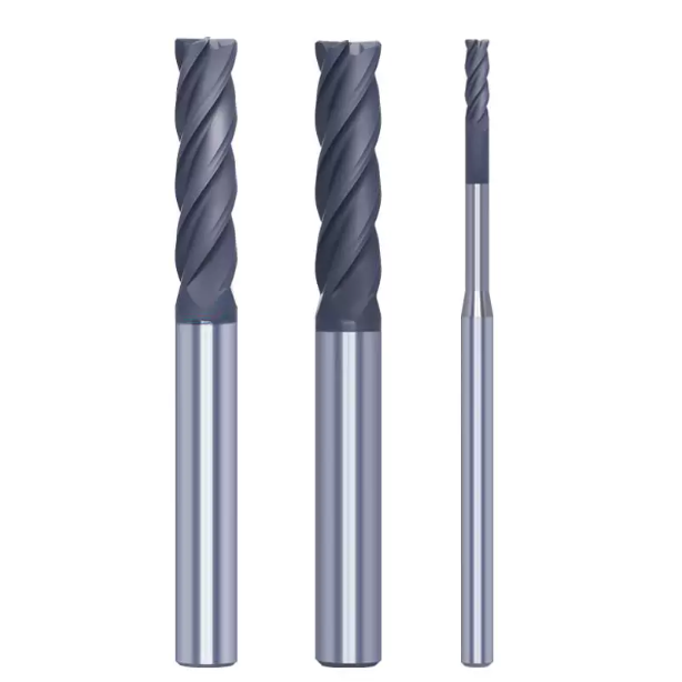
Last month, a German medical device customer sent two scrapped zirconia ceramic sealing rings to our shop. The issue was unmistakable: dense micro-chipping along the precision-milled groove edges, with defects exceeding the 0.05 mm tolerance limit. The customer asked why the edges still cracked like glass upon tool entry and retraction, even after switching to a premium diamond end mill for ceramic and running at 35,000 RPM.
This is a scenario we have resolved hundreds of times over the past 16 years while engineering cutting solutions for European and American workshops. Machining hard, brittle ceramics is not metal cutting; it is a delicate balance between brittle fracture and micro-plastic removal. Relying solely on expensive tooling will not stop chipping. Success requires an integrated approach covering edge micro-honing, rigid tool holders, controlled trochoidal paths, and application-specific geometry.
- Micro-Scale Edge Prep and Adhesion: Flawed cobalt-leaching causes the micro-diamond layer to peel under impact loads, spiking cutting force and shattering workpiece edges.
- Geometry-Driven Stress Relief: Switching to round nose end mills distributes point loads and significantly lowers shear stress at corners and profiles.
- Dynamic Load and Runout Control: Trochoidal toolpaths paired with light feed rates and spindle dynamic runout below 3 µm eliminate shock loads.
- Batch Consistency from Suppliers: Sourcing a reliable china diamond coated carbide end mill requires auditing edge radius uniformity alongside coating hardness.
If you are struggling with high scrap rates or soaring replacement costs, ask yourself: is your diamond tool truly engaging the ceramic the way its geometry was designed to?

Why Is Edge Chipping Inevitable in Ceramic Machining? A Look at Cutting Mechanisms and Tool Loads
On the shop floor, we often see engineers blame bad raw materials or dull tools whenever ceramic edges fracture. However, examining the cut cross-section under a 200x microscope reveals the real culprit. Metal machining relies on continuous shear deformation to form chips, whereas sintered ceramics possess almost zero room-temperature ductility. Material removal happens primarily through high-frequency, localized brittle fracture, transmitting destructive shocks into the substrate if mismanaged.
When a diamond end mill for ceramic enters materials like Al2O3 or SiC, massive contact stresses concentrate along the cutting edge. Without sufficient lateral support or consistent chip loads, micro-cracks propagate along grain boundaries and tear chunks from the finished boundary. To eliminate edge damage, you must mechanically keep cutting forces below the fracture toughness limit rather than hoping the workpiece can withstand the impact.
Micro-Crack Propagation in Hard-Brittle Materials: Controlling the Transition Point
When optimizing parameters for zirconia components, we always focus on ductile-regime machining. Under extremely small depths of cut, intense hydrostatic pressure suppresses crack propagation, allowing ceramics to shear smoothly like metals. However, maintaining pure ductile machining in mass production is rarely viable because the required sub-micron feed rates reduce throughput below acceptable shop thresholds.
In practical production, we target a balanced transition window. By running a high-precision diamond cutter tool at ultra-high surface speeds, we keep uncut chip thickness below the critical crack length while permitting controlled microscopic grain spalling. Confining micro-cracks entirely within the finishing allowance prevents structural damage from penetrating the part body.
Cutting Vibration and Spindle Runout: The Hidden Killers of Diamond End Mills
Many machinists overlook spindle dynamics when troubleshooting chipped edges. We once diagnosed a ceramic substrate line where chipping persisted despite ultra-conservative feeds. Measuring the setup revealed 8 µm of radial runout at the tool tip. In ceramics harder than HV 1500, that 8 µm deviation doubles the load on a single flute, essentially hammering the workpiece edge on every single revolution.
Cyclic impact loading causes early micro-fractures in diamond grains, quickly ruining the tool and breaking the part. Our field data shows that total dynamic runout at the tip of your diamond end mill must stay strictly under 3 µm. We strongly advise replacing standard collet chucks with hydraulic or shrink-fit holders to maintain the necessary rigidity.

Tool Geometry Selection: Why Round Nose End Mills and Specialized Cutting Edges Are Key
Applying standard steel or aluminum tool geometry to technical ceramics is a recipe for failure. Metal cutting utilizes sharp, positive wedges to shear material, but hard ceramics are hypersensitive to point loads. If a tool has sharp, 90-degree square corners, the initial shock load spikes upon contact, propagating stress straight into the ceramic matrix and blowing out the edges.
Through thousands of ceramic test cuts, we have found that tailored edge transitions are essential. Running round nose end mills with reinforced edge preps replaces sharp corners with a continuous radius that redistributes normal cutting forces. This optimized shape softens tool entry shocks and stabilizes micro-shear zones, stopping micro-cracks before they start.
Flat-Bottom vs. Round-Nose: Field Validation of Stress-Concentration Mitigation
We worked with a Swiss customer milling 99.5% alumina valve cores who suffered a 40% scrap rate using standard flat-bottom tools for corner clearing. SEM analysis showed the sharp 90-degree tool corners crumbled during their very first engagement. Deprived of edge support, the tool began roughly plowing the material, tearing the sidewall edges away.
We swapped the square tools for round nose end mills with a 0.2 mm corner radius. The shop-floor improvement was immediate: the corner radius distributed cutting stresses along an extended contact arc. This change tripled tool life and brought edge quality well within blueprint limits. If part geometry permits, always specify a corner radius over a sharp corner.
Edge Honing and Micro-Topography: Critical Details for Diamond Tool Durability
A common misconception among junior engineers is that a ceramic tool must be razor-sharp. On dense sintered ceramics, an unhoned razor edge fractures almost instantly. In our production facility, ground carbide substrates never go directly to the CVD reactor; they first undergo controlled micro-honing to generate a stable edge radius between 5 and 10 µm.
On a finished diamond cutter tool, precise edge honing creates a robust landing zone that supports diamond grains against heavy abrasive impacts. Honing is always a calculated trade-off: an oversized radius increases tool pressure and chatter, while an undersized radius chips out early. Dialing in the right honing specification for your specific ceramic grade is essential for clean edge definition.
Helix Angle and Flute Design: Preventing Secondary Extrusion Chipping
Ceramics do not form coiled ribbons; they fracture into abrasive, micron-scale mineral dust. If chip flutes lack adequate polish or use the wrong helix angle, this fine powder packs tightly inside the flutes. As the tool spins, trapped powder is forced back into the cut, creating an aggressive abrasive slurry that crushes the newly cut edge.
When configuring a dedicated diamond end mill, we prefer a moderate 30-degree helix or straight-flute layout paired with mirror-polished flute surfaces. This ensures ceramic slurry evacuates instantly under fluid pressure. Balancing flute depth with core thickness maintains tool stiffness while clearing powder before it can cause secondary edge damage.
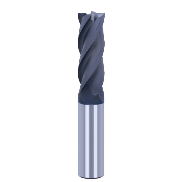
Coating Adhesion and Substrate Matching: Field Failure Analysis of Diamond Coatings for Cutting Tools
We often see a frustrating issue in production: a tool cuts cleanly at first, but sudden edge chipping ruins the workpiece within ten minutes. Operators frequently assume the tool reached the end of its normal life. However, SEM analysis usually reveals that the coating did not simply wear away; it peeled off in sheets like flaking paint, exposing the raw cemented carbide beneath.
The bare tungsten carbide substrate (HRA 92–94) cannot survive direct contact with hard technical ceramics for more than a few seconds. Once the protective layer flakes off, abrasive ceramic dust erodes the tool base into deep pits, causing aggressive tearing along the workpiece rim. When selecting a high-performance diamond coating for cutting tools, mechanical interlocking strength and interface bonding matter far more than raw surface hardness.
Catastrophic Chipping Caused by Delamination: Substrate Cobalt Depletion and CVD Adhesion Control
To understand why coatings delaminate under cyclic cutting shock, we must examine the cobalt (Co) binder in the carbide matrix. Cobalt catalyzes graphitization during CVD, forming a weak graphite layer at the interface that ruins bond strength. When manufacturing a reliable diamond end mill for ceramic, precise chemical cobalt-depletion etching dictates whether the cutting edge can survive real-world impact loads.
Controlling cobalt depletion depth requires fine tuning. If acid etching removes less than 1 µm of cobalt, residual surface cobalt degrades chemical adhesion. Etching deeper than 5 µm leaves a brittle, sponge-like carbide skeleton that fractures under cutting pressure, peeling the diamond film away. Creating a uniform micro-interlocking gradient prevents coating delamination and subsequent edge chipping.
Grain Size Selection: Matching Specialized Diamond Coatings to Specific Ceramics (ZrO2 / Al2O3 / SiC)
Many machinists adopt a one-size-fits-all mindset, assuming any diamond film cuts all technical ceramics equally well. In reality, material mechanics differ drastically: zirconia (ZrO2) causes severe adhesive tool wear, alumina (Al2O3) demands extreme edge sharpness, and silicon carbide (SiC) represents the peak of abrasive hardness. Each ceramic substrate exerts a unique combination of mechanical load and thermal stress on the cutting zone.
We formulate dedicated diamond coating for cutting tools options with tailored grain structures to match these specific material demands. For zirconia or fine-grained ceramics, smooth nanocrystalline coatings reduce friction and eliminate adhesion-driven edge tearing. For abrasive Al2O3 and SiC, microcrystalline diamond films offer superior abrasive resistance and intergranular bonding strength, ensuring stable batch production yields.
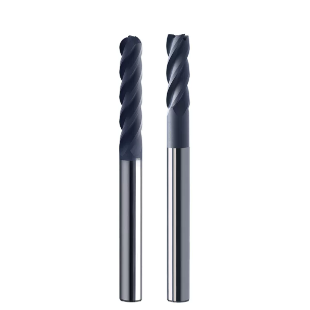
Optimizing On-Site Processes and Toolpaths: Extending Diamond End Mill Life and Eliminating Retraction Chipping
Even with optimized tool geometry and proper coating adhesion, standard metalworking toolpaths will repeatedly fracture ceramic workpiece edges. We frequently encounter shops with high-end spindles and fresh tooling that still break parts at corner transitions or pocket boundaries. The primary cause is not tool quality, but sharp cutting force spikes caused by abrupt changes in tool direction.
Brittle ceramics tolerate continuous steady-state cuts far better than sudden load variations. To maximize the working life of your diamond end mill while preserving crisp part edges, CAM programming must avoid vertical plunges and sharp 90-degree turns. Using smooth toolpath transitions, constant engagement angles, and gradual entry strategies keeps cutting loads well within the material’s fracture limit.
Entry and Exit Strategies: Avoiding Impact Damage via Helical Plunging and Arc Entry/Exit
We once resolved an edge-chipping issue on square ceramic blind holes where operators used straight vertical Z-axis plunges. Direct vertical plunging forced the dead center of the tool into the ceramic with zero surface speed, generating intense axial shock waves that blew out the hole rim. This turned simple entry moves into a primary source of scrap.
We corrected this by implementing helical ramping at a 1° to 2° slope alongside smooth tangential arc entries and exits. Helical ramping distributes axial loads evenly across the cutting flutes rather than concentrating force at the tool tip. Tangential arc exits eliminate edge tearing caused by elastic spring-back during dwell stops, providing an easy way to protect delicate parts using a diamond cutter tool.
Trochoidal Milling and Constant Engagement Angles: Reducing Radial Load Fluctuations for Diamond End Mills on Ceramics
Traditional offset toolpaths in deep pockets or tight corners often cause tool engagement angles to jump from 40° to 180°. For metals, this simply creates thicker chips; for brittle ceramics, the doubled radial side load creates severe leverage that snaps corners or breaks tool necks. Maintaining a constant tool contact angle is critical for edge integrity.
We recommend deploying trochoidal toolpaths with small radial stepovers (ae) for roughing and semi-finishing passes. Running a specialized diamond end mill for ceramic along continuous roll-in arcs keeps tool engagement within a narrow, stable load range. While total path length increases, maintaining steady, high-speed movement lowers radial stress and delivers reliable part-to-part consistency.
Empirical Parameter Ranges: Safety Limits for Spindle Speed (Vc), Feed per Tooth (fz), and Depth of Cut (ap/ae)
Ceramic milling requires high-frequency microscopic spalling rather than heavy roughing cuts. For alumina and zirconia, we keep cutting speeds (Vc) high—between 150 and 300 m/min—which translates to 20,000 to 45,000 RPM on tools under Ø3 mm. High surface speeds minimize cutting resistance and maintain smooth micro-plastic chip evacuation.
Feed rates require strict control: keep the feed per tooth (fz) between 0.002 and 0.01 mm/tooth, with shallow axial depths (ap: 0.05–0.3 mm) and light radial stepovers (ae ≤ 10% of tool diameter). For final finishing passes, pairing round nose end mills with micron-level stepovers ensures chip thickness stays below the micro-crack threshold, providing a safe, repeatable cutting window.
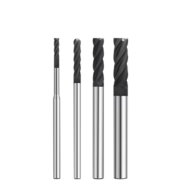
Coolant and Chip Evacuation Management: Preventing Thermal Shock Damage and Tool Wear
Many machine shops focus entirely on spindle speeds and feeds, treating cutting fluid as a minor detail. While troubleshooting edge-chipping on-site, we frequently find that poorly aimed coolant lines cause invisible thermal micro-cracks. Ceramics have low thermal conductivity, and the intense frictional heat generated at the cutting interface creates steep internal stress spikes that easily shatter delicate parts.
Intermittent cooling in the cut zone triggers rapid thermal cycling, inducing severe tensile stress that fractures edges like brittle glass. Protecting the coating integrity and substrate of your diamond end mill requires a continuous, high-volume fluid barrier. A well-managed flow field instantly flushes away grinding heat and micro-powder before thermal shock can damage the workpiece.
High-Pressure Wet Cooling vs. MQL: Balancing Chip Flushing Force and Thermal Stress
For extremely hard, dense materials like silicon carbide or alumina, we rely on symmetrical high-pressure flood cooling at 15 to 30 bar. High-pressure delivery provides the kinetic energy needed to penetrate the vapor barrier, stabilize cutting temperatures, and blast away abrasive slurry. This continuous thermal envelope prevents brittle micro-spalling caused by localized heat concentration.
However, ultra-thin ceramic substrates or delicate micro-features can crack under sudden fluid thermal shock. For these sensitive finishing passes, we switch to cold air combined with Minimum Quantity Lubrication (MQL) using vegetable oil mist. A high-velocity air blast clears dust from the path of your diamond end mill for ceramic, preventing abrasive packing without subjecting thin walls to liquid thermal shock.
Mitigating Abrasive Slurry Damage on Diamond Cutter Tool Edges
Ceramic milling generates fine, highly abrasive mineral dust rather than continuous metal curls. Without rapid chip evacuation, these suspended particles mix with fluid to form an aggressive lapping slurry. As the tool spins, this slurry rapidly scours the flank face and erodes the honed edge, causing a sharp spike in cutting forces.
This secondary abrasion can undercut diamond grain adhesion, degrading even a premium diamond cutter tool prematurely. To stop this wear cycle, we mandate dual-opposed air or coolant nozzles paired with 5 µm multi-stage filtration. Keeping recirculated fluid free of abrasive fines protects both the micro-geometry of the cutting edge and the finished part profile.
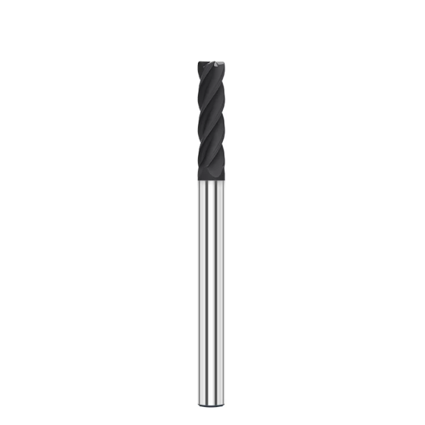
Supply Chain and On-Site Testing: Evaluating Key Metrics for China Diamond Coated Carbide End Mills
Shop managers in Europe and North America frequently ask how to evaluate tooling when brand prices vary drastically across the market. Ceramic machining offers zero tolerance for edge defects, making initial sample cuts misleading. Many tools perform well on the first two passes but trigger widespread edge-chipping on the tenth part as lower-tier coatings fail.
Auditing a dependable china diamond coated carbide end mill requires looking beyond initial test runs to evaluate batch-to-batch consistency and substrate prep. Consistent performance depends on edge-honing control, cobalt-leaching depth, and polished flute geometry. Translating these critical features into measurable receiving metrics protects your production line from unpredictable tool failures.
Workshop Testing Protocols: Dynamic Balance, Full-Stroke Runout, and Batch Consistency
When a new tool batch arrives, operators should never load them straight onto expensive ceramic blanks. Our standard qualification protocol begins offline on a dynamic presetter, inspecting edge-honing radius under high magnification and verifying total indicated runout. If radial runout exceeds 3 µm at the tool tip, we reject the tool immediately.
We follow this with a controlled trial run across 20 to 50 test parts, monitoring edge-chipping trends on an optical profilometer. A qualified diamond end mill for ceramic should exhibit gradual, predictable edge wear rather than sudden, catastrophic coating failure. If you are struggling with sporadic tool breakdowns, establishing this incoming runout and edge-honing audit is the fastest way to stabilize your process.
Avoiding Low-Quality Coatings: Essential Criteria for Qualifying Diamond End Mill Suppliers
Substandard diamond recoating and uncontrolled chemical etching are common causes of sudden edge delamination. Budget suppliers often rush deposition without neutralizing surface cobalt, creating a weak interfacial graphite layer that flakes off under impact. We require raw tungsten carbide substrates to use 0.4–0.6 µm ultra-fine grains with certified CVD scratch-adhesion ratings.
When vetting specialized diamond end mill suppliers, discussions should focus on technical specifications rather than generic material lists. Experienced suppliers can provide dedicated rake angles, optimized edge preps, and tailored diamond grain sizes for your exact ceramic grade. If you are screening new vendors, requesting cobalt-etching depth logs and edge-honing inspection data quickly filters out non-manufacturing trading companies.
Cost Per Part (CPP) Analysis: Lowering Scrap Rates with China Diamond Coated Carbide End Mills
Procurement teams often focus solely on unit tool purchase price, which can inadvertently drive up total production costs. High-purity ceramic blanks and pre-sintering stages are costly; scrapping a finished part due to edge-chipping costs far more than the end mill itself. We always urge engineers to evaluate processes using a strict Cost Per Part (CPP) model.
Deploying a process-controlled china diamond coated carbide end mill with a tool-life standard deviation under 5% enables predictable preventive tool changes while keeping yields above 98%. If you are reviewing a challenging ceramic print or struggling with high scrap rates, we can help review your part tolerances, spindle setup, and coolant strategy to build a chipping-free machining process.






