
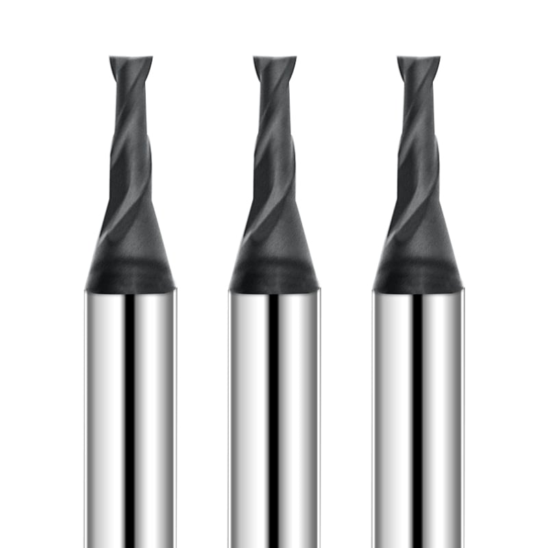
Last month, an urgent call came in from a German automotive mold shop. During Electrical Discharge Machining (EDM), an entire batch of high-density isostatic graphite electrodes ran out of tolerance. The result was catastrophic: a complete set of precision mold cavities had to be scrapped. The shop operators were baffled because spindle loads had looked normal, no catastrophic workpiece chipping had occurred, and the tools still felt sharp enough to cut material.
When we inspected those tools under a 100x optical microscope, the root cause was obvious. The CVD diamond coating at the corner radius had partially delaminated. Instead of cleanly shearing the material, the tool had been forcibly extruding graphite under severe friction and localized pressure. Over 15 years of supporting mold shops across the US and Europe, we have seen this costly mistake repeatedly: treating the bare ability to cut as the true benchmark for tool life.
Due to the abrasive, brittle nature of graphite, tool failure rarely happens all at once. Even if the outer diameter of diamond-coated end mills for graphite wears down by just 5 to 8 microns, or if the wiper edge suffers microscopic dulling, cutting forces spike dramatically. This creates hidden defects like edge pull-out, thin-rib deflection, and dimensional drift. As frontline diamond-coated end mills manufacturers, we know that keeping part costs down depends on knowing exactly when to pull the tool.
Are the cutters running in your high-speed spindles right now actually making good parts, or are they silently destroying your mold tolerances?
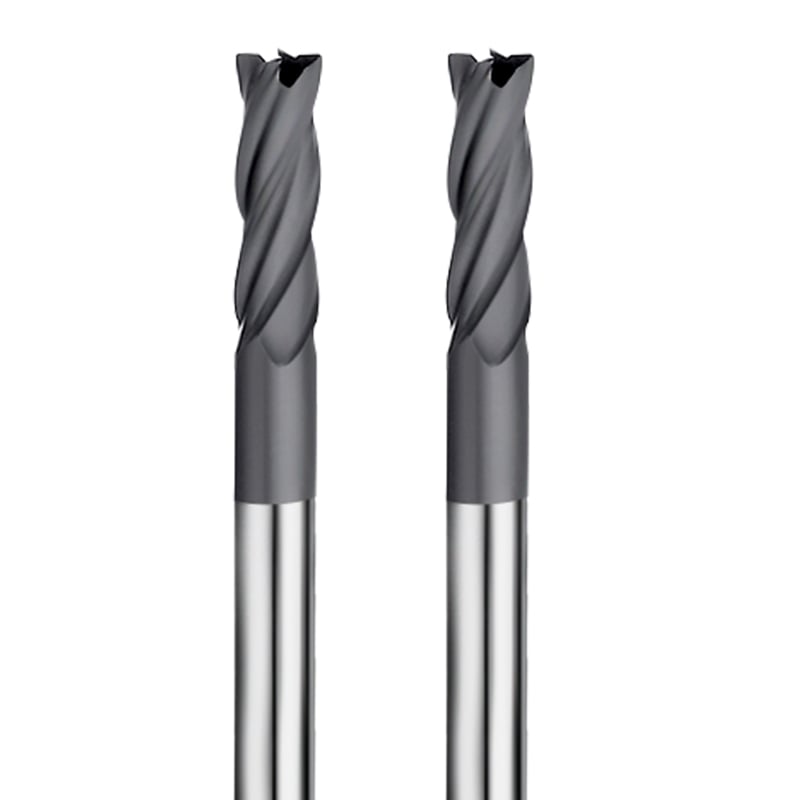
1. Micro-Chipping and Grain Pull-Out at Graphite Edges — The First Warning Sign of Wear
Unlike metals that produce visible chips, graphite fractures into micro-fine dust. This makes it impossible to evaluate edge condition by looking at chip formation. Many operators wait for visible chunks to break off the part before swapping tools. In high-precision electrode manufacturing, the effective cutting life of diamond-coated end mills for graphite is already over the moment you spot subtle “whitening” or slight grain pull-out along top edges.
When machining thin-walled aerospace or medical components, edge integrity is non-negotiable. Micro-flaking along sharp edges indicates that the diamond crystal matrix on the tool’s rake and flank faces has worn unevenly. Running the tool past this point might seem to save tooling budget on paper. In reality, fractured graphite grain boundaries cause severe localized arcing during EDM burning, leading to costly electrode scrap.
Abnormalities at Climb Milling Exit Points (Exit Chipping): From Shearing to Crushing
When climb milling graphite contours, a sharp diamond edge cleanly shears through the brittle carbon lattice upon tool entry and exit. If you inspect the part and notice jagged micro-notches (exit chipping) right where the tool disengages from the corner, the cutting edge on your graphite cutting end mills has lost its micro-sharpness.
At this stage, the tool is no longer slicing the carbon matrix; the exposed carbide substrate is forcibly crushing it at high surface footage. CAM programmers often try to hide this with arc-in/arc-out deceleration paths. While that may temporarily mask the chipping visually, it only prolongs the life of a dull tool. We always advise setting a tool change command the moment exit chipping appears.
Sharp Cutting Resistance Spikes on Ultrafine Isostatic Graphite
Many machinists assume that ultrafine graphite (grain sizes below 5 microns) is easier to cut because of its smooth finish. In practice, dense isostatic grades create intense microscopic abrasion against the cutting edge. After continuous high-speed runs, the thin CVD film on diamond-coated carbide end mills gradually thins down to the substrate, significantly increasing the cutting edge radius.
This edge rounding causes cutting forces to rise exponentially. In our field cutting force studies, radial tool pressure increases dramatically long before a CNC spindle overload alarm ever trips. This added load stresses the brittle workpiece, causing subsurface micro-cracks. If an operator has to dial down the feed rate override to maintain clean edges, the coating is worn out and the tool must be changed.
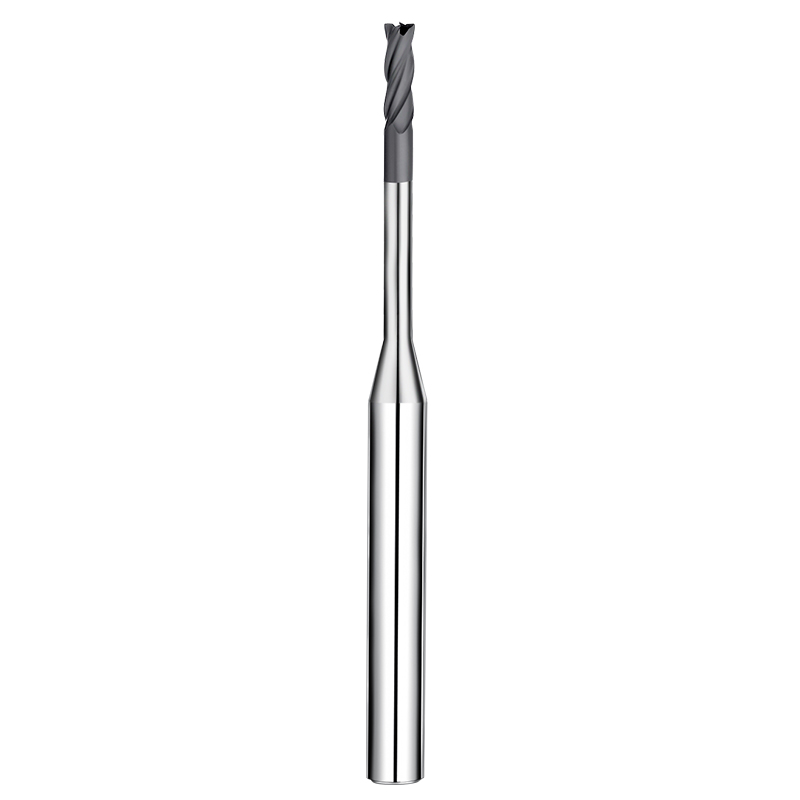
2. Dimensional Tolerances Drifting Negative — The Red Line for Radial Wear
When batch-milling graphite parts, finding negative dimensional drift on your CMM report is a clear warning. Graphite dust continuously abrades the peripheral flutes of graphite cutting end mills. If your CNC machine is equipped with a laser tool setter, you will notice that tool diameter wear does not drop off a cliff suddenly; instead, it shows a steady, deceptive linear decay.
Operators often try to offset this wear by adjusting tool radius compensation (D-values) in the CNC controller. While this keeps roughing dimensions acceptable, it is dangerous during finishing passes. Once peripheral wear exceeds a critical limit, the tool’s clearance angle rubs against the cut surface. This causes asymmetrical deflection, meaning tool compensation only hides the fact that the tool geometry is ruined.
Tool Replacement Thresholds for Thin-Walled EDM Rib Electrodes
When milling fragile rib features with wall thicknesses between 0.3 mm and 0.5 mm, radial tool wear translates directly into rib taper and base thickness errors. An end mill for graphite running with worn flutes pushes against the flexible rib rather than cutting it cleanly. For our precision tooling clients, we never rely on run time alone; we enforce a strict 0.005 mm top-to-bottom thickness tolerance threshold.
If your CMM or optical comparator detects a trapezoidal taper along a rib, or if thickness varies by more than 8 microns across a 5-part batch, replace the cutter immediately. Thin graphite features have virtually no tensile strength. The extra radial force from a slightly worn cutter will easily trigger chatter at the floor of deep slots, snapping the electrode right before cycle completion.
The Cascading Scrap Risk of Micro-Wear in EDM Spark Gap Control
Focusing solely on CNC cycle times often blinds shops to the expensive downstream risks in the EDM sinker cell. Finishing spark gaps are typically preset between 0.015 mm and 0.03 mm. If an undetected 0.01 mm radial wear occurs on your diamond-coated carbide end mills, the actual spark gap is distorted by more than 30%.
This geometric distortion prevents discharge energy from dispersing evenly across the electrode face. The result is incomplete corner burning, side-wall carbon accumulation, and localized over-burning inside the hardened steel cavity. In over 90% of the mold scrap cases we analyze, the root cause traces back to an overused graphite cutter. It is far cheaper to swap a cutting tool early than to scrap a hardened tool steel cavity insert.
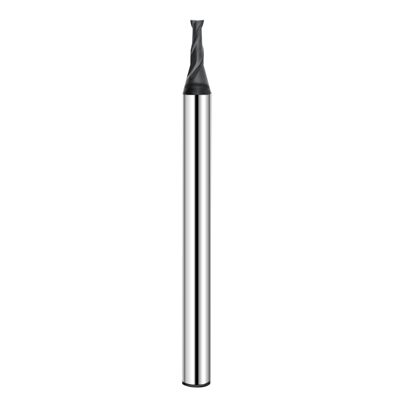
3. Coating Delamination at the Corner Radius — Failure Characteristics of Graphite Corner Radius End Mills
During deep-cavity clearing and bottom root-cleaning, sharp square cutters often suffer premature tip chipping. Most mold shops naturally switch to graphite corner radius end mills (bull-nose cutters) to achieve stable, high-speed contouring. However, wear patterns on radiused tools are subtle. While peripheral and bottom flutes may appear completely intact, microscopic coating failure often begins right at the corner tangent point where mechanical stress peaks.
When troubleshooting electrode machining for automotive grille and tire molds, we frequently see operators run these tools for hours as long as the tip is not snapped. But continuous 3D contouring exposes the radius transition to extreme abrasive shearing. Once this micro-layer fails, the tool’s actual cutting radius deviates from the CAM nominal geometry, ruining programmed blends and cavity profiles.
Identifying CVD Coating Delamination in High-Stress Zones
During simultaneous 3-axis milling, the corner radius experiences the sharpest fluctuations in surface footage and load. Inspecting the tool under a 50x–100x shop microscope will quickly reveal its true condition. The presence of irregular, fish-scale bright spots or localized voids along the outer arc confirms that the crystalline film on your diamond-coated end mills for graphite has delaminated from the tungsten carbide substrate.
Unlike gradual abrasive wear, coating delamination is sudden and catastrophic. The moment the diamond film peels away, the bare substrate is exposed to abrasive graphite dust without lubrication. Severe cratering usually develops within 10 to 15 minutes. In our shop practice, any continuous delamination exceeding 0.05 mm along the radius requires immediate tool retirement or downgrading to roughing.
Stepped Defects and Witness Marks at the Cavity Floor Junction
When a radius tool wears unevenly or suffers micro-flaking, the defect shows up immediately at the intersection between the workpiece floor and sidewall. If you notice tiny steps, ridges, or visible shadow lines between step-over passes when finish-milling clearance pockets, your diamond coated carbide end mills have lost their true corner radius profile.
While these subtle step defects seem minor on raw graphite, they replicate directly into hardened mold steel during sinker EDM. Bench polishers then have to spend costly manual hours stoning out the resulting ridges. Pushing a worn cutter to save a few tooling dollars always costs more in benchwork. A stepped transition at the fillet is a definitive sign to change the tool.
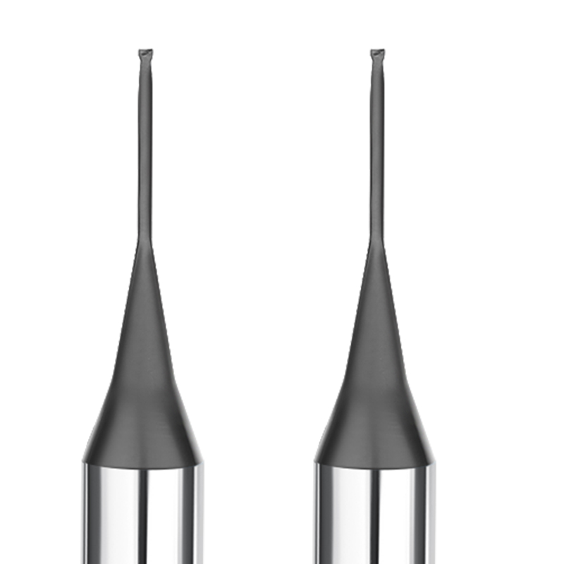
4. Shift in Cutting Acoustics — Detecting Dulling via Audio and Spindle Feedback
Inside an enclosed graphite machining center, your ears are often faster and more reliable than digital probes. A premium diamond coated end mill in prime condition creates a faint, crisp “swishing” sound as it glides through isostatic graphite. This clean acoustic signature confirms that the micro-cutting edges are actively shearing carbon particles rather than rubbing against them.
As the cutting edge dulls, that high-frequency sound transitions into a low, muffled humming or grinding noise. In high-volume mold shops, this acoustic shift typically shows up 1 to 2 hours before the machine’s control panel registers an electrical load alarm. Hearing a dull grinding tone during finish passes indicates that flank friction and contact temperatures have crossed critical thresholds.
Spindle Load Monitoring vs. Friction Noise at 20,000+ RPM
At spindle speeds above 20,000 RPM, small-diameter graphite cutting end mills generate minimal baseline cutting torque. Because of this, built-in CNC load meters remain relatively unresponsive during early wear stages. Waiting for the spindle load meter to jump by 5% to 10% usually means the cutter is already failing and generating excessive frictional heat.
On the shop floor, we cross-reference acoustic changes with minute current ripples in the axial servo drives. If a dull grinding sound is accompanied by faint micro-vibrations in the feed axis, cutting forces have multiplied even if the spindle meter stays green. Continuing to cut under these conditions risks flexing thin-walled ribs and introduces excessive radial loads to high-speed spindle bearings.
How Trapped Graphite Dust Accelerates Secondary Flank Wear
Graphite dust evacuation is a double-edged sword. When your end mill for graphite is razor-sharp, high-velocity vacuum hoods instantly pull fine carbon powder away from the cut zone. But as soon as the edge dulls and begins compressing the stock, trapped dust forms an abrasive slurry between the tool flank and the cavity wall.
These loose, ultra-hard carbon particles act like rotating sandpaper against the exposed carbide core. Once the coating is compromised, flank wear land width expands rapidly within a matter of minutes. More than half of sudden tool breakage incidents stem from ignoring these early acoustic shifts, allowing secondary abrasive dust to hollow out the carbide tip.
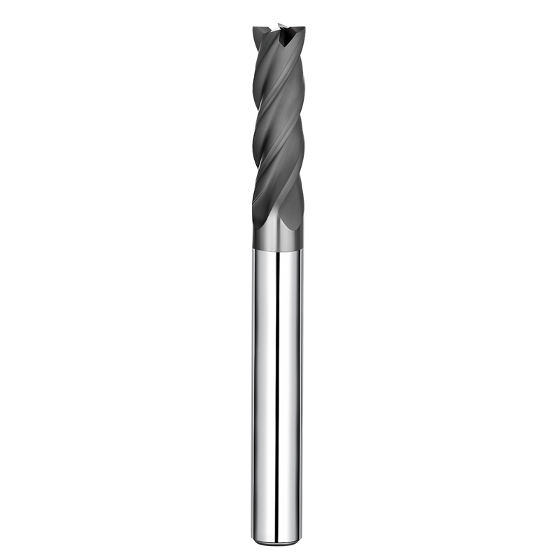
5. Surface Finish Degradation and Color Darkening — Loss of Polish-Free Quality
A quick visual inspection of a finished graphite electrode tells you everything about cutter health. A part milled with a healthy end mill for graphite exhibits a uniform, dark-gray sheen or a consistent satin-matte texture. This clean visual finish confirms that the tool’s wiper edge is cleanly cleaving the micro-grain matrix rather than tearing it open.
When the machined surface turns dull, powdery, or shows blotchy gray patches under direct inspection lighting, the tool’s wiper flat and micro-clearance have worn out. Graphite responds instantly to edge blunting. A measurable jump in surface roughness (Ra/Rz) always occurs well before outer diameter dimensions fail on a CMM, signaling an immediate drop in process control.
From Matte Sheen to Granular Voids: Wiper Edge Failure Modes
Under high magnification, graphite removal mechanisms depend entirely on edge sharpness. When the peripheral and end wiper flutes on diamond coated carbide end mills remain sharp, graphite grains are sliced cleanly. When the micro-edge rounds over, the cutting action turns into tensile pulling and tearing, creating microscopic pits across the surface.
You can diagnose this by feel: if a silky surface gives way to a chalky drag that leaves carbon residue on your fingers, the wiper geometry has failed. In our precision milling cells, visible grain pull-out under 10x magnification triggers an immediate tool replacement, even if the electrode dimensions still pass coordinate checks.
Mandatory Tool-Change Thresholds for Polish-Free EDM Electrodes
Demanding mold segments—such as optical tooling and micro-connector cavities—rely heavily on polish-free graphite electrodes. If an electrode’s surface roughness climbs above Ra 0.4–0.6 µm, the spark-eroded steel cavity will mirror those flaws, forcing bench hands to polish the mold manually. For these parts, tool life limits must tie directly to surface finish thresholds.
We advise our clients to enforce a strict tiered routing policy for their diamond coated end mills. As soon as a finishing cutter exhibits minor surface haze or loss of luster, swap it out immediately and downgrade it to roughing or semi-finishing operations. This maximizes total tool usage while guaranteeing that every electrode sent to the EDM sinker cell delivers a true polish-free burn.
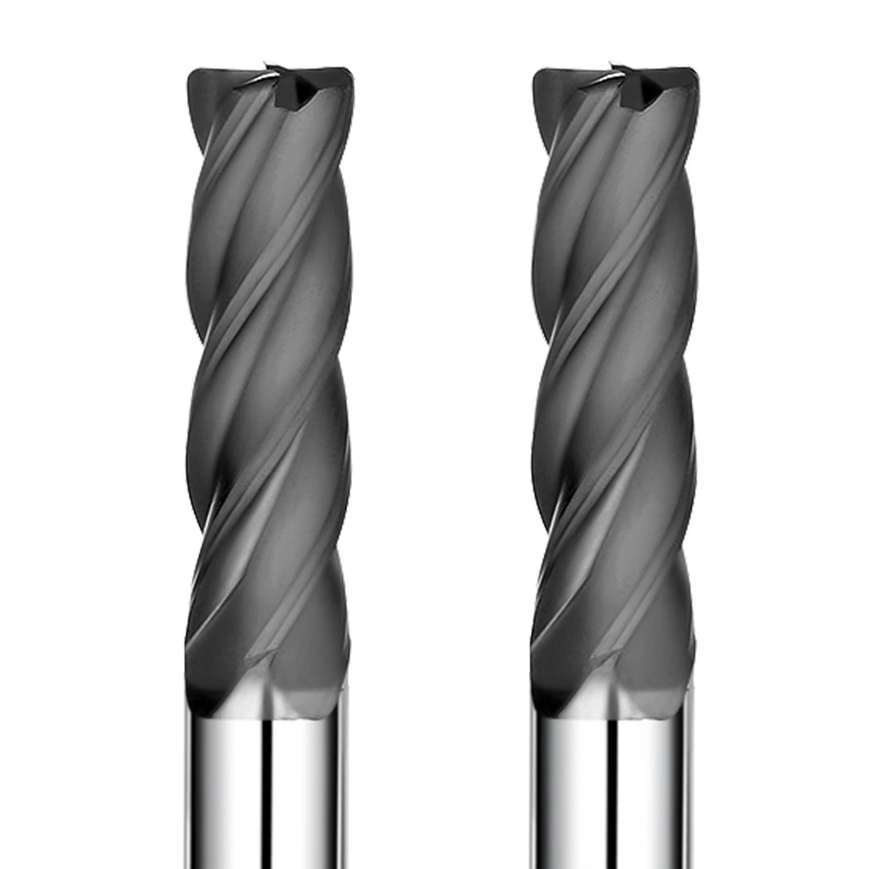
6. Tool Overhang and Chatter in Deep Cavities — Reduced Rigidity and Deflection
Machining deep mold cavities or tall graphite electrodes often requires significant tool overhang. When the length-to-diameter ratio exceeds 5:1—or reaches 8:1 and higher—the overall rigidity of the setup drops precipitously. Sharp graphite cutting end mills maintain stable paths through light shearing forces. However, even slight edge wear increases cutting resistance enough to instantly trigger tool deflection and chatter.
If you notice evenly spaced wave patterns or fish-scale marks along deep vertical walls, the issue is rarely just spindle rigidity or part clamping. In our field troubleshooting, excessive radial push from a dulled cutting edge is almost always to blame. When the tool rubs rather than shears, high-frequency vibration deflects the slender shank and leaves permanent surface defects on the electrode.
Tool Deflection and Sidewall Taper on Neck-Reduced Tools
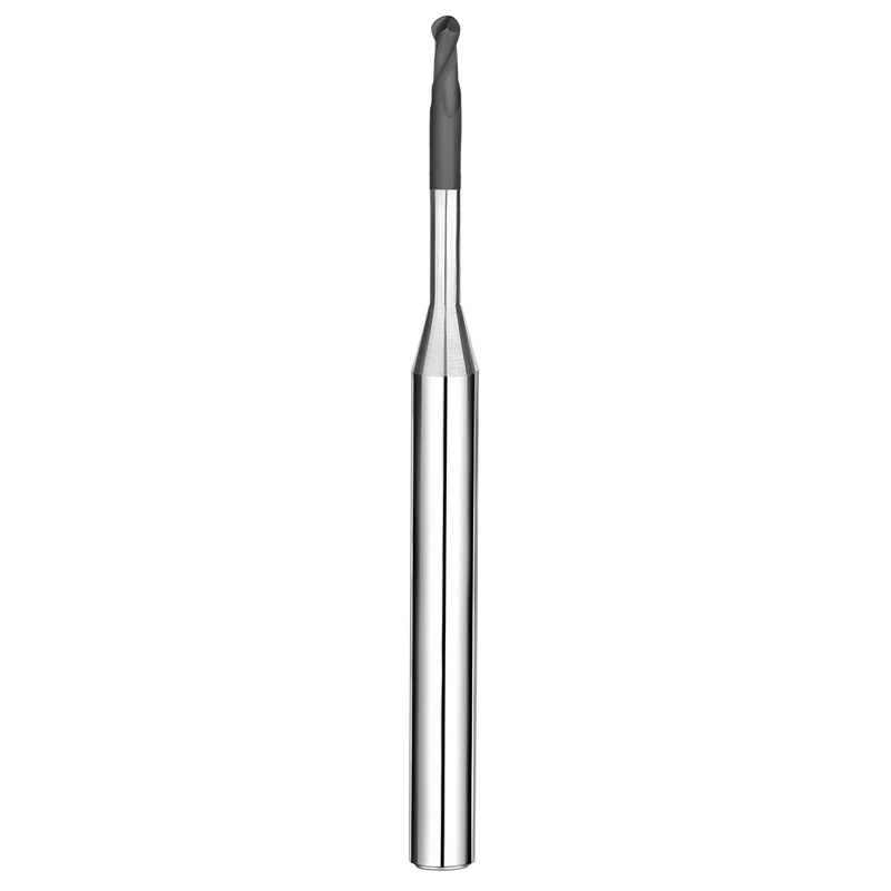
Reaching into deep ribs requires neck-reduced geometries, but relieving the neck reduces the tool’s bending resistance. As the outer flutes on diamond coated end mills for graphite begin to wear, the required lateral cutting force climbs sharply. This pushes the relieved neck off-axis, creating elastic tool deflection that is immediately visible on a CMM inspection report.
This deflection causes severe sidewall taper—leaving parts thicker at the floor—and makes deep slots significantly undersized. In our shop testing, if sidewall perpendicularity error widens from 0.005 mm to over 0.015 mm across a batch, the flank wear can no longer support long-reach machining. Swapping in a fresh tool is far more reliable than chasing dimensions with CNC offsets.
Micro-Vibration and Internal Substrate Interface Damage
Long-overhang chatter does more than ruin surface finishes; it destroys the internal tool structure. Premium diamond coated carbide end mills use ultra-fine-grained, low-cobalt carbide substrates designed for high hardness and wear resistance. When subjected to continuous chatter during deep cuts, intense alternating stresses concentrate directly at the tool tip and coating boundary.
These micro-impacts cause fatigue along the interface between the CVD diamond film and the carbide substrate, leading to microscopic delamination and hidden fractures. Our metallurgical lab inspections show that chattering tools frequently suffer internal bond failure long before they snap. When high-frequency squealing cannot be cleared by tuning feeds and speeds, replace the tool immediately to prevent sudden breakage.
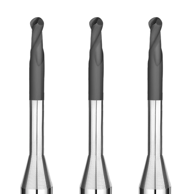
7. Sudden Tool Breakage from Overrunning Lifespans — Preventive Tool Management
In high-volume electrode shops, operators often try to maximize tool life by running cutters until they physically break. While dry graphite milling avoids extreme thermal shocks, the abrasive mechanical wear is relentless. The instant the diamond layer is breached and the carbide core wears away, diamond coated carbide end mills will snap in milliseconds, gouging expensive, near-finished workpieces.
Our 16 years of shop tracking show that scrap rates spike drastically during the final 10% of a cutter’s lifespan. Squeezing an extra hour out of an inexpensive tool is not worth destroying an imported isostatic graphite block and losing dozens of prior machining hours. Mature machine shops never push tools to their physical limit; they enforce strict preventive tool-change schedules.
Setting Early Warnings with Cutting Distance and Spindle Time
The most effective way to prevent catastrophic failures is tracking linear cutting distance alongside spindle run time in your CNC controller or MES. For standard pocketing with diamond coated end mills for graphite, we establish baseline wear data across 5 to 10 test tools. We then set a mandatory tool replacement threshold at 80% to 85% of that average failure point.
Integrating these limits into macro programs lets your machine automatically swap to a redundant tool or pause the cycle before failure occurs. While this may seem to retire a tool with minimal life remaining, it delivers rock-solid process reliability and eliminates midnight spindle crashes. That level of predictability is essential for automated, lights-out electrode production.
Balancing Consistent Tool Life and Sudden Chipping
Across volume production, tool life consistency is far more important than the peak performance of a single cutter. Inconsistent diamond coated end mills manufacturers often deliver tools with wild variations in run time—one tool runs for shifts while the next chips in minutes due to poor substrate preparation or uneven cobalt leaching.
Our manufacturing focus centers on precise carbide grain sizing and uniform micro-edge honing across every production lot. This guarantees a narrow, predictable wear band on every cutter. When you source from manufacturers with tight process controls, you eliminate tool breakage anxiety, stabilize your scrap rates, and maintain true lights-out machining reliability.
Implementation Advice: Establishing Tool Retirement Standards with Manufacturers
The seven warning signs—edge chipping, negative tolerance drift, radius flaking, grinding acoustics, surface hazing, deep-wall taper, and sudden breakage—are connected indicators of tool wear. Machine shops that achieve low cost-per-part metrics never guess when to swap cutters. Instead, they partner with specialized diamond coated end mills manufacturers to turn physical wear symptoms into clear, measurable tool retirement rules.
Standardizing this workflow does not require an overhaul of your shop floor. Shifting from reactive firefighting to active process control starts with simple microscopic spot checks and spent-tool scrap analysis. If you are auditing your current graphite machining cell, these two lightweight practices will help you map the exact wear curves of your tooling.
Integrating 100x Microscopic Spot Checks with Rapid Tool Changes
A portable 100x optical microscope at the machine workstation provides instant clarity. When running production batches with diamond coated end mills for graphite, operators should perform a 30-second inspection at preset part intervals. They can quickly scan the corner radius blend, outer flank wear lands, and wiper flats right at the tool station.
If you are milling thin ribs or high-precision EDM electrodes, establish clear visual scrap criteria—such as flank wear exceeding 0.03 mm or any micro-flaking along the radius. Retiring cutters at this inspection stage and downgrading them to roughing operations eliminates electrode chipping, ensures mirror-like burns, and bases your tool changes on solid data.
Diagnosing Machine Runout, Balance, and Dust Evacuation from Spent Cutters
Used cutters serve as diagnostic recorders for your entire machining process. When inspecting worn diamond coated carbide end mills, asymmetric flute wear—where one cutting edge is stripped while the other looks new—points directly to excessive total indicated runout (TIR). Check your tool presetters, collets, and shrink-fit holders to ensure dynamic runout remains under 3 microns.
Similarly, fine abrasive scratching along the flute roots or early micro-chipping in deep slots points to inadequate vacuum velocity or misaligned air blasts. In many cases, premature tool failure is caused by trapped graphite dust recutting inside the pocket rather than coating quality. If you are troubleshooting complex electrode prints, dense isostatic graphite grades, or severe deep-cavity wear, feel free to reach out to review your parameters and tool geometries.






