
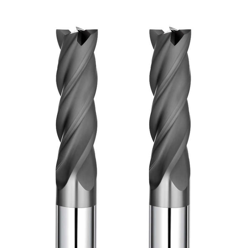
Earlier this year, our team assisted engineers at a German mold shop in troubleshooting a batch of isostatic graphite electrodes for precision injection molds. The parts showed surface hazing, dusting, and micro-scoring. Although the spindle ran at 28,000 RPM using a standard end mill for graphite, the post-EDM surface roughness stayed above Ra 1.6 µm. Micro-chipping was also visible along the thin rib edges.
We have seen this scenario repeatedly over the past 15 years while supporting machine shops worldwide. Graphite fractures in a brittle mode rather than forming ductile chips. When surface finish degrades, operators often slow the feed rate or blame the dust extraction. However, actual cutting data shows that the issue usually stems from subtle setup and tooling factors:
- Dynamic runout: Tip runout above 0.005 mm turns multi-flute milling into single-flute hammering, causing brittle spalling.
- Coating delamination: When diamond coated graphite end mills experience microscopic edge wear, cutting forces surge and push the material instead of shearing it cleanly.
- Tip dead zones: Using a ball nose end mill for graphite flat against a surface drops the center cutting speed to zero, leaving cloudy drag marks. Deep-pocket chatter can likewise make custom graphite end mills necessary to maintain reach and rigidity.
Does your machine run cleanly right after a tool change, only for the surface finish to drop once the cutter reaches full depth in a critical cavity?
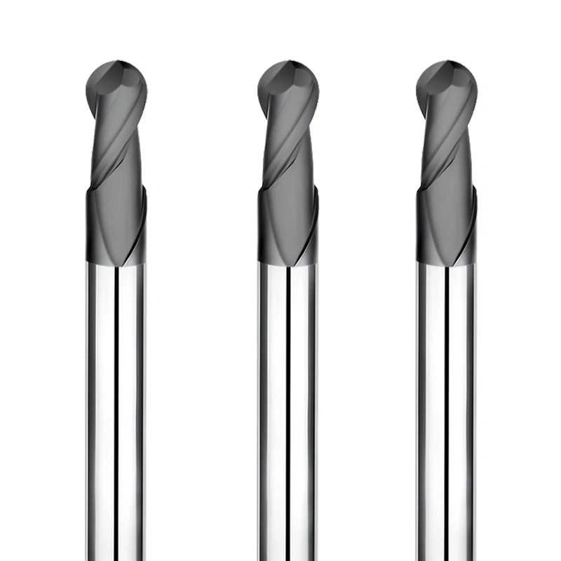
Diagnosing Common Graphite Surface Defects: Why Do Scuffing and Dusting Persist Even When Using the Right Graphite End Mill?
Many machinists assume that high spindle RPM paired with a dedicated graphite end mill guarantees a clean, satin-like surface. However, our field experience shows that dullness, tearing, and fine dust adhesion still occur frequently on dedicated setups. Graphite is brittle and isotropic; material removal relies on micro-crack propagation rather than plastic shear deformation.
When system rigidity or chip clearance falls out of balance, controlled micro-fracturing turns into destructive tearing. Under magnification, surface dusting is crushed powder left by a worn cutting edge. Scuff marks appear when trapped dust passes under the tool flank. Resolving these issues requires looking past basic tool life and analyzing the cutting dynamics at the micro level.
Distinguishing Between Spalling and Micro-Chipping on Graphite Electrodes: Troubleshooting Spindle Runout and Wobble with Graphite End Mills
During a recent setup, a client reported fish-scale pitting along the vertical walls of finish-milled electrodes. The operator suspected early edge failure on the graphite end mills. However, checking the tool tip with a dial indicator revealed 0.012 mm of dynamic runout. With a finishing feed of 0.008 mm per tooth, runout exceeded chip load, forcing one flute to take the entire cut.
This cyclic impact dislodges graphite grains in clusters, leaving clear spalling pits. We advise checking total indicator reading (TIR) at the tool tip before swapping tools, keeping it under 0.003 mm. Graphite dust inside an ER collet or an unbalanced retention knob is often the real cause. Cleaning the taper and moving to a shrink-fit or hydraulic holder usually restores surface roughness below Ra 0.4 µm.
Sidewall Ripples and Dimensional Taper Errors: Avoiding Elastic Deflection in Diamond-Coated Cutting Tools Due to Excessive Overhang
When milling deep ribs or tall vertical walls, parts often finish oversized at the bottom with visible light-and-dark bands along the sides. Our tests show that when diamond coated cutting tools exceed a 5:1 length-to-diameter ratio, even minor radial loads cause micron-level deflection in the carbide core. This deflection creates taper error and causes periodic spring-back chatter on sidewalls.
Simply reducing feed rates rarely solves this problem, as low chip loads increase rubbing on brittle stock. Instead, apply stepped-depth passes or choose thick-shank tools with neck relief to improve core rigidity. If long reach is unavoidable, leave a uniform 0.05 mm for finish passes and limit radial engagement (ae) to under 2% of the tool diameter to minimize side deflection.
Corner Collapse and Thin-Rib Breakage: Cutting Force Distribution with Standard vs. Custom Graphite End Mills
Edge chipping on thin ribs (around 0.3 mm) and corners remains a frequent bottleneck. Standard end mills see engagement jump from 90° along straight walls to 180° in sharp corners. This spike in cutting force creates tensile stress that fractures fragile graphite edges along grain boundaries. When standard profiles cannot clear dust or hold rigidity in tight pockets, custom graphite end mills provide a more balanced solution.
Custom geometries optimize helix angles, apply unequal flute indexing, and add micro-negative chamfers to redirect cutting forces inward as compressive support. If custom tooling is not immediately on hand, adapt your toolpath programming: use trochoidal milling or corner roll-in radii to smooth out sudden engagement spikes. This simple CAM change prevents over 80% of edge-chipping failures on fragile ribs.
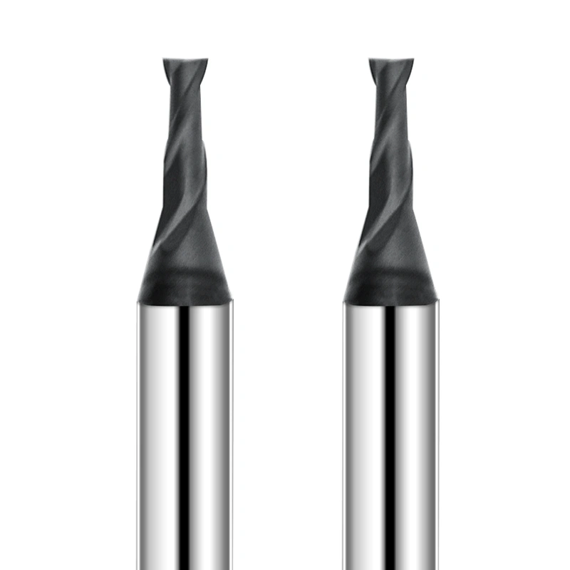
Assessing Tool Wear and Edge Condition: The Critical Threshold for Diamond Coated Graphite End Mills
In daily production, machinists often judge tool life solely by cutting hours or whether the edge still looks shiny. Unlike ductile metals, graphite is extremely sensitive to micro-changes in edge geometry. While premium diamond coated graphite end mills hold tight tolerances for long cycles, this durability can create a false sense of security, leading operators to run cutters past their prime.
Once the diamond film sustains initial micro-damage, degradation accelerates quickly. As the tungsten carbide substrate becomes exposed, abrasive graphite particles rapidly expand the edge hone radius. The tool stops shearing cleanly and begins plowing into the stock. This transition turns the surface chalky white, causes finish readings to spike, and triggers edge breakout on thin features.
Distinguishing Between CVD Coating Flaking and Substrate Wear: When Should You Replace Your Diamond Coated Graphite End Mills?
When inspecting worn tools under a 200x toolmaker’s microscope, we often find that localized darkening on the rake face is actually coating delamination rather than uniform abrasive wear. For diamond coated graphite end mills, once the diamond film flakes away from the carbide core, abrasive dust cuts deep craters into the exposed substrate within minutes.
Checking the flank wear land (VB) is the most reliable way to monitor tool health on the shop floor. When flank wear reaches 0.03 to 0.05 mm, or when the evacuation dust shifts from loose grain to a fine, smoky mist, relief clearance is lost. Swapping out the tool at this threshold prevents cutting forces from introducing subsurface micro-cracks into your electrodes.
Cutting Edge Micro-Chipping Causes Roughness: Optimizing Feed per Tooth (fz) for Diamond Coated Cutting Tools
To chase high surface finishes, machinists sometimes drop the feed rate below 0.002 mm per tooth. Our dynamometer cutting data shows that this practice often backfires on diamond coated cutting tools. Because diamond films add a small edge hone radius, an undersized chip load prevents the cutting edge from penetrating the stock cleanly.
Instead of shearing, the tool slides and rubs against the graphite surface, driving high-frequency vibration and micro-chipping along the diamond edge. We recommend maintaining a finishing chip load between 0.005 and 0.012 mm per tooth. Staying above the critical shear thickness ensures clean brittle chip removal while protecting the ultra-hard edge from rubbing damage.
Secondary Dust Rubbing Effects: Evaluating China Graphite End Mill Consistency via Flute Polish
During high-speed dry milling, evacuated graphite dust travels through tool flutes at extreme velocity. When testing batches of a china graphite end mill, we find that the surface finish inside the flute profile directly impacts workpiece quality. Rough grinding marks or coating nodules inside the flutes cause fine dust to pack and drag across finished walls.
This secondary rubbing leaves dull, hazy streaks with uneven light reflectivity across the electrode. When evaluating volume tool shipments, inspect the flute polish and transition smoothness. Mirror-polished flutes paired with high-volume dust extraction ensure particles clear the cut zone in milliseconds, preventing reground dust from marring critical surfaces.
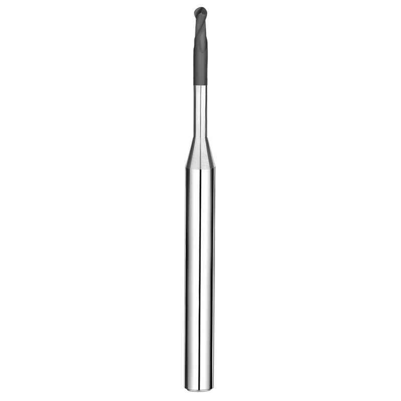
3D Surface and Finishing Defect Strategies: Toolpath and Stepover Tuning for Ball Nose End Mill for Graphite
Finishing complex 3D contours on EDM electrodes is often the most demanding machining phase. Even with uniform semi-finishing stock, switching to a ball nose end mill for graphite can still produce fish-scale textures, cloudy patches, or profile deviation. Graphite lacks ductility, making changing surface angles prone to micro-fracture under fluctuating cutting loads.
Eliminating these flaws requires matching the tool’s contact point, linear surface speed, and cutting force vectors. Standard metalworking CAM toolpaths often struggle with graphite’s instant brittle chip formation. By balancing stepover values, controlling effective cutting diameters, and steering clear of the tip dead zone, you can achieve uniform surface texture on complex 3D profiles.
Eliminating Surface Scallops: Optimizing Stepover and Tilt Angles for Ball Nose End Mill for Graphite
Whitish ring patterns often appear on shallow curves and part crowns during 3D finishing. The cause is simple geometry: the linear cutting speed at the center apex of a ball nose end mill for graphite is always zero. When running perpendicular to flat surfaces, the center tip drags and crushes graphite grains rather than cutting them cleanly.
To eliminate this zero-velocity zone, apply a 10° to 15° lead or tilt angle on 5-axis machines. This forces the faster outer radius of the ball to engage the cut. On 3-axis mills, tighten your stepover to 3% to 5% of the tool radius and use combined constant-Z and surface-following toolpaths to keep scallop height below 0.5 µm.
Preventing Undercutting and Chatter: Custom Graphite End Mills with Neck Relief for Deep Cavities
Clearing deep, narrow mold details with standard long-flute micro-cutters frequently leads to deflection. Long cutting flutes rub against slot walls, causing spring-back chatter that leaves wavy marks across finished ribs. When deep reach and tight corner radii conflict, switching to rigid custom graphite end mills provides the necessary reach without sacrificing stability.
By shortening the cutting flute length to 1.5–2 times the diameter and adding a tapered neck relief, overall bending stiffness increases significantly. This geometry prevents non-cutting flutes from rubbing against cavity walls, reducing chatter at deep reaches. Even at depths of 30 mm, necked-down tools reliably hold undercutting tolerances within 0.003 mm.
Uneven Surface Finish in High-Speed Milling: Matching 24,000+ RPM Spindles with Diamond Coated Cutting Tools
When an electrode displays patchy areas of high gloss mixed with dull gray haze, operators often suspect material density variations. However, high-speed data links this effect to surface footage fluctuations and unstable friction at the cutting interface. Running smooth nanocrystalline diamond coated cutting tools balances heat and cutting forces at high RPM.
At spindle speeds above 24,000 RPM, centrifugal force and cutting shock test diamond adhesion. A rough coating or high residual stress can cause edge micro-flaking, shifting the cut from shearing to burnishing and altering surface reflectivity. Calculate RPM from the effective cutting diameter to hold 250–450 m/min surface speed, and use targeted air blasts to clear heat and dust instantly.
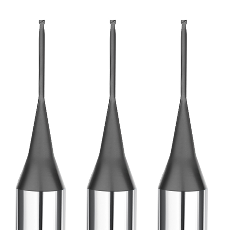
Comprehensive Process System Optimization: A Cost-Reduction and Quality-Enhancement Strategy with China Graphite End Mill Tooling
After analyzing surface defects, wear mechanisms, and 3D toolpaths, we must remember that a cutter never works in isolation. It is simply the final link in the machine tool chain. Over the years, we have seen many shops adopt a high-grade china graphite end mill only to struggle with surface roughness because of poor holder concentricity, imbalance, or turbulent vacuum airflow.
Surface hazing, scoring, and corner chipping are often amplified symptoms of a weak link in the overall setup. The solution is not stacking up overpriced tooling, but systematically aligning spindle runout, holder rigidity, cut parameters, and dust evacuation. Fine-tuning these variables allows you to achieve consistent mirror finishes on EDM electrodes while keeping tooling costs under control.
Dynamic Balancing (G2.5) and Shrink-Fit Tool Holders: Eliminating Centrifugal Vibration in Graphite End Mills at High Speeds
If you run finishing passes between 20,000 and 40,000 RPM and notice faint, periodic ripple marks on vertical walls, check your tool holder balance first. At high rotational speeds, slight mass eccentricity creates centrifugal forces that cause graphite end mills to oscillate. Standard ER collets, with their multiple contact interfaces, struggle to hold dynamic runout under 0.003 mm over continuous shifts.
If you are fighting deflection or wall taper in deep pockets, switch to integral shrink-fit or hydraulic holders balanced to G2.5 at operating RPM. Keep tool overhang as short as possible to clear the part. The 360-degree clamping pressure and symmetrical body of shrink-fit holders dampen micro-vibrations, keeping the cutting edge tracking within a stable plane.
Machining Ultra-Fine-Grain Isostatic vs. Standard Graphite: Speed Adjustments and Vacuum Airflow for Your End Mill for Graphite
If you machine dense isostatic graphite (grain size < 5 µm) using feed data meant for coarse extruded stock, increase your surface speed while holding chip load to a tight, consistent window. Fine-grain graphite is harder and denser, but its brittle fracture produces micro-fine dust. Running your end mill for graphite at high surface footage shears these fine grains cleanly, producing a crisp, semi-gloss finish.
Do not overlook your dry vacuum setup. If you notice dust packing around the cut or fine scuffing on the floor of the part, adjust the angle between your air blast and vacuum nozzle to build a push-pull vortex. Clearing abrasive dust from the flutes in milliseconds prevents secondary flank rubbing and reduces heat buildup in deep slots.
When Standard Tools Fall Short in Deep, Narrow Slots: Ordering Custom Graphite End Mills from China
Standard off-the-shelf tools make geometric compromises to cover general jobs. If you are milling tall, thin ribs or deep-cavity undercuts and running into chatter from excess flute length, standard catalogs will only take you so far. Partnering directly with a manufacturing facility for custom graphite end mills is often the fastest way to resolve persistent deflection issues.
Specifying a tailored neck relief, a modified helix angle to redirect cutting forces, or a micro-corner radius allows you to clear deep features in a single setup without blend lines. If you are dealing with stubborn surface flaws, edge breakout, or rapid tool wear on your electrodes, sharing your part prints, parameters, and graphite grades with a specialist helps build a reliable machining solution.






