
Last month, while troubleshooting a mold setup for a German automotive tier-one supplier, their process engineer pointed out a 1.2379 (D2) hardened insert fresh off the VMC. The CAM calculation predicted a theoretical finish of Ra 0.4 µm, but profilometer traces on the 3D complex cavity revealed localized values exceeding Ra 1.6 µm. The steel surface showed distinct micro-waviness and subtle witness marks along the deep ribs, forcing the shop to waste four hours on manual polishing.
This is a recurring problem we see weekly when supporting machine shops across Europe and North America. When finishing alloy and tool steels, programmers often lean entirely on theoretical cusp formulas built into CAM software. However, these basic formulas completely ignore tool deflection, workpiece spring-back, dynamic spindle runout, and the critical zero-speed dead zone at the cutter tip.
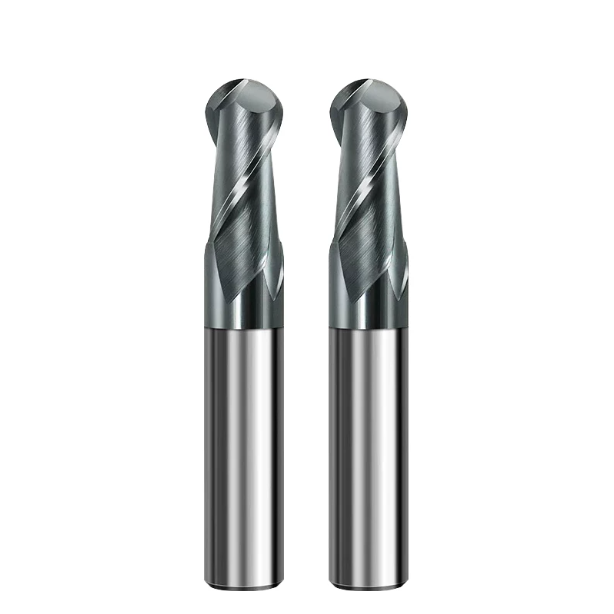
Achieving a uniform, premium satin or semi-mirror finish on steel demands matching your stepover strategy to heat-treated hardness, cutting depth, and machine rigidity. Whether you are running a standard ball milling cutter for cutting steel on 3D contours or switching to an hrc65 ball nose milling cutter for hardened tool steel, precise stepover adjustments dictate your final surface quality and tool life. Do you often find visible scallop marks on your steel parts even after dropping the stepover below 0.05 mm?
Balancing Stepover and Cusps on the Shop Floor: Maximizing Surface Quality When Milling Steel with Ball-Nose Cutters
When finishing tool steel on the shop floor, many machinists fall into a common trap: if the surface finish is poor, they simply shrink the stepover. In our manufacturing and field tests, blindly cutting stepover values often ruins the finish. When radial cut width drops below a critical threshold, the cutting edge stops shearing cleanly and starts burnishing the steel, generating friction heat that glazes the surface.
To achieve clean shearing, you need a balanced sweet spot between machine stiffness, tool cutting force, and chip formation. When setting up a premium ball milling cutter for cutting steel for 3D profiling, we maintain a radial stepover between 4% and 8% of the effective cutting diameter. Paired with a steady feed per tooth, this range pulls micro-chips cleanly away from the cut instead of rubbing against the steel.
The Gap Between Theoretical Calculations and Actual Steel Machining: Why the Same Stepover Fails to Yield the Expected Ra
During a recent trial at an automotive die facility in Michigan, a client ran an R3 ball nose cutter on H13 steel at a theoretical 0.08 mm stepover to target Ra 0.35 μm. The profilometer showed Ra 1.1 μm with noticeable surface ripple. CAM software assumes both tool and workpiece are 100% rigid. In reality, a modest 3 to 5 μm of tool deflection combined with steel elasticity ruins the calculated cusp profile.
When theoretical CAM numbers fail to produce the expected Ra on your machine, do not assume the cutting edge is dull. Look closely at dynamic radial deflection and the elastic spring-back of the alloy. Bumping up cutting speed while trimming the programmed stepover by 10% to 15% stabilizes tool pressure and yields a significantly cleaner surface finish than rigid textbook formulas.
Avoiding “Zero Cutting Speed” at the Center: Optimizing Tool Tilt and Step-over for 3D Steel Surfaces
When profiling flat or shallow-angle steel surfaces, the biggest obstacle is the center dead spot of the ball nose. Plunging vertically puts the center of the ball in contact with the stock, where cutting speed drops to zero. The cutting edge cannot shear the steel here; it simply tears and plastically displaces the material, leaving behind a dull center stripe and micro-burrs along stepover boundaries.
When programming multi-axis toolpaths, we always enforce a 10° to 15° lead or tilt angle to pull the contact zone away from the center. On standard 3-axis mills, adjust the toolpath direction so the side radius engages the cut. Tilting a ball end mill cutter keeps the cutting velocity high across the engagement zone, letting you run a slightly wider stepover while producing a far cleaner, burr-free surface.
From Semi-Finishing to Mirror-Like Finishing: The Direct Impact of Finishing Allowance on Step-Over Performance Across Cutter Types
Machinists often blame finishing tools for heavy scallop marks, but the real culprit is usually an uneven semi-finishing pass. When shifting across different milling cutter types—like roughing with a bull-nose end mill and finishing with a ball nose—inconsistent stock allowance leaves heavy steps on the wall. Sweeping across irregular stock causes cutting force spikes that deflect the tool tip, creating visible surface gouges.
We recommend leaving a constant, uniform stock allowance of 0.03 to 0.05 mm across the entire profile before running the final pass. Keeping stock thickness uniform ensures steady tool deflection and chip load at every stepover pass. This strict stock control keeps cutting pressure predictable and delivers a pristine, uniform finish across the entire 3D steel component.
Mastering Curved Surfaces on Hardened Steel: Step-Over and Surface Finish Control for HRC55 and HRC65 Cutters
When hard milling tool steels, a common headache is the rapid degradation of surface finish caused by accelerated edge wear. Extreme cutting zone temperatures and shear stresses subject the tool to severe micro-abrasion and thermal shocks. Setting the wrong stepover worsens this issue, causing the cutting edge to rub against the hardened surface, triggering flank chipping and coating delamination.
To machine hardened steel cleanly, tailor your stepover to the specific workpiece hardness range. Striking the right balance between cutting forces and thermal dissipation is crucial. Using a dedicated hrc55 ball nose milling cutter alongside ultra-hard tooling allows you to apply differentiated micro-feed strategies, preserving tool life and significantly cutting down manual polishing hours.
Finishing Pre-Hardened Mold Steel (P20/NAK80): Balancing Stepover and Tool Life for HRC55 Cutters
During an on-site trial for an automotive lighting mold client, operators dropped their stepover to 0.02 mm on 38–42 HRC pre-hardened steel to chase a mirror finish. The cutting edge wore flat before finishing half the cavity, leaving burnished, yellowish score marks. For ductile, medium-hardness steel, setting radial stepover (ae) to 5%–8% of cutter diameter is the ideal sweet spot.
A moderate stepover produces crisp micro-chips that carry cutting heat away from the part surface. Running an hrc55 ball nose milling cutter with tough sub-micron carbide and high-pressure air blast stabilizes cutting forces. Maintaining an ae of 5%–8% of tool diameter (D) generates a clean satin texture, reducing subsequent bench polishing time by nearly 40%.
Finishing Heat-Treated Steel (D2/SKD11/H13): High-Rigidity Micro-Stepovers with HRC65 Cutters
When material hardness hits 58–62 HRC or higher, standard milling rules no longer apply. Finishing high-alloy tool steels requires avoiding thermal micro-cracks and brittle recast white layers caused by excessive friction. Practical data from our stamping die projects shows the process must follow three rules: shallow axial cuts (ap ≤0.05 mm), fine stepovers, and high-speed climb milling.
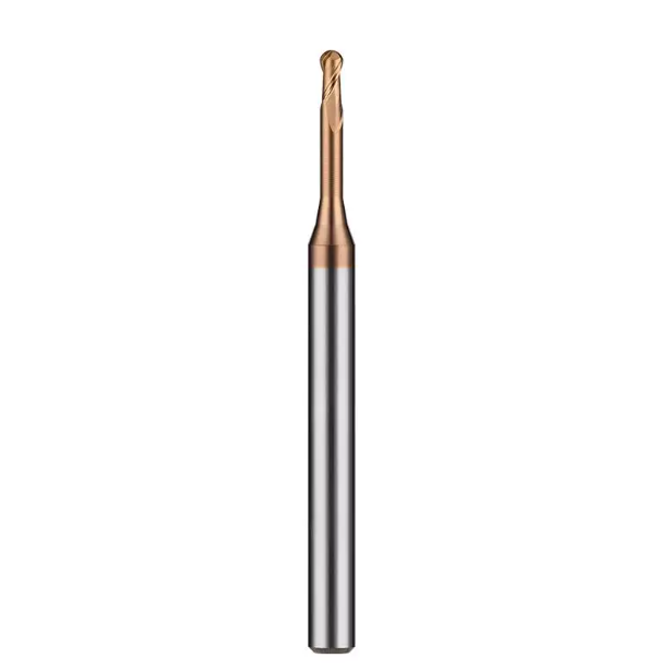
For these extreme conditions, we use an hrc65 ball nose milling cutter engineered for ultra-hard tool steels. Built with high-silicon nanocomposite coatings heat-resistant up to 1100°C, it micro-shears thin layers of hard metal at a 0.02–0.04 mm stepover. Coupled with balanced toolholders and dry air cooling, it produces a flat, pit-free matte finish without thermal damage.

Corner Cleaning in Deep Cavities and Narrow Slots: Chatter Suppression with 2-Flute Long-Neck Cutters
Finishing deep ribs, deep-hole corners, and narrow pockets is one of the toughest moldmaking tasks. As cavity depth increases, extended tool overhang causes shank bending stiffness to drop exponentially. In this low-rigidity setup, minor cutting load spikes trigger high-frequency chatter, leaving ugly fish-scale chatter marks across cavity walls and floors.
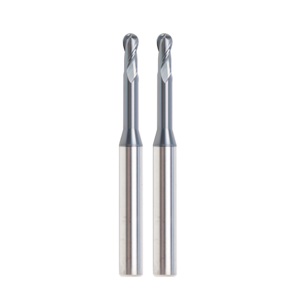
Many operators drop spindle speed to fight chatter, but that often worsens tool deflection. Our core strategy focuses on keeping cutting loads light and uniform through toolpath and feed adjustments. Selecting a rigid, tapered 2 flutes ball nose long neck milling cutter paired with fine radial steps eliminates resonance and rescues your surface finish.
Deflection Compensation for Overhangs Exceeding 5D: Stepover Reduction for Long-Neck Tools
We resolved a severe rib-sidewall mismatch for an injection mold maker running an overhang ratio of 6 times the diameter (6D). Standard 5%–8% stepovers caused the tool shank to bend on entry and gouge on exit spring-back. We corrected this by trimming radial stepover to 2%–3% of tool diameter while bumping surface speed with a light chip load.
In tight corners where tool engagement spikes, avoid direct linear plunges and program smooth trochoidal or radius corner roll-ins instead. Combining a fine stepover with a rigid 2 flutes ball nose long neck milling cutter lowers instantaneous torque spikes. This minimizes bending deflection and yields seamless, chatter-free transitions at the bottom of deep pockets.
Balancing Chip Clearance and Rigidity: Why 2-Flute Long-Neck Ball Mills Produce Smoother Sidewalls
Deep-cavity finishing requires balancing chip evacuation space against shank bending rigidity. Multi-flute end mills offer higher core stiffness, but their narrow flutes trap chips in deep, enclosed steel slots. If hot chips are not cleared instantly, the tool recuts them, causing micro-chipping along the cutting edge and scratching the cavity sidewalls.
Two-flute geometries resolve this by providing deep chip pockets and optimized core-to-diameter ratios. A well-designed 2 flutes ball nose long neck milling cutter gives high-pressure air blasts or MQL fluids direct access to the cutting zone. Blowing chips away instantly prevents chip packing and gouging, ensuring flat, flawless sidewalls on high-aspect-ratio features.

Machine Tools, Tool Holders, and Batch Tolerances: Shop-Floor Control to Prevent Surface Marks
Machinists often blame poor surface finishes entirely on CAM software and stepover settings, overlooking hardware errors in the machining chain. When targeting micron-level roughness on 3D contours, tiny deviations quickly compound. Spindle thermal growth, toolholder micro-runout, and loose tool tolerances can easily ruin an otherwise perfect toolpath.
To ensure consistent surface quality across long machining cycles, you must eliminate these systemic errors. If the tool tip runs out dynamically, micro-stepovers create uneven, wavy cusps instead of smooth surfaces. Using high-precision toolholders and verifying that your wholesale ball nose end mill batches maintain tight manufacturing tolerances is the true baseline for flawless surface finishes.
The Critical Impact of Radial Runout on Micro-Step Machining: A Clamping Standard of Within 0.003 mm
While troubleshooting visible banding on a client’s large steel mold, we noticed alternating dark and light stripes every few centimeters. A dial test indicator at the spindle nose showed 0.012 mm of radial runout on their standard ER collet. At a fine 0.05 mm stepover, this runout meant only one flute was cutting while the second flute merely rubbed, creating severe cyclic vibration marks.
For precision micro-step finishing on tool steel, total dynamic runout at the tool tip must stay under 0.003 mm. Standard spring collets rarely maintain this precision under load, making high-rigidity shrink-fit or hydraulic chucks a much better choice. When both flutes engage with equal chip load, your ball end mill cutter generates a crisp, uniform toolpath with consistent cutting depth across the whole profile.
Factory-Direct Consistency: Controlling Edge Tolerances for Wholesale Ball Nose End Mills in Mass Production
Mid-cycle tool swaps are unavoidable when finish-milling large die cavities or running lights-out mold production. A common shop headache is finding a 5 to 10 μm witness step right where a fresh tool took over. This mismatch happens when cutting tools lack strict ball profile accuracy and radius consistency, creating uneven curvature steps that tool presetters cannot fully compensate for.
From a manufacturing standpoint, premium wholesale ball nose end mill products must be ground on multi-axis CNC grinders with in-process laser probing to hold ball profile tolerances within ±0.005 mm. Paired with consistent micro-edge honing and uniform PVD coatings, batch-to-batch consistency allows seamless tool transitions on hardened steel without leaving visible blend lines or requiring extra bench polishing.






