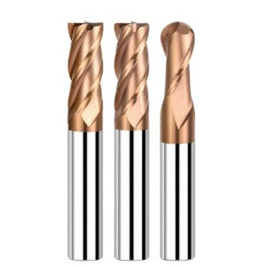
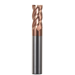
Last month, a mold shop in Bavaria sent us an urgent trouble ticket. They were milling 56 HRC D2 (1.2379) stamping dies on a 5-axis machining center. The corner fillets and deep cavity walls kept failing inspection, and their deadlines were slipping fast.
Photos from their shop microscope were telling. The tools were not snapping in half. Instead, each carbide bull nose end mill showed severe micro-chipping right along the corner radius in under forty minutes. The coating peeled, chatter kicked in, and the workpiece finish was ruined.
We see this exact failure mode dozens of times every year. Many machinists blame hard material or bad tool batches. But when you inspect spent cutters under an electron microscope, the truth becomes obvious: premature failure on a bull nose end mill for hardened steel never starts on the OD flute or bottom face. It always hits the critical radius transition first.
At 50 to 62 HRC, shear forces spike while plastic deformation drops to near zero. Friction concentrates intense heat and pressure onto a tiny contact patch. If your shop runs catalog feed rates without adjusting for effective cutting diameter, or runs a long neck bull nose end mill with too much stick-out, you do not wear out the cutter—you shatter it.
As frontline solid carbide end mills manufacturers, we know that micro-grain substrates and negative rakes must match CAM toolpaths precisely. Selecting the right bull nose end mill sizes dictates your deflection limits. Meanwhile, running aggressive cuts without calculating bull nose end mill feed and speeds around chip thinning burns expensive spindle time.
Hard milling is never about simply dropping your RPM and hoping for the best. If your floor struggles with chipped tool corners, wall taper, and wild tool life swings, ask yourself this: Did your failure start before the cut, right when you calculated your effective surface footage?
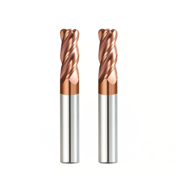
Why Does a Bull Nose End Mill Always Fail First at the Corner Radius in 50–62 HRC Steels?
When machinists show us broken cutters, over 80% of the damage sits squarely on that tiny corner radius. The end face looks fine, the peripheral flutes are intact, but the radius is chipped or burnt black. Many blame hard spots in the stock. In reality, the corner of a bull nose end mill endures a complex triaxial stress field. Surface speed transitions from peak values at the outer diameter to near-zero at center, concentrating thermal gradients directly on the corner.
Dynamic cutting monitoring shows that hardened steel yields a narrow shear zone, leaving no time for chips to carry away heat. Over 70% of cutting heat traps directly in the contact arc. While a corner radius removes the weak sharp point of a square tool, it anchors the heaviest thermal-mechanical loads on that curve. Without balancing axial cut depth with radial corner load, thermal cracking and wear accelerate at this junction.
Micro-Chipping and Flank Wear: Real-World Fatigue Under the Microscope
When inspecting worn carbide bull nose end mill tools from D2 or H13 setups under 100x magnification, we rarely see simple abrasive wear. Instead, we see dense, shell-like micro-fractures along the tungsten carbide grain boundaries. This micro-chipping occurs when unit pressure exceeds the substrate’s shear limit. Once micro-fractures begin, flank wear widens uncontrollably, triggering rapid thermal runout and catastrophic tool failure.
The most dangerous moment occurs during straight plunge cuts or sharp corner entries, where entry shock can spike cutting resistance threefold. Hardened steels provide zero plastic cushion. The cutting edge strikes the material like a miniature hammer on every pass. If tool paths lack smooth arc lead-ins, shear forces exceed the transverse rupture strength of the carbide. Grains shear away instantly, inducing severe machine chatter and ruined parts.
Thermal Shock and Coating Delamination: The Limits of AlTiN and Si-Based Coatings Under Dry Air Blasts
The most common error we encounter in Western machine shops is flooding 55+ HRC cuts with high-pressure coolant. Coolant seems helpful because it clears smoke, but the cutting zone quickly exceeds 1,000°C. Flooding causes severe thermal cycling as teeth alternate between glowing engagement and sudden cooling. On many a bull nose end mill for hardened steel, we find comb-like thermal cracks under the microscope, which slice through the coating and delaminate the substrate.
For high-hardness milling, we routinely advise switching off liquid coolant in favor of a targeted, high-pressure dry air blast. Dry cutting allows AlTiN and AlCrN coatings to form dense aluminum oxide barriers that resist extreme heat. Still, realistic tradeoffs apply: if the manufacturer fails to prep the micro-substrate properly, even premium coatings peel under shear stress. Achieving predictable tool life requires balancing proper edge prep, strong coating adhesion, and continuous air blast chip evacuation.

Substrate and Geometric Optimization of Carbide Bull Nose End Mills for Hardened Steel
Process engineers often show us prints and ask: “At 55–60 HRC, shouldn’t the cutter just be as hard as possible?” Our short answer is no. Grinding cutting tools on 5-axis CNC machines taught us that hard milling demands balance. If you focus solely on Rockwell hardness while ignoring the edge’s load-bearing ability, the tool will shatter within five minutes.
When we inspect a premium carbide bull nose end mill, its real edge lies in microscopic modifications. We control carbide crystal packing and grind seamless tangency blends between the radius and flutes. Any microscopic stress riser will ruin the cutter in hard steel. We rebuild microscopic geometries to create an impact-resistant frame right at the corner.
High Cobalt or Low Cobalt? Trade-offs in Substrate Selection for Solid Carbide End Mill Manufacturers
As solid carbide end mills manufacturers, customer feedback drove us to run countless destructive tests on raw rods. Machinists often assume low cobalt (6%–8%) is mandatory for hard steel. In practice, that recipe chips rapidly during interrupted cuts. We target 10%–12% cobalt with sub-micron 0.4–0.6 μm grain sizes, using the cobalt binder to absorb heavy shock.
Beyond the blank, edge prep determines whether the tool survives. Operators often tell us that sharper cuts better, but a razor edge chips like glass on 60 HRC stock. We run controlled brushing to produce a 15–20 μm drop-shape edge hone. This tiny hone distributes point loads deep into the carbide body and stops premature micro-flaking.
Negative Rake Angle and Thickened Core Design: The Foundation of Rigidity for Hard Milling
To prevent micro-deflection under heavy cutting forces, a bull nose end mill for hardened steel requires extreme core strength. When grinding these flutes, we increase the web thickness to 65%–70% of the total diameter. While this reduces flute gullet space, hardened steel yields fine, needle-like chips. Sacrificing chip clearance for massive radial rigidity eliminates sidewall taper.
We also grind a -6° to -10° negative rake to transform cutting forces. Positive rakes pull the edge into the cut, inviting chipping. A negative rake converts destructive tensile tension into pure compression, playing to carbide’s greatest strength. Paired with variable helix angles (35°/38°) and uneven fluting, this geometry breaks harmonics and protects the corner radius.

Machining Deep and Complex Cavities: Managing Overhang and Vibration in Long-Neck Bull-Nose End Mills
Deep ribs and slots in mold cavities present a tough choice. Short cutters lack reach, while standard long extensions squeal and drift off size. With wall clearances measuring mere microns, the slightest deflection ruins cavity verticality. Milling deep pockets is never a race for high speeds; it is a battle to tame dynamic tool deflection.
In our field tests, tool breakages rarely stemmed from defective carbide. Instead, programmers ran a long neck bull nose end mill like a stubby, rigid tool. When overhang reaches 5×D or 8×D, rigidity drops by a cubic factor. You must respect these mechanical limits. Using tapered neck transitions and smooth CAM paths keeps high-frequency vibration inside safe boundaries.
Relieved Neck Geometry and Length-to-Diameter Ratio: Strategies for Mitigating Drastic Rigidity Loss
Selecting the correct neck relief profile stops deep cavity sidewall rubbing. When grinding custom tools for clients, we always suggest a 1°–3° tapered neck over a straight undercut whenever draft angles allow it. Field data shows that even a slight taper increases bending resistance by nearly 30% at 6×D reach. This reinforcement limits wall taper caused by radial side load.
Still, programming cannot ignore real-world tool deflection. Never trust 3D CAD models blindly. Always measure tool stickout with an optical tool setter and apply negative radial stock offsets in your CAM software. When finishing deep hardened walls, using progressive step-downs and keeping your radial cut width ($A_e$) under 1%–2% of the cutter diameter guarantees precision.
Deep Rib Machining Analysis: Toolpath Strategies to Prevent “Bottom Rubbing” with Long-Neck Tools
The blind pocket bottom is where high-overhang tools fail first. Many shops plunge straight down or ramp aggressively into the cut. However, center surface speed on a carbide bull nose end mill drops close to zero. Plunging forces the dead center into the metal, causing severe rubbing and frictional heat over 1,000°C that anneals the edge. We always cap helical ramping between 1° and 1.5°.
Cornering toolpaths also require strict care. Direct 90-degree turns spike tool engagement from a few degrees up to 180 degrees instantly. This sudden load deflects slender tool necks and snaps the corner radius during the rebound. We tell operators to disable hard-stop corners and program smooth corner-rounding loops with feed deceleration to maintain steady cutting pressure.

Avoiding Chip Thinning and Friction: The Logic Behind Adjusting Feeds and Speeds for Bull-Nose End Mills
Many machine shops simply copy catalog speeds and feeds directly into their CAM setups. While that works for soft alloys, hard milling 50–60 HRC steels destroys tool tips instantly with those numbers. Hardened material has a tiny shear zone and poor thermal conductivity. The cutter must run within a strict window of surface speed and chip load.
Our field tests show that the contact diameter of a bull nose cutter changes continuously with depth. Ignoring effective diameter loss and chip thinning causes severe friction instead of real shearing. Optimizing your bull nose end mill feed and speeds is not about chasing high table feed rates. It is about ensuring every carbide grain cleanly shears stock rather than rubbing against a work-hardened surface.
Effective Diameter Conversion: Solving the Parameter Trap of “Rubbing to Death at Low Speeds vs. Burning to Death at High Speeds”
When finish-milling mold cavities, axial cut depth (Ap) is often smaller than the corner radius (R). Programmers routinely calculate RPM from the nominal tool diameter (D). However, the true contact diameter is often only a fraction of that size. This drops your actual surface footage so low that the honed edge rubs and burnishes, rapidly grinding the edge to death.
Conversely, hiking spindle speed without bumping chip load triggers the chip-thinning trap. The actual chip thickness drops well below the physical hone radius on the cutting edge. The cutter then skates over the work-hardened skin, generating thermal spikes that burn out the tip. On every carbide bull nose end mill, always recalculate spindle RPM using effective diameter and adjust feed per tooth upward to maintain a true chip cut.
Comparison of Cutting Parameters for Typical Hardened Materials: Trochoidal and Plunge Milling Data for H13 (52 HRC) and D2 (60 HRC)
A North American automotive die shop recently fought premature corner chipping on 52 HRC H13 and 60 HRC D2 dies. We overhauled their CAM toolpaths to run a High-Efficiency Milling (HEM) strategy with radial engagement (Ae) locked at 5%–10%. Switching from heavy conventional cuts to dynamic trochoidal motion stabilized tool loads and kept cutting temperatures steady.
When dialing in a bull nose end mill for hardened steel, we applied a counter-intuitive fix. We cut surface speed by 15% to stop thermal build-up and raised feed per tooth by 20% to beat chip thinning. This adjustment eliminated corner blackening and stopped premature thermal fatigue. Tool tip life jumped by nearly 50% across the entire mold cavity run.
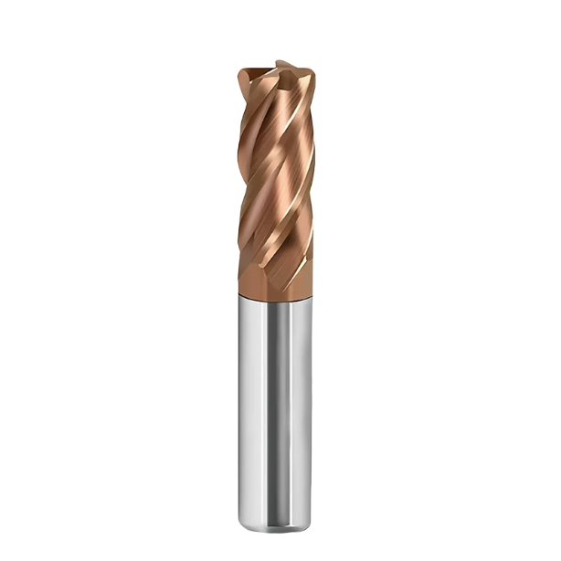
Matching Bull-Nose End Mill Sizes and Optimizing Step-over in Mold and Precision Part Machining
During cavity finishing, machinists often crank up spindle speeds while ignoring how diameter and corner radius interplay. Scallop height is strictly a geometric function of tool radius and stepover distance. Forcing a single tool size across every mold feature blows out cycle times. It also creates unbalanced cutting forces that deflect machine guideways and tool tips.
Choosing the right bull nose end mill sizes creates a workable balance between scallop height, cutting load, and tool life. Forcing small corner radii into heavy cuts or using oversized diameters in tight corners spikes tool pressure. Matching tool diameter and corner radius to the cavity depth and wall curvature keeps tool deflection low while holding micron-level surface finishes.
Mechanical Balance Between Standard Sizes (Metric & Imperial) and Corner Radius Ratios
We balance metric and imperial geometry continuously when setting up customer tool cribs. On a 1/4″ or 6mm cutter, an R0.5mm (0.020″) radius follows tight profiles well, but the supporting carbide remains thin and prone to chipping. Bumping to an R1.0mm or R1.5mm radius doubles corner strength, though it narrows the bottom flat. On 10mm and 12mm tools, an R1.0mm to R2.0mm radius hits the sweet spot for rigidity under heavy roughing loads.
Beware of assuming larger radii are always better. On thin-walled hardened steel over 55 HRC, oversized radii lengthen the contact arc. This shifts downward axial forces into aggressive lateral side loads. Our shop tests prove that excessive radial push causes wall flex and chatter. This leaves mold walls with severe concave errors where they should be dead straight.
Balancing Stepover and Scallop Height in 3D Surface Finishing
On open, contoured surfaces, we regularly replace standard ball-nose cutters with a high-grade carbide bull nose end mill. A ball cutter’s dead center cuts at near-zero surface speed, leaving torn, smudged finishes. A bull nose cutter has a true flat bottom. This allows programmers to expand radial stepover by 1.5 to 2 times for the exact same scallop height, cutting finishing run times by nearly 30%.
This stepover strategy also protects the next tool in line. Ball cutters leave jagged, uneven cusps along cavity walls and corners. When a smaller pencil-finishing tool hits those cusps, sudden stock spikes cause tool digging or snapping. A bull nose tool leaves clean, uniform residual stock. That consistent baseline protects subsequent detailing cutters from fatal shock loads.
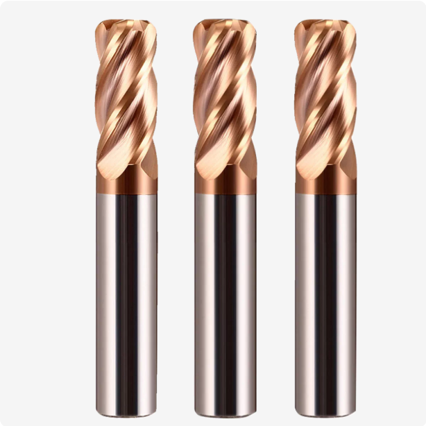
Shop-Floor Implementation: How We Helped European and American Clients Extend Bull-Nose End Mill Life by Over 40% When Machining Hardened Steel
Machining hardened steel demands a total system approach. Tool life is not about isolated tweaks; it connects geometry, machine dynamics, and thermal controls. In our field visits, early failure on a bull nose end mill for hardened steel rarely comes down to bad carbide alone. Substandard holders and loose tool-inspection habits are usually the real culprits.
We turned these field hard-knocks into a working shop-floor checklist. Controlling spindle runout, dynamic tool balance, holder clamping force, and wear limits pays off immediately. Addressing every micron-level variable adds up. Your tools will last longer, and parts will come off the table with pristine finishes.
Tool Holder Runout Control and Clamping Rigidity: The Amplification Effect of Micron-Level Runout
On soft materials, 0.010mm of runout might pass inspection, but hard steels punish runout severely. Our field tests show that when standard ER collets exceed 0.005mm Total Indicated Runout (TIR) at the tool tip, tool life plummets. At micro-feed rates, runout forces one tooth to take 100% of the shock load while the others skip. That overloaded tooth chips, ruining the cutter instantly.
We advise replacing standard mechanical collets with high-rigidity shrink-fit or hydraulic tool holders, capping tip runout under 0.003mm. If older spindles lack dynamic balance or stiffness, take a parameter retreat. Dial back spindle RPM by 10%–15% and trim radial cut width (Ae). Shifting away from resonant harmonic frequencies stabilizes cutting conditions before you push for speed.
Factory Inspection by Solid Carbide End Mill Manufacturers and On-Site Determination of End-of-Life Wear
As global solid carbide end mills manufacturers, our factory inspection standards remain unforgiving. We do not just inspect basic outer diameters. We use 5-axis optical comparators to hold the corner radius profile tolerance within ±0.005mm. Seamless tangency transitions between the radius, bottom face, and side flutes eliminate steps. This level of grinding precision guarantees repeatable CNC performance on the shop floor.
Operators must also watch for the correct wear limits and stop running tools until they break. We train machinists to inspect flank wear with hand-held pocket microscopes, pulling tools the moment wear reaches VB = 0.15 mm. If you battle erratic tool life, wall taper, or broken flutes in hard tool steel, audit your actual runout, contact depth, and tool-change criteria right away.
Every setup presents unique challenges depending on machine stiffness, workholding rigidity, and steel alloy lots. No single catalog chart solves every challenge. If you are struggling with a difficult die cavity, long-reach wall deflection, or inconsistent tool wear on hardened stock, let’s talk. We can examine your part blueprints, analyze your tool overhang ratios, and build a predictable, cost-effective hard milling strategy together.