
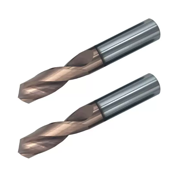
Last month, our engineering team resolved a severe production bottleneck at a German Tier-1 automotive plant. Several horizontal machining centers were completely stalled while running 42CrMo4 (AISI 4140) hydraulic valve blocks. The job involved blind holes with a 6.0 mm diameter at an 8D aspect ratio. The shop had loaded standard-flute carbide drill bits for steel and relied on a G83 peck-drilling cycle to clear chips.
Cycle times exceeded two minutes per hole. Worse, beyond 5D depth, hardened chips began packing tightly inside the narrow flutes. The tools vibrated violently, squealed, and chipped out every 40 holes, sending scrap rates through the roof. This is a scenario we encounter regularly across machine shops running generic steel drill bits. We took the machine off G83, switched to our parabolic-flute through-coolant drills, and applied a continuous feed pass at 40 bar coolant pressure.
Cycle time dropped by 58%, and the tool drilled over 350 holes with only light, uniform flank wear. Why do conventional metal drill bits for steel suffer severe wandering and torsional failure once you pass 5D? And how does parabolic flute geometry solve the trade-off between web rigidity and chip evacuation to rank among the best bits for drilling steel? If you are battling erratic spindle loads and broken drills on your floor, let’s examine what happens along the cutting flute.
From Chip Jamming to Single-Pass Drilling: Why Do Standard Spiral Flutes Break Frequently in Deep-Hole Steel Machining?
During on-site audits, we routinely watch spindle load meters spike the moment a drill passes the 4D mark. Standard spiral flutes work well in shallow bores, but friction rises exponentially in deep cavities. When stringy chips fail to curl into tight “C” shapes at the cut zone, they stretch into ribbons. These ribbons wedge against the flute walls, choke the evacuation path, and snap the tool.
Eliminating this failure mode requires ditching the habit of pecking to clear debris. Through hundreds of destructive cutting trials, we found the real culprit: restrictive flute cross-sections. You must reduce the contact area between the chip and the flute wall while improving fluid flow down the hole. For long cycle runs, selecting application-matched drill bits for steel with optimized flute relief is the only proven way to run single-pass drilling without tool failure.
Real-World Challenges for European and American Clients: A Surge in Chip Evacuation Resistance with Standard Steel Drill Bits at 5D–8D Depths
When evaluating field data from heavy-equipment clients cutting 4340 and 8620 alloys, a distinct failure pattern emerges past 4D depth. At that depth, external fluid pressure cannot penetrate the bottom of the bore. Hot chips undergo severe secondary shearing against the hole wall, leaving heavy galling along the ID finish.
This issue stems directly from the tight cross-section of standard-design steel drill bits. Their deep “V” profiles offer minimal clearance, forcing hot swarf to drag against the flute surfaces under heavy axial thrust. Operators usually drop their feed rates by 30% to 50% to baby the tool. Unfortunately, that underfeeding causes rubbing, work-hardens the alloy base, and destroys the cutting edge even faster.
Analyzing Parabolic Flute Geometry: Why It’s the Best Choice for Deep-Hole Drilling in Alloy Steel
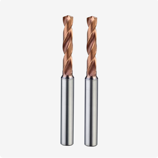
To quantify how geometry affects swarf flow, we ground multiple flute profiles on our 5-axis tool grinders and tested them on a rigid horizontal machining center. Standard flutes trap chips over an engagement arc wider than 120 degrees. In contrast, a parabolic curve opens the flute bed wide. The curled chip contacts the tool body at minimal points, sliding out with almost zero frictional drag.
This open profile also clears a dedicated highway for high-pressure through-spindle coolant. At 30 to 50 bar, cutting fluid floods the chisel edge, creates continuous hydrodynamic lift, and blasts chips out of the hole instantly. By keeping cutting zones cool and flutes clear, these tools consistently prove to be the best bits for drilling steel across medium-carbon, alloy, and tool steel families.
Balancing Rigidity and Chip Evacuation: How Optimized Flute Design Prevents Torsional Breakage in Deep-Hole Drilling of Steel
Machinists often ask a logical question: if you widen the flute to clear more chips, don’t you weaken the drill core? In early development, simply deepening the flutes drastically reduced torsional stiffness. The drills chattered on entry, rubbed their margins raw, and sheared off near the shank when hitting hard spots in cast or forged stock.
Parabolic engineering solves this trade-off through non-linear curvature. It increases chip clearance by 20% to 30% while maintaining a heavy, reinforced web core. This geometry gives high-performance metal drill bits for steel the structural backbone to resist high feed thrust, while preventing the chip-packing that snaps standard tooling in deep bores.
Real-World Application Analysis: How Carbide Drill Bits for Steel Eliminate the Need for Peck Drilling via Parabolic Flute Geometry
Most machine shops treat the G83 peck cycle as an automatic reflex for 5D to 8D depths. However, full retractions compromise tool life through severe thermal cycling and mechanical shock. Each exit and re-entry batters the cutting edge against the hole bottom, inducing micro-cracks along the chisel line.
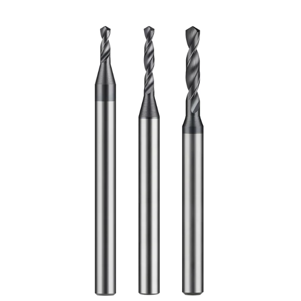
Switching to a parabolic flute profile fundamentally changes internal chip flow. The expanded cross-section evacuates chips continuously, rendering reciprocating pecks obsolete under stable coolant flow. Running solid carbide drill bits for steel with this geometry prevents swarf re-shearing and eliminates air-cutting cycles on high-volume runs.
From Frequent G83 Retraction to Single-Pass Drilling: Parabolic Flute Geometry Cuts Cycle Time by 40% for 4140 and 316 Steel Components
We re-engineered a valve block line for a North American fluid power shop running 7D deep bores in AISI 4140 and 316 stainless. The shop was running G83 with 1D peck steps. The spindle retract motions ate up nearly half of the total cycle time, bottlenecking the entire horizontal cell.
We replaced their tooling with our parabolic through-coolant steel drill bits and switched to an uninterrupted drilling cycle with a boosted feed rate. The broad flutes evacuated chips cleanly without packing. Cycle time per bore plummeted by 40%, while eliminating work-hardened transition rings and improving internal surface finish to a steady Ra 1.6.
Coolant Hydrodynamics in Practice: Internal Cooling Paired with Parabolic Flute Chip Evacuation to Prevent Micro-cracks Caused by Cutting Heat
Tiny transverse fractures and thermal spalling along the primary cutting lip are rarely caused by insufficient carbide hardness. Instead, they stem from thermal shock and intermittent cooling starvation. In standard narrow flutes, outward-surging hot chips block coolant flow, leaving the drill tip running in an abusive, semi-dry zone.
The parabolic curve creates an open exhaust duct for through-spindle coolant. Operating at 20 to 40 bar, the cutting fluid blasts directly across the cutting edge, forming a continuous hydrodynamic boundary layer. By outfitting the spindle with dedicated metal drill bits for steel, fluid flushes chips out instantly and shields the PVD coating from thermal fatigue.
140° Point Angle and Split Point Geometry: Eliminating Deep-Hole Deviation and Bell-Mouth Defects
Hole wander, drift, and bell-mouth entries are rarely caused by margin guide wear alone. In deep holes, entry centering is the real culprit. Standard 118° point angles with thick chisel webs generate excessive axial thrust, causing the drill tip to skate before full engagement—a flaw amplified across long aspect ratios.
We pair a 140° point angle with a precision S-shaped split-point grind, reducing axial thrust by over 30%. This profile delivers immediate self-centering upon contact, eliminating the need for spot drills in most production setups. For true hole perpendicularity and runout under 0.02 mm, this centering design makes these tools the best bits for drilling steel.
Mastering Quenched & Tempered Steel and Hardened Mold Steels: The Limits of Parabolic Deep-Hole Drilling with HRC55 Carbide Bits
Drilling deep cavities into hardened die materials like SKD11, NAK80, or H13 (HRC 50+) tests tool geometry to its physical limits. Elevated shear resistance generates extreme cutting zone temperatures. Without sufficient substrate toughness and reliable evacuation, the drill tip faces instantaneous plastic deformation or gross edge chipping.
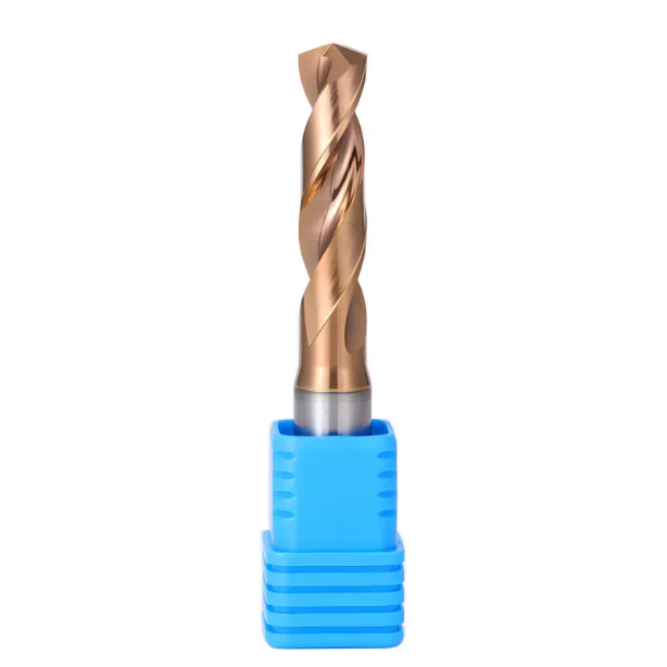
Chasing maximum hardness alone is a common mistake on hard steels. True process reliability requires blending a parabolic flute’s heavy web core with hrc55 carbide drill bits ground from sub-micron substrates. Balancing core cross-section, high-heat coatings, and free-flowing chip channels creates a predictable wear pattern instead of sudden catastrophic tool failure.
Addressing Work Hardening in Deep-Hole Drilling of HRC 50–55 Mold Steel: High-Rigidity Flute Geometry and Feed Control for HRC 55 Carbide Drills
While optimizing mold ejector pin holes, we frequently catch operators backing feed rates down to 0.02 mm/rev out of caution. Underfeeding is fatal in hardened alloys. The cutting edge merely rubs across the work-hardened skin from the previous pass, spiking cutting temperatures and dulling the tool within seconds.
A parabolic flute retains a beefy web core, delivering the torsion resistance needed to maintain positive cutting pressure. When running dedicated hrc55 carbide drill bits, we maintain feeds between 0.05 and 0.09 mm/rev. This keeps the cutting edge digging into fresh virgin stock beneath the hard glaze, slashing frictional heat.
Nano-Multilayer AlCrN Coating and Passivation: Suppressing Crater Wear When Machining Ultra-Hard Steel
During deep-hole drilling of hardened mold steels, intense frictional heat on the rake face drives severe diffusion wear. Superheated chips scouring the cutting face strip weak coatings, carving deep craters that undermine the cutting edge. Thicker coatings do not solve this; they round the edge and invite premature spalling.
We resolve this by applying an engineered edge prep (5 to 12 µm hone) to remove micro-serrations, followed by an AlCrN nano-composite coating stable past 1050°C. For heavy-duty drill bits for steel, this dense ceramic layer resists cratering and protects the carbide substrate through extreme thermal duty cycles.
On-Site Troubleshooting: Adjusting Cutting Speed in Real-Time Based on Chip Morphology (“C”-shaped vs. Long, Curly Chips)
Stopping the cycle to bore-gage holes is secondary; your chip pile is the fastest real-time diagnostic tool. In alloy steels, tightly curled “C” or “6” shaped chips with an even straw or purple temper color show ideal thermal shear balance. Under these conditions, the parabolic flutes are clearing chips at peak performance.
Conversely, continuous stringers or ribbon chips mean cutting speed is too high relative to your feed, failing to break the steel’s ductility. Dark, burned chips with burred tears indicate you are exceeding coating thermal thresholds or micro-chipping the lip. Drop surface footage by 15% to 20% immediately and check coolant delivery to safeguard your carbide drill bits for steel.
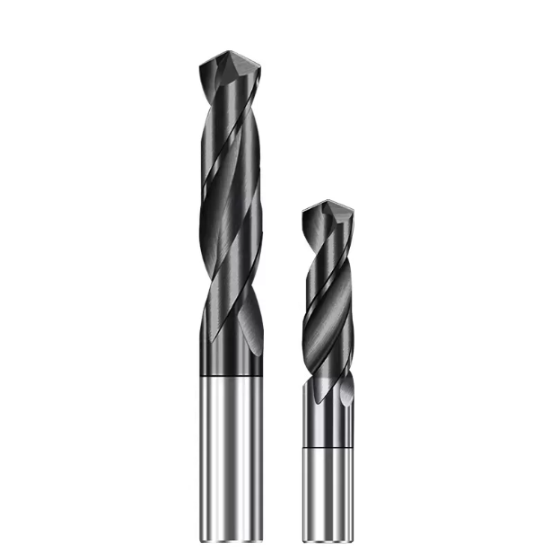
Non-standard Solutions When Standard Tools Fall Short: When to Switch to Custom Drill Bits?
Standard catalog tooling handles common hole patterns easily. However, when you encounter multi-stepped profiles, high aspect ratios, or tight bore tolerances, off-the-shelf drills quickly bottleneck your throughput. Shops frequently try chaining three or four standard tools together to produce one complex cavity. That practice piles up tool-changer cycle dwell, introduces blend-step marks, and amplifies runout errors across operations.
When standard flute geometries hit mechanical limits in chip clearance or balance, grinding purpose-built step angles becomes essential. Investing in engineered custom drill bits is not a cost penalty. For high-volume production or critical aerospace components, matching the drill geometry to your specific part geometry lowers your true cost-per-hole significantly.
Complex Holes and High Length-to-Diameter Ratios (10D–20D): Custom Stepped-Flute Designs for Steel
We recently re-engineered a transmission line machining 15D stepped cavities in forged alloy. The original process sequenced three standard drills to rough the pilot, size the bore, and finish a sealing chamfer. Hot chips from the second tool fell into the bore and scored the finished seal, while tool-changer stack-up caused recurring CMM rejections.
Our SAMHO engineering team resolved this by grinding dedicated custom drill bits for steel on 5-axis CNC grinders, integrating the parabolic primary flute with a stepped chamfer lip into a single tool. This single-shot approach eliminated tool-change tolerances and blend steps. By profiling a smooth transition along the secondary step, we eliminated swarf vortexing and kept the evacuation channel completely clear from 15D deep.
Tailored Solutions for Specialty Heat-Resistant Alloys and Aerospace Structural Steels: Customizing Drill Point Chamfers, Margin Widths, and Internal Coolant Channel Configurations
Running difficult materials like 17-4PH, Inconel, or 300M ultra-high-strength steel exposes standard margin flaws. Dual-margin drills generate excessive friction and galling, while single-margin tools chatter during cross-hole interruptions. For severe work-hardening alloys, back-taper per inch, secondary relief angles, and margin land widths require micron-level adjustments.
Internal coolant channel size and exit helix angles must also be calibrated against fluid delivery volume. Oversized coolant holes weaken the tool’s core stiffness, while undersized orifices drop fluid velocity below the threshold needed to flush stringy swarf. When manufacturing specialized metal drill bits for steel, we narrow margin contact patches and angle internal fluid ports directly at the shear shear zone to maximize cooling efficiency.
Engineer-to-Engineer Prototype Validation: Rapid Custom Delivery Based on Machine Rigidity, Spindle Runout, and Toolholder Clamping Data
Many tool vendors build custom profiles strictly from part prints without considering the machine platform. Before grinding blanks, our engineering team audits your physical cutting conditions. We verify operating through-spindle coolant pressure in bar, holder interfaces (hydraulic vs. shrink-fit), measured dynamic runout at the nose, and fixture rigidity over unsupported spans.
Capturing these shop-floor variables allows us to tailor web taper rates and micro-honed k-factors precisely in our CAD/CAM software. When these application-engineered best bits for drilling steel reach your spindle for first-article tryouts, they run immediately at targeted feeds and speeds without costly trial-and-error regrinding loops.
Machine-Side Clamping and On-Site Setup Standards for Extending Deep-Hole Tool Life
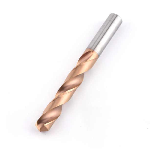
Even the most advanced parabolic geometry and premium sub-micron carbide substrate cannot overcome a poor machining setup. The physical interface—spindle condition, toolholder selection, and overhang ratio—determines whether you extract 100% of a tool’s performance or break it on entry. During on-site failure audits, we find premature chipping is rarely a tool defect; it almost always tracks back to excessive runout or weak toolholder clamping.
Consistent tool performance requires a rigid connection between the spindle taper, holder, and cutting edge. Even dynamically balanced carbide drill bits for steel will chatter if loaded into worn chucks. Microscopic wobbling during hole entry multiplies along the drill body, causing immediate margin pick-up, hole taper, and fatigue fracture. Locking down your clamping hardware is mandatory for process reliability.
Radial Runout (T.I.R. ≤ 0.003mm): Why Hydraulic and Shrink-Fit Holders Are Essential for Deep-Hole Drilling
We still see operators load expensive high-aspect-ratio drills into tired ER collet chucks. Deep-hole drilling offers zero forgiveness for runout. Stack-up tolerances from dirty collet slots and worn lock nuts routinely push tool-tip T.I.R. over 0.015 mm. This eccentricity overloads one cutting lip, creating uneven chip loads, rapid chipping, and severe bore taper.
For hole depths past 5D, total indicated runout from spindle to cutting lip must remain below 0.003 mm. Hydraulic expansion holders absorb resonant chatter through internal fluid dampening, while shrink-fit holders deliver maximum 360-degree radial grip and symmetrical balance. Both holder types are non-negotiable baselines to safeguard premium drill bits for steel during aggressive continuous feeds.
Quick-Reference Matrix for On-Site Cutting Parameters: Cutting Speed and Feed per Revolution for Carbon Steel, Alloy Steel, and Hardened Steel
Never calculate deep-hole feeds and speeds by guesswork. While parabolic flutes provide the chip clearance needed for heavy feeds and positive shearing, surface footage (SFM/Vc) and chip load (IPR/fn) must match your hardness and coolant pressure. Use our field-validated baseline parameters below for initial setup trials:
| Workpiece Material | Common Grades | Cutting Speed Vc (m/min) | Feed Rate fn (mm/rev) | Coolant Strategy |
| Low/Med Carbon Steel | 1045, 1018, 1215 | 80 – 120 | 0.12 – 0.22 | Through-coolant ≥ 20 bar |
| Alloy & Quenched Steel | 4140, 4340, 8620 | 60 – 90 | 0.10 – 0.18 | Through-coolant ≥ 30 bar |
| Austenitic Stainless | 304, 316L, Nitronic | 35 – 55 | 0.08 – 0.14 | High-pressure ≥ 40 bar |
| Hardened Die Steel | H13, D2, S7 (HRC48–55) | 25 – 40 | 0.04 – 0.08 | High-pressure ≥ 40 bar / MQL |
If chips emerge as continuous unbroken ribbons, bump feed per revolution by 10% to 15% to force the chip to break against the parabolic floor. If the cutting lip exhibits thermal discoloration or micro-flaking, drop surface footage by 15% and check line pressure immediately.
The Economics of Honing and Regrinding: Tolerance Standards and Performance Restoration for Solid Carbide Parabolic Deep-Hole Drills
The true return on investment for high-performance tooling lies in repeat performance across multiple regrinds. Many facilities send dulled tools to local manual shops, only to find the reground tools deliver a fraction of their original cycle life. Manual grinding cannot replicate compound 140° point angles, precise web thinning, or parabolic flute back-taper gradients.
Our CNC reconditioning process restores exact tip geometry, applies controlled micro-honing along the cutting edge, and reapplies thermal-barrier PVD coatings. When properly reconditioned to original manufacturer tolerances, restored steel drill bits routinely deliver 85% to 90% or more of their original new-tool tool life.
Eliminating G83 pecks with parabolic flutes, navigating HRC55 hard machining boundaries, and maintaining tight holder runout are all connected disciplines. Deep-hole drilling success requires managing heat, mechanical deflection, and swarf clearance as a unified process.
If you are fighting cycle bottlenecks, persistent bore drift, or complex stepped holes on tough alloys, let’s look at the application together. Send over your part prints, workpiece specs, and machine platform data. A quick technical review between engineers usually uncovers the fastest path to stable cycle times and zero scrap.






