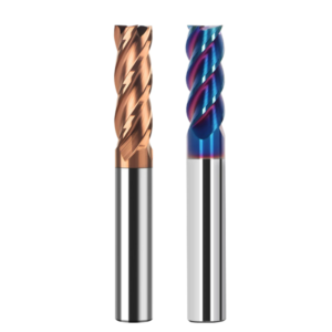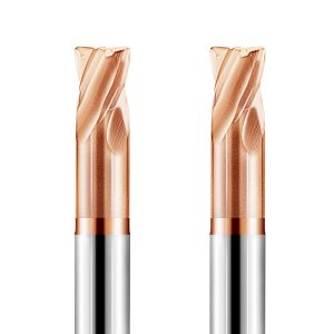
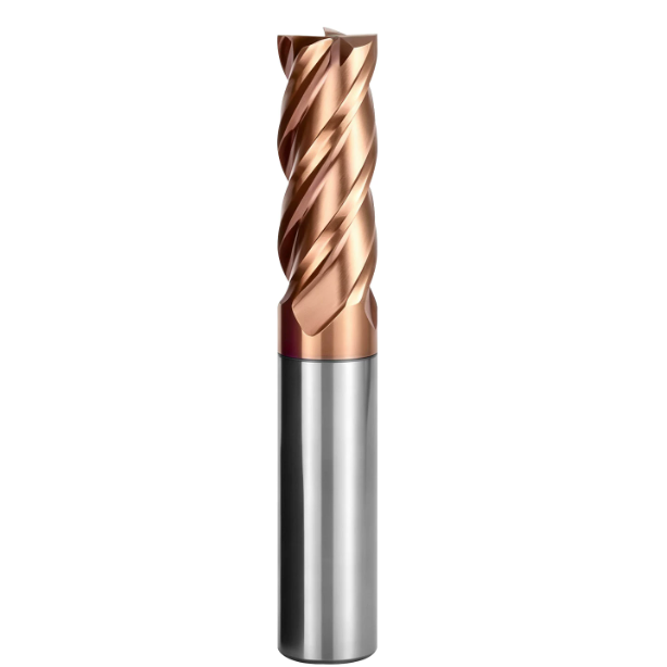
A German precision mold shop recently contacted our engineering team with an urgent problem. They were milling cold-work stamping die inserts hardened to 65 HRC, but their tools failed after cutting just two parts. They ran standard 4-flute carbide end mills rated for hardened materials at 18,000 RPM, taking speeds directly from the catalog packaging. Within three minutes of cut engagement, every cutter suffered micro-chipping or catastrophic fracture.
The customer suspected defective PVD coatings or poor transverse rupture strength in the carbide substrate. We reviewed their CAM programs, cutting parameters, and microscopic tool wear images. The root cause was immediate: the tooling was fine, but their chosen spindle speed for hardened steel violated the basic mechanics of ultra-hard milling.
We encounter this exact failure mode across machine shops throughout North America and Europe. Machinists often apply habits from pre-hardened steels (30–45 HRC) to fully quenched tool steels. Once a workpiece exceeds 60 HRC, cutting mechanics change completely. Metal removal is no longer clean plastic shear flow. It turns into brittle micro-fracture and intense dry friction under extreme mechanical load.
A 10% error in surface cutting speed (Vc) creates an immediate chain reaction. Setting your HRC65 end mill RPM too high generates intense dry friction that breaks down AlTiN/AlCrN coatings, triggering thermal fatigue in the carbide. Setting it too low overloads the cutting edge, causing brittle chipping instead of normal flank wear.
This problem multiplies on 3D finishing paths. When setting your ball nose end mill RPM, failing to account for the zero-speed center dead zone causes the tool tip to plow and crush the steel rather than shear it.
Many experienced CNC machinists and CAM programmers face this dilemma: machining handbook formulas look reliable on paper, so why do standard spindle speed calculations fail completely on actual 65 HRC hardened steel?
Determining RPM for HRC65 End Mills: Why Must Cutting Speed (Vc) Be Reduced at 65 HRC?
At 65 HRC, cutting zone mechanics change radically compared to softer, pre-hardened steels. The massive increase in shear yield strength converts mechanical energy into intense, localized friction. Standard finishing speeds cause cutting edge temperatures to quickly surpass coating limits. Slowing down your cutting speed is not a compromise; it prevents immediate thermal failure.
We advise machine shops to narrow cutting speeds to 40%–60% of standard baseline values. Excessive speeds degrade the carbide substrate behind the coating when cutting hardened martensite. Setting the right HRC65 end mill RPM requires shallow axial cuts and fine feeds. This approach evacuates chips before thermal bonding occurs, balancing process stability with tool life.
The Lower Limit of Carbide End Mill RPM and the Critical Point of “Red Hardness” in Machining Quenched Die Steels
Running spindle speeds too low causes a different set of severe problems. Below a critical speed threshold, the cutting action shifts from shearing to forced compressive plowing. Specific cutting resistance spikes, increasing tool deflection. Minor spindle torque ripple at low RPM creates alternating bending loads, causing rapid micro-chipping.
Dialing in your carbide end mill rpm depends on maintaining the substrate’s hot hardness. Silicon-rich coatings like AlTiSiN need sufficient friction heat to build a protective aluminum oxide layer. However, the core substrate must stay below its annealing threshold. We read chip color—aiming for light blue to dark grey—to verify the tool cuts within a safe thermal window.
A Common Misconception Among Western Engineers: Micro-Chipping vs. Wear Caused by Excessively High Spindle Speeds
Many programmers assume that higher spindle speeds automatically yield a better surface finish. In ultra-hard milling, this assumption frequently backfires due to dynamic impact loads. Tiny imbalances or toolholder runouts multiply at elevated speeds. These variations cause continuous, violent fluctuations in effective chip thickness.
Every radial runout deviation strikes the hardened part like a miniature hammer blow. Combined with intense cutting temperatures, this dynamic impact breaks the sharp edge before normal wear develops. In our shop audits, our primary fix is simply lowering the end mill spindle speed. Eliminating micro-vibration restores edge stability and preserves cutting geometry.
Balancing Chip Evacuation and Rigidity: Setting Spindle Speeds for 4-Flute End Mills and Principles for Speed Reduction
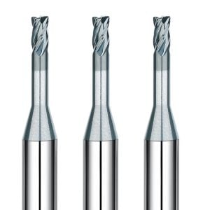
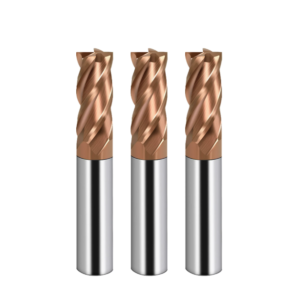
Four-flute tools offer the heavy web thickness and high bending resistance needed for hard die milling. The trade-off is much tighter flute gullet capacity. In slots or semi-enclosed pockets, hard chips pack into these narrow pockets. Re-cutting trapped chips triggers rapid edge fracture or snaps the tool shank entirely.
When setting a 4 flute end mill spindle speed, we adjust RPM based on cavity confinement. If axial depth exceeds 0.5D, we proactively reduce spindle RPM by 10%–15%. We pair this with high-pressure air blasts to blow hot chips clear of the cut. Trading away a fraction of cycle time eliminates chip packing and ensures reliable, unattended machining.
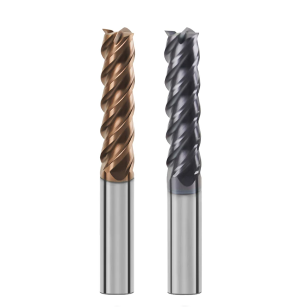
Recommended End Mill RPMs for Hardened Die Steels and Superalloys Based on Empirical Testing
We tell our tooling clients one fundamental rule: never treat all hardened materials alike. Workpieces above 60 HRC vary drastically in microstructural composition. Cold-work steels contain coarse chromium carbides, while hot-work steels demand high thermal-fatigue strength. Selecting your cutting parameters using a simple hardness number leads to premature edge fractures before completing the first pass.
Through extensive in-house cutting trials and field support across North America and Europe, we established dynamic speed baselines for quenched workpieces. Balancing chip evacuation resistance against coating thermal thresholds creates a reliable operating envelope. Use this baseline to determine a safe end mill rpm for steel without risking catastrophic tool failure on unfamiliar raw stock batches.
For Cold-Work Die Steels: Recommended End Mill Speeds for D2 Tool Steel
Machining quenched D2 presents severe abrasive challenges due to its dense chromium-carbide network. In a recent stamping die project, the inserts measured a full 65 HRC. At this level, carbides inside the steel act like grinding stones against tungsten carbide flutes. Running standard surface speeds strips the cutting edge within minutes, requiring us to restrict Vc strictly to 40–55 m/min.
When programming Ø6 mm or Ø10 mm cutters, we balance roughing and finishing shear loads differently. Pushing high rotational speeds during finishing passes generates severe localized friction, introducing tensile residual stresses and surface micro-cracks. We dial back the end mill speed for D2 tool steel by 10%, pairing it with smooth climb milling to safeguard tool life and surface integrity.
End Mill RPM Strategies for Hot-Work Die Steels and Bearing Steels: H13 (Pre-hardened/Quenched) vs. GCr15
Quenched H13 and through-hardened GCr15 (52100) respond completely differently to cutting loads. H13 heat-treated to 52–55 HRC retains toughness, but its poor thermal conductivity traps intense heat directly at the cutting edge. Fully quenched GCr15 (62–64 HRC) features a dense martensitic matrix that is hypersensitive to chatter. We design completely separate milling strategies for these alloys based on thermal dissipation and material brittleness.
With quenched H13, we safely run toward the higher end of the cutting speed window using high-lubricity coatings. For hardened bearing steel bores, we strictly throttle the end mill rpm to prevent spindle harmonics from spalling the brittle track. Check your chips: if evacuated chips stay a light straw yellow rather than dark purple or black, your spindle speed sits safely within the sweet spot.
Feed Coordination Under High-Rigidity Clamping: Linking Feed per Tooth ($f_z$) with Rotational Speed to Prevent “Rubbing-Induced Work Hardening”
A common mistake in hard milling is decoupling rotational speed from feed rate. Many CAM programmers drop feed-per-tooth drastically to protect brittle carbide flutes. When chip thickness drops below the edge-hone radius (0.005–0.015 mm), the tool cannot shear the material. It begins rubbing and burnishing against the work-hardened surface, instantly destroying flank coatings.
Spindle speed must stay synchronized with minimum effective feed per tooth. Lock the cutter in rigid shrink-fit or hydraulic holders with overhang under 3D. When adjusting your end mill spindle speed, recalculate fz so flutes penetrate cleanly beneath the prior pass’s hardened skin. A slightly lower spindle speed with a healthy chip load beats high-RPM rubbing every time.
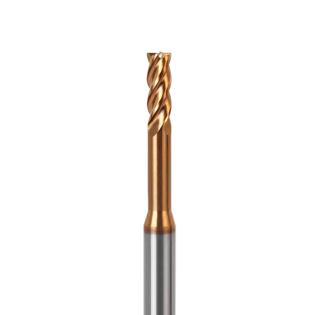
Flat End Mill vs Ball Nose End Mills: How Structural Differences Critically Affect Spindle Speed
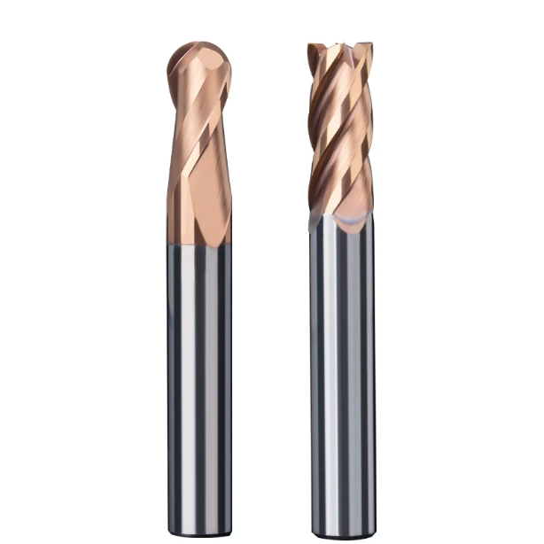
We frequently see programmers apply flat-end mill parameters directly to 3D ball-nose toolpaths. In soft alloys, this mismatch merely degrades finish, but at 65 HRC it destroys tools immediately. A flat-end mill cuts at its full outer diameter with uniform surface speed across the peripheral flutes. A ball-nose cutter’s radius drops along a sinusoidal curve down to absolute zero at the center apex.
At 65 HRC, cutting resistance spikes when surface speed drops across the ball profile. Running identical spindle values forces the ball apex to plow and crush hardened martensite. This localized compression triggers instant spalling at the tool center. Accurately calibrating end mill spindle speed requires separate cutting models based on exact tool engagement geometry.
Calculating RPM and Effective Cutting Diameter Compensation for 4-Flute Flat-End Mills in Roughing and Semi-Finishing
For 4-flute flat-end mills, roughing success depends on how radial depth (ae) dictates flute engagement. When roughing large hardened inserts, we implement dynamic trochoidal paths with radial step-overs of only 5%–10% of cutter diameter. This thin-chip approach minimizes the engagement arc, allowing the flutes to cool between rotations so operators can boost material removal rates.
However, programmers often ignore the entry impact loads that accompany low radial engagements. Thin chips reduce cutting zone heat, but the entry shock against 65 HRC steel increases significantly. When calculating carbide end mill rpm, we reduce theoretical speeds by 8% to 12%. This buffer protects sub-micron carbide grain boundaries from micro-fractures, maintaining straight, durable cutting edges.
Avoiding the “Dead Point” at the Center: Real-World Tilt Angle Correction for Ball Nose End Mills in Hardened Steel
The greatest vulnerability of a ball cutter in hardened dies is the dead center where surface speed hits zero. We often see operators plunge vertically into deep pocket corners, stripping the tip coating in seconds. Without surface speed, metal shearing stops completely; the tool tip simply extrudes hard steel via dry friction, causing thermal spikes and immediate center micro-cracks.
The cleanest fix on 4-axis and 5-axis machines is applying a 10° to 15° lead or tilt angle. Angling the tool pulls the contact zone away from the dead center onto the spinning curved edge. When determining your ball nose end mill RPM for hardened steel, calculate spindle values using this tilted contact point. This setup eliminates zero-speed plowing and clears chips smoothly away from the cut.
Calculating Effective Cutting Diameter (D_eff) and Determining Practical RPM for Ball Nose End Mills in 3D Surface Finishing
On free-form mold contours, programming spindle speeds from nominal diameter (D) starves the cutting edge of surface speed. Shallow finishing cuts only engage a fraction of the ball profile. Actual cutting speed depends entirely on the D_eff, calculated as:
Finishing at ap = 0.08 mm with a Ø6 mm cutter yields an effective diameter of just 1.38 mm, cutting surface speed by over 75%. To maintain a clean shearing action on 65 HRC surfaces, recalculate your ball nose end mill rpm using D_eff.
| Tool Spec (D) | Axiale diepte (ap) | Effective Diameter (Deff) | Base Cutting Speed (Vc) | Practical Spindle Speed (RPM) |
| R1.5 (Ø3 mm) | 0.05 mm | ~ 0.77 mm | 35–45 m/min | 14,500-18,500 |
| R3.0 (Ø6 mm) | 0.08 mm | ~ 1.38 mm | 45–55 m/min | 10,500-12,500 |
| R5.0 (Ø10 mm) | 0.12 mm | ~ 2.18 mm | 50–60 m/min | 7,300-8,800 |
| R6.0 (Ø12 mm) | 0.15 mm | ~ 2.67 mm | 55–65 m/min | 6,500-7,800 |
Fine-tune these RPM values around your machine’s dynamic sweet spot. If slight harmonic chatter appears at higher spindle speeds, drop your speed slightly; avoiding vibration is critical when finishing mirror-quality mold cavities.
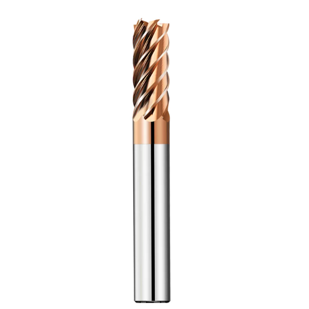
Practical Techniques for Extending End Mill Life: The Roles of Coatings, Chip Evacuation, and Tool-Holder Rigidity
In our field investigations, over half of all tool failures do not stem from incorrect cutting parameters. At 65 HRC, cutting loads concentrate along a razor-thin contact boundary. Any dynamic deflection or thermal fluctuation multiplies stress on the cutting edge. Toolholding rigidity, flute clearance, and thermal-barrier coatings define your actual tool life ceiling.
Focusing solely on raw carbide substrate grades ignores the mechanical rigidity required to support them. If toolholder runout exists or chip clearing hesitates for a split second, micro-chips re-cut instantly. We treat the freesbit, toolholder, and coolant blast as a unified, rigid system. Ignoring mechanical system rigidity makes catalog tool-life benchmarks virtually useless on the shop floor.
The Cooling Trap in High-Heat Environments: Why We Prohibit Liquid Coolants—and Recommend Cold Air or MQL—for 65HRC Machining
Applying flood coolant to 65 HRC cuts is one of the most destructive habits we see. The cutting zone rapidly hits 800°C during chip shear. As each flute exits the cut, flood coolant instantly shocks the tool tip. This violent thermal cycling triggers massive thermal gradients between the sub-micron substrate and its nano-coating.
Under magnification, wet-milled tools develop dense comb cracks running perpendicular to the cutting edge. These thermal cracks cause the cutting edge to crumble almost immediately. We prohibit liquid coolants at 65 HRC in favor of dry, high-pressure air (0.4–0.6 MPa) or MQL. High-velocity air evacuates glowing micro-chips instantly, stabilizing cutting temperatures and preventing thermal shock.
If Tool Holder Runout Exceeds 0.005 mm, Even the Most Precisely Calculated Spindle Speed for an End Mill Becomes Meaningless
Machinists often ask us why mathematically sound CAM speeds still fail on the machine. In most cases, a quick check with a 0.001 mm dial test indicator reveals the culprit. At 65 HRC, chip loads are paper-thin, often measuring just 0.015–0.03 mm per tooth. A runout of 0.006 mm overloads one flute while leaving the opposite tooth sliding and burnishing.
This uneven mechanical load causes single-tooth chipping, initiating severe harmonic chatter. Once total runout passes 0.005 mm, your theoretical end mill spindle speed calculation becomes physically invalid. We replace standard ER collet chucks with precision shrink-fit or high-rigidity hydraulic holders. Keeping cutter stick-out under 3D eliminates micro-vibration, ensuring your spindle calculations work in practice.
Fine-Tuning Spindle Speed to Optimize End Mill Durability in High-Speed Machining (HSM) with Shallow Axial Depth (ap) and Large Radial Step-over (ae)
High-speed finishing paths using shallow axial depths (ap = 0.05–0.15 mm) and wide step-overs (ae) are standard for hardened dies. Cutting forces redirect along the machine tool’s rigid horizontal plane, preventing vertical deflection. However, wide radial step-overs shorten the tool’s cooling window in open air, concentrating thermal loads right on the corner radius.
To preserve the working life of your end mill bit, avoid treating theoretical values as static limits. When taking wider step-overs, we drop spindle RPM by roughly 5% while keeping feed per tooth steady. This adjustment replaces abrasive surface rubbing with a positive micro-shear. It suppresses thermal degradation, delivering reliable, repeatable flank wear over long unattended finishing cycles.
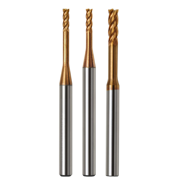
Troubleshooting 65HRC Machining: Adjusting RPM Based on Wear Patterns in Ball Nose and Flat End Mills
A worn cutting edge viewed under an optical shop microscope tells the honest truth. When a cutter fails in 65 HRC steel, blindly swapping tools without diagnosing the wear solves nothing. Tool wear reveals the balance between cutting heat, cyclic shock, and chip evacuation. Every micro-fracture or discoloration pattern points to a specific parameter mismatch.
Reading wear patterns is a fundamental troubleshooting skill for CAM programmers and shop-floor machinists. Differentiating between steady flank abrasion, thermal softening, and impact chipping lets you dial in your spindle speeds accurately. Inspecting these mechanical patterns helps you quickly stabilize a kogelkopfrees or square cutter before tool damage scraps the part.
Blue Discoloration at the Tool Tip and Premature Crater Wear: A Step-Down Strategy for Excessive RPM with Carbide End Mills
Noticing dark blue burnishing on the tool margin or rapid crater wear on the rake face indicates excessive friction. At 65 HRC, cutting temperatures exceed the oxidation threshold of the coating. This excessive heat leaches the cobalt binder phase from the carbide substrate. Stripped of its structural support, the softened cutting edge rubs away rapidly.
If your tool shows heat discoloration or thermal craters, apply a stepped speed reduction immediately. Keep your chip load and axial cut depth constant, but drop your carbide end mill rpm by 12% to 15%. Direct high-pressure air nozzles straight at the tool-workpiece interface. Once chips turn from dark blue to uniform light grey, you are back in a safe thermal zone.
Chipping at the Center or Severe Chatter: Diagnosing Whether the Issue is Insufficient RPM or Excessive Feed for Ball Nose End Mills
Distinguishing between speed starvation and feed overload on a chipped ball cutter comes down to fracture location. If fractures cluster right at the spherical apex, feed overload is rarely the cause. It indicates zero surface speed at the center dead point, where the tool tip crushes hardened steel rather than shearing it. If the entire peripheral flute shows chipping with audible screeching, excessive feed load is driving harmonic chatter.
When deep 3D cavities trigger center chipping on a ball nose end mill, tilt the tool axis 10° to 15° to shift the cut away from the dead zone. On 3-axis mills where vertical engagement is fixed, increase spindle RPM by 10% while stepping down feed per tooth by 0.005 mm. This reduces entry impact forces and prevents center-point fracturing.
Balancing Surface Finish (Ra < 0.4 μm) and Tool Life: Optimizing Spindle Speed and Feed Rate for Final Finish-Milling of Hardened Molds
Achieving mirror finishes (Ra < 0.4 μm) while preventing dimensional drift across long passes is a delicate balance. Running the spindle at maximum speed to minimize cusp heights often backfires. Tiny dynamic imbalances at extreme RPM induce high-frequency harmonics, leaving visible micro-chatter bands across hardened die cavities.
Focus on D_eff compensation and rigid runout control instead of pushing raw spindle limits. Calculate your target HRC65 end mill RPM using the actual contact diameter at your finishing depth, maintaining climb milling throughout. If you are dealing with challenging mold geometries, tight-radius ribs, or inconsistent heat-treat batches, reach out to review your setup. Sharing machine parameters, spindle limits, and alloy specs helps us fine-tune a dependable, production-ready solution.