
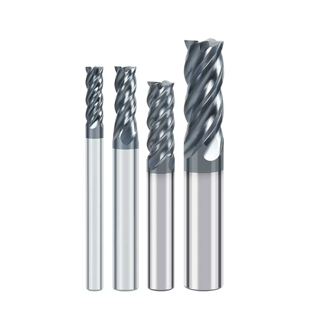
Last month, we helped an Ohio mold shop troubleshoot an urgent issue. Their 5-axis machining center was struggling with severe tool life inconsistency while milling D2 heat-treated mold inserts at 56 HRC. The machinist had tried several standard catalog cutters, yet micro-chipping appeared along the outer corner in under fifteen minutes. This caused sidewall deflection, out-of-tolerance parts, and expensive spindle downtime.
We have seen this exact scenario for over fifteen years while supporting die and mold facilities across North America and Europe.
When cutting materials past 50 HRC—like 1.2379, H13, or S7—many shops instinctively reduce cutting speeds or swap brands. However, our cutting trials show the brand is rarely the root issue. Hardened steel fundamentally changes cutting zone physics and stress distribution. Once hardness exceeds 50 HRC, standard end mill bits for steel cannot survive without dedicated geometries designed for severe compressive loads.
If the carbide substrate lacks transverse rupture strength, or if the edge honing cannot dissipate high shear stress on entry, the corner chips immediately. Machining hardened cavities requires sub-micron grain structures, high-temperature PVD coatings, and unequal helix angles to suppress harmonic chatter. Every single micron matters when dialing in tool life and surface finish.
For high-value mold components taking dozens of machine hours, are your toolpaths fighting the steel’s hardness, or did your chosen carbide end mill cutter lack the edge strength to survive the cut from the start?

Why Standard Tooling Fails on 50+ HRC Materials: Field Observations on End Mill Bits for Steel
In our tool manufacturing facility and customer trial runs, we examine countless failed cutters. Machinists often run standard tooling meant for pre-hardened alloys on 50+ HRC steel. The cut usually begins with a high-pitched screech. Standard cutters use positive rake angles and deep flutes for chip clearance. On hardened die steel, this thin edge profile collapses instantly under extreme cutting resistance.
Our shop data shows that cutting 50+ HRC steel demands a balance between core stiffness and chip space. General-purpose end mill bits for steel simply lack the web thickness needed to absorb instantaneous radial loads. When an edge profile is too sharp, micro-chipping develops within seconds. This leads to heavy burrs, poor part finishes, and dangerous spindle load spikes.
Thermal Cracking vs Mechanical Chipping on Steel End Mills
Under a 500x microscope, we first inspect crack orientation to diagnose tool failure. Micro-cracks running perpendicular to the cutting edge indicate thermal fatigue. As the tool enters and exits the cut, edge temperatures spike past 800°C and plunge instantly. This severe thermal shock fractures the coating bond. For this reason, we recommend high-pressure dry air blasts instead of flood coolant to protect steel end mills from rapid thermal cracking.
Mechanical chipping, on the other hand, leaves rough, uneven fractures along the corner radius. We often see this when an operator skips corner deceleration or hits uneven stock allowance. The resulting shock load shears the brittle carbide tip. Checking spindle taper contact, balancing toolholders, and applying a proper edge hone (10–15 μm) will stop chipping far more effectively than merely dropping your RPM.
The Cost of Tool Deflection When Using Long-Reach End Mill Bits for Steel Cavities
During rest-milling and corner pick-up in deep mold cavities, excessive tool overhang quickly ruins dimensional accuracy. You have likely seen this on the floor: the top of the pocket measures perfectly, but the bottom retains unwanted taper from tool push-off. Machinists often add spring passes to clean the wall. However, this causes severe rubbing, accelerates flank wear, and work-hardens the surface for bench polishing.
Tool deflection increases with the cube of the overhang length. Every extra 10 mm of reach drastically reduces bending rigidity. When clearing deep pockets in hardened steel, avoid standard straight-shank extended tools. We recommend engineered long reach end mill bits for steel cavities with tapered necks and reinforced cores. Keeping the radial stepover under 5% Dc ensures straight sidewalls and prevents catastrophic tool snap.
Matching the Right End Mill Types to Hardened Die & Mold Features
Cavity geometry directly dictates the mechanical loads and thermal spikes a cutter experiences. In many shops, machinists habitually run a single tool for both roughing and finishing hardened inserts above 50 HRC. However, this shortcut causes extreme cutting force spikes in hardened steels. High-hardness mold blocks are unforgiving of localized stress concentrations during heavy pocketing or wall finishing.
Data from our partner mold shops across North America shows that premature scrap often stems from mismatched tool geometries. Selecting the right end mill types does more than just extend tool life; it establishes predictable cycle times and holds tight tolerances. Proper tool staging also prevents catastrophic tool breakage during semi-finishing caused by uneven stock left by preceding operations.
Carbide Corner Radius End Mills: The Real Workhorse for Pocketing and Contouring
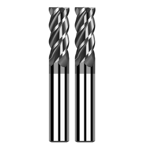
For roughing and semi-finishing hardened cavities, bull-nose cutters are our primary workhorses. Standard square cutters have fragile 90-degree corners that concentrate stress and trigger micro-chipping under high radial loads. Adding a corner radius (such as R0.5 or R1.0) distributes the resultant cutting forces across the arc. This reinforced cross-section provides the impact toughness needed for heavy interrupted cuts.
When running carbide corner radius end mills in large pockets, chips transition smoothly from thick to thin. This chip formation delays crater wear and keeps heat away from the primary cutting zone. While the corner radius leaves slight rest-material for subsequent cleanout steps, it drastically reduces the risk of floor gouging and catastrophic edge failure in hardened die steel.
Carbide Flat End Mills: Precise Wall Finishing and Flat-Bottom Cleanout
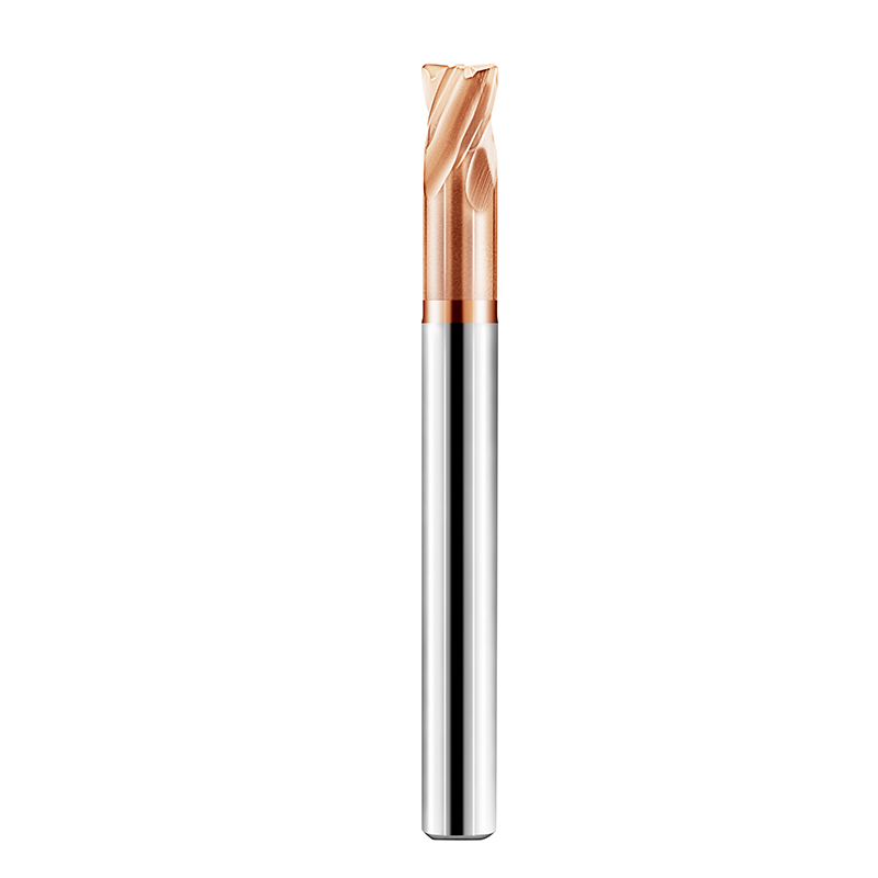
When squaring parting lines, vertical insert walls, or flat floors, square end mills remain irreplaceable. However, engaging a sharp, unreinforced corner in 50+ HRC steel will quickly destroy the cutter. To protect the junction between the peripheral and end teeth, we apply a microscopic negative land (a 0.03–0.05 mm protective micro-chamfer) to reinforce the edge against high-frequency cutting impacts.
For finishing sidewall verticality and surface finish, we recommend high-rigidity, stub-length carbide flat end mills. Machinists should pair a small radial stepover (ae) with full axial flute engagement (ap). This light-load strategy eliminates multi-pass step marks, minimizes tool deflection, and holds verticality tolerances within tight micron limits.
Selecting Other End Mill Types for 3D Mold Profiling: Ball Nose vs. High-Feed Cutters
Balancing metal removal rates against scallop height is a constant challenge on complex 3D mold contours. During high-volume roughing of deep, curved cavities, we prefer high-feed cutters featuring small lead angles. These tools leverage chip thinning to direct cutting forces axially up the spindle. This allows aggressive table feeds at shallow depths of cut without overloading the tool.
For final surfacing, ball-nose cutters deliver smooth, continuous toolpaths. However, operators must account for the zero-surface-speed dead zone at the exact tool tip. Running a ball nose perpendicular to the workpiece causes rubbing and rapid center wear. Evaluating end mill types for 3D mold profiling requires combining 5-axis tilt angles with stable side-cutting to achieve mirror-like finishes.
Engineering Behind the Best Carbide End Mill Cutter for Hardened Steel
When grinding cutters for 50+ HRC steel on our 5-axis CNC tool grinders, our focus centers on cutting-zone thermodynamics. Machinists often ask why two identical-looking tools yield wildly different tool lives in hardened D2 or H13. The difference lies in invisible micro-engineering details: sub-micron grain sizing, precise edge honing, and plasma coating adhesion.
Machining hardened tool steels requires a delicate balance of thermal and mechanical properties. A high-performance carbide end mill cutter must withstand severe frictional heat, interrupted mechanical shocks, and harmonic chatter. Achieving high metal removal rates demands balancing core web rigidity against chip pocket volume, while pairing substrate toughness with extreme hot hardness.
Sub-Micron Carbide Substrates and High-Heat PVD Coatings for Steel End Mills
Machining hardened tool steel requires abandoning medium-to-coarse carbide grades. We formulate our substrates using 0.2 to 0.5-micron tungsten carbide powder with an 8% to 10% cobalt binder. Excessive cobalt lowers hot hardness and causes edge softening at high temperatures. Conversely, insufficient cobalt makes the tool brittle. A uniform nano-grain structure provides maximum wear resistance and edge stability.
Because cutting temperatures can reach 1,000°C, high-heat PVD coatings are essential thermal barriers. In dry machining setups, we utilize high-aluminum AlCrN or AlTiN coatings that form a dense aluminum oxide layer under heat, resisting oxidation past 1,100°C. Equipping your shop with properly coated steel end mills creates an impenetrable thermal and abrasive shield against tough workpiece alloys.
Unequal Pitch & Variable Helix in Our Carbide End Mill Designs
High-frequency chatter is a primary cause of chipped cutting edges and poor surface finishes in hardened steel cavities. With traditional symmetrical flutes, each tooth engages the workpiece at identical intervals. This rhythmic impact quickly matches the natural harmonic frequency of the spindle setup, causing self-excited chatter that can shatter carbide cutting edges.
To break this resonance cycle, our modern carbide end mill designs incorporate unequal flute indexing and variable helix angles (like 35°/38°). This asymmetrical geometry disrupts cutting force frequency pulses and dampens vibrations right at the cut. As a result, machinists gain a broader, stable machining window at higher speeds without sacrificing surface finish quality.
Negative Rake Angle & Micro-Honed Edges on End Mills for Steel
While positive rake angles work well for shearing soft carbon steel or aluminum, they are too weak for 50+ HRC steels. The heavy cutting resistance of hardened alloys easily breaks delicate, razor-sharp edges. We engineer a micro-negative radial rake angle to direct cutting forces into the reinforced center of the cutter, utilizing the carbide’s high compressive strength.
In addition to negative rakes, controlled edge honing is vital. Under magnification, raw ground edges reveal microscopic grinding serrations that quickly form fracture points. We utilize micro-blasting to apply a consistent 10–18 μm radius hone. This protective edge prep ensures that our end mill bits for steel enter the cut smoothly without chipping on initial impact.
Cutting Strategies: Running Carbide Flat End Mills and Radius Cutters in 50+ HRC Molds
Even with top-tier carbide grades and PVD coatings, using traditional cutting strategies on 50+ HRC steel will destroy your tool in half a shift. Hardened machining links three critical variables: thermal load, chip evacuation speed, and instantaneous contact arc. Flat and radius cutters distribute cutting forces differently, determining whether heat escapes with the chip or cooks the tool edge.
Our shop-floor data across North America shows that premature tool failure usually stems from mismatched toolpaths rather than weak carbide. Managing the motion dynamics of carbide flat end mills and bull-nose cutters during cavity roughing is essential. Modern CAM path optimization prevents sudden load spikes, ensuring tight tolerances and predictable tool life in hard steel.
Air Blast vs. Mist: Thermal Shock Control for Carbide Corner Radius End Mills
When troubleshooting 50+ HRC setups, the first thing we do is turn off the flood coolant. Water-based coolant creates severe thermal shock during interrupted milling. The cutting edge spikes to 800°C in the cut and rapidly chills upon exit, causing microscopic comb cracks that trigger edge flaking. Dry machining eliminates this destructive thermal cycling.
We strongly advocate using high-pressure dry air blasts or MQL systems. The high-velocity air blast clears chips instantly to prevent recutting and abrasive flank wear. When roughing deep mold cavities with carbide corner radius end mills, maintaining a dry cutting zone significantly slows down crater wear and stabilizes your cycle.
High-Efficiency Milling (HEM) Parameters for End Mill Bits for Steel
Traditional deep radial cuts concentrate mechanical load and heat directly onto the fragile tool corner. Instead, we implement High-Efficiency Milling (HEM) strategies featuring a large axial depth (1.0–2.0x $D_c$) and a light radial width of cut (5–10% Dc). This spreads cutting friction evenly across the entire peripheral flute length.
Taking advantage of the chip thinning effect allows you to run aggressive table feeds and higher surface footage safely. When milling 55 HRC D2 or H13 steel, this light radial engagement carries heat away in the chips before it penetrates the core. Properly applied, modern end mill bits for steel achieve massive metal removal rates with minimal cutting resistance.
Ramp-In and Trochoidal Entry to Protect Your Carbide End Mill Cutter
Direct Z-axis plunging into hardened steel is a recipe for instant tool breakage. The center cutting speed of a flat cutter drops to zero, generating massive axial thrust that shatters the center web and corner radius. We mandate continuous helical interpolation or low-angle linear ramping (1° to 2° max) to keep the bottom teeth slicing smoothly.
When opening narrow, deep slots, linear plunging packs chips and binds the tool. Trochoidal entry paths protect the cutter by cutting circular arcs that provide built-in relief for chip clearance and cooling. This smooth entry eliminates shock load spikes, providing the best mechanical protection for your carbide end mill cutter.
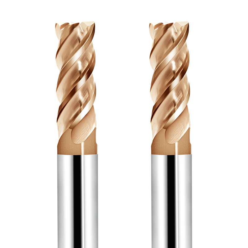
When Off-the-Shelf Tools Fall Short: Engineering Custom Carbide End Mills for Specialized Steel Molds
Standard catalog tools are built around general-purpose compromises that struggle in narrow ribs, deep pockets, or specialized chamfers. Forcing standard tools into 50+ HRC cavities often leads to excessive spring passes, chatter, and compromised surface finishes. These workarounds increase machine-hour costs and introduce dimensional blending errors between setups.
When standard tooling hits a wall, our engineering approach focuses on reallocating tool core mass to match specific pocket geometry. By optimizing neck reliefs, flute lengths, and edge hones, engineered custom carbide end mills eliminate non-cutting cycle time. They deliver maximum rigidity and process reliability at the absolute limit of your machine’s capability.
Designing Necked and Extended-Reach Custom Carbide End Mills for Deep Pockets
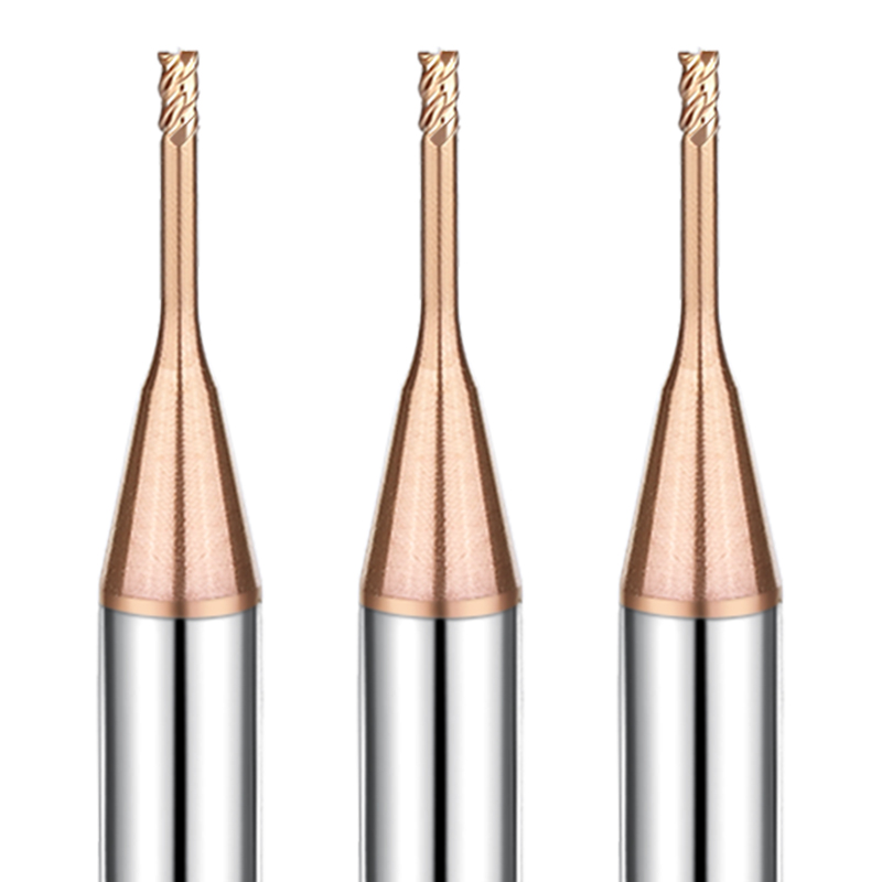
In deep injection molds, tool reach and vibration resistance constantly fight each other. Machinists often run long-flute tools to clear high walls, but excess flute length severely degrades torsional rigidity, causing taper errors. We solve this by grinding short, high-rigidity flutes paired with a tapered, relieved neck.
Relieving the non-cutting neck diameter by 0.2–0.5 mm eliminates wall rubbing while preserving shank stiffness. When designing extended-reach custom carbide end mills, we keep the cutting flutes as short as the stepdown requires. This design stops tool push-off and prevents chatter-induced breakage in deep-cavity work.
Custom Step and Corner Chamfer Configurations in Custom Carbide End Mills
Mold inserts often feature complex stepped counterbores, alignment flats, and edge chamfers that typically require three separate tools. Each tool change accumulates micron-level positioning errors in hardened steel while eating up cycle time. Consolidating these features into a single engineered tool delivers immediate shop-floor savings.
Grinding multiple step diameters, blended radii, and chamfers onto a single blank allows complete feature finishing in a single pass. When manufacturing multi-step custom carbide end mills, we adjust helix angles across each step to balance cutting forces. This cuts cycle times by over 30% while holding strict true-position tolerances.
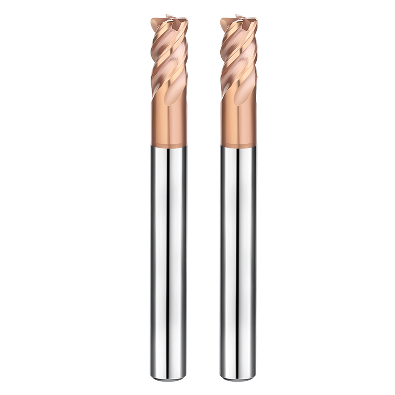
Case Study & Troubleshooting: Maximizing Tool Life of Steel End Mills in D2 and H13 Molds
Theoretical cutting parameters provide a baseline, but workholding rigidity, machine kinematics, and heat-treat stress dictate real-world outcomes. Extending tool life in 50+ HRC steel rarely requires rewriting your entire CAM program. It usually comes down to catching subtle process errors right at the spindle nose.
In our field experience, D2 and H13 mold steels exhibit distinct, predictable failure modes. Troubleshooting your steel end mills requires evaluating tool wear alongside toolholder runout and machine dynamics. Below are two real-world cases where small geometry tweaks and clamping fixes stabilized tool performance.
Solving Corner Chipping on Carbide Corner Radius End Mills in D2 Tool Steel (58 HRC)
A North American stamping die shop was experiencing corner chipping while milling 58 HRC D2 cavities with standard R0.5 four-flute cutters. D2 contains hard eutectic carbides that quickly abrade sharp edges. Under our microscope, the worn tools showed only a 6 μm factory hone, which fractured immediately upon hitting hard carbide clusters.
We upgraded the tool to an R1.0 radius, increased the edge hone to 15 μm, and switched from coolant to a dry air blast. This expanded the load-bearing cross-section and cushioned edge impact. If you face frequent corner chipping on high-carbon steels, try stepping up your corner radius and verifying edge preparation on your carbide corner radius end mills.
Eliminating Chatter and Step Marks When Running Carbide Flat End Mills on H13 Inserts
A German mold facility struggled with chatter marks and blend steps while finish-milling vertical sidewalls on 52 HRC H13 inserts. The shop lowered speeds, but the chatter worsened. Our on-site dial indicator revealed 8 μm of radial runout (TIR) at the tool tip, causing one flute to take the entire cutting load.
We moved the cutters into high-rigidity shrink-fit holders, reducing total runout below 3 μm, and tuned the spindle speed away from the resonance frequency. All four flutes engaged evenly, producing a flawless sidewall finish. If you battle chatter steps, inspect your holder runout before altering feed rates with carbide flat end mills.






