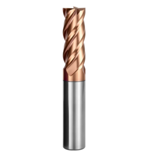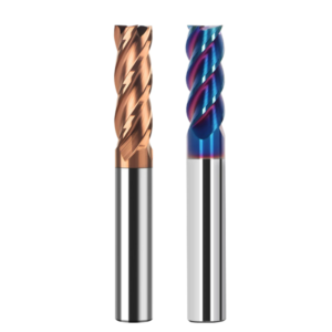
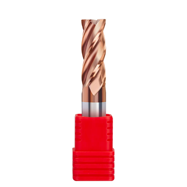
Last month, a Texas mold maker reached out to us with a severe line-down crisis. They were hard-milling cold-work tool steels (DC53 and vacuum-treated D2) at HRC64–66 for Tier 1 automotive injection molds. To reduce cutting forces and chase a high surface finish, the shop supervisor insisted on using an untreated, razor-sharp tool.
The result surprised the client, but not us. Less than four minutes in, the cutting edges developed severe carbide end mill edge chipping before normal flank wear could even form. Cutting forces spiked instantly, high-frequency chatter screamed across the machine, and the tool tip fractured. This catastrophic failure left deep gouges on a high-value cavity.
Over the past sixteen years of solving milling problems across Europe and North America, we have seen this scenario play out hundreds of times. When a tool breaks in hardened steel, machinists instinctively blame machine rigidity, holder balance, or coating adhesion. However, inspection under a 3D white-light interferometer reveals the true culprit: neglected HRC65 end mill edge preparation.
Above HRC60, metal cutting shifts from shear-slip chip formation to intense compressive extrusion and plastic deformation. A naturally sharp, fragile wedge lacks the mechanical strength to survive shock loads exceeding hundreds of megapascals. Without proper end mill edge honing, microscopic carbide grains undergo brittle fracture almost immediately.
Have you ever watched an expensive, ultra-hard milling tool fail within minutes—without ever checking that 15-micron edge radius?
The Reality of Machining Hardened Die Steel: Tool Life and Chipping Resistance—Honed Edges vs. Sharp Edges
Many machinists still believe that sharper edges always yield lower cutting resistance and better finishes. That rule works for aluminum or pre-hardened steels below HRC45. However, on HRC65 tool steel, an untreated edge is a liability. Under extreme workpiece yield strength, chips are extruded rather than sheared off, throwing massive shear reaction forces back onto the tool tip.
Through years of field troubleshooting, we see a dramatic contrast when comparing a honed edge vs sharp edge end mill. A sharp edge cuts with low initial drag, but fractures instantly against hard carbide inclusions. A controlled micro-radius adds slight radial force early on, but provides critical bulk support. Understanding this micro-mechanical interface is essential before selecting any hardened steel milling tools.
Early-Stage Failure Mechanisms of Sharp-Edged End Mills on HRC65 Mold Steel: How Micro-Chipping Occurs
In its as-ground state, a standard cutting edge carries an edge radius below 3–5 µm. Under high magnification, this wedge is as thin and fragile as glass. When the tool hits quenched martensite and undissolved carbides at 10,000+ RPM, these hard particles hammer the edge like dense abrasive grit. Because carbide has low tensile strength, this unsupported geometry quickly suffers microscopic fracture.
This initial damage sparks an irreversible chain reaction. Once micro-chipping begins, the effective rake angle shifts into an erratic, heavy negative angle. Local friction spikes, driving cutting-zone temperatures past 800°C. Mechanical cracking rapidly turns into thermal fatigue, and the entire HRC65 end mill cutting edge crumbles under cyclic shock loads.
Reshaping Cutting Force Distribution via Edge Honing: Shifting Stress from the Rake Face to the Elastic Deformation Layer
Applying a micro-honing pass after tool grinding does not mean “dulling” the tool. Instead, it re-engineers the local stress field. By placing a controlled 15–20 µm radius between the rake and flank faces, contact shifts away from the fragile tip. This relocates primary stress deeper into the solid carbide core, converting dangerous tensile stresses into favorable compressive loads.
This engineered radius also exploits localized thermal softening in the workpiece. The micro-extrusion zone ahead of the rounded edge creates a narrow plastic shear layer. Chips slide cleanly up the rake face without causing destructive force spikes. For any high-hardness application, proper edge preparation provides a structural shield that fundamentally stabilizes overall HRC65 end mill performance.
Field Test Comparison for European and American Clients: The Real Difference in Carbide End Mill Tool Life Between Sharp and Honed Edges
To resolve chronic corner-clearing breakage for a German mold manufacturer, we ran an identical head-to-head cutting trial. The test piece was cold-work die steel vacuum-quenched to HRC64.5. We used identical 6mm coated ball-nose end mills from the exact same batch. The only variable was the cutting edge: one group remained razor-sharp (rn ≤ 4 μm), while the other received a symmetrical micro-honed edge (rn = 18 ± 2 μm).
The field data settled the debate. The sharp cutters chattered within 8 minutes and suffered severe flank flaking by minute 12, ruining the cavity finish. In contrast, the micro-honed cutters ran smoothly for 52 minutes with uniform flank wear. When cutting hardened steel, controlled edge prep is what unlocks true carbide end mill tool life.
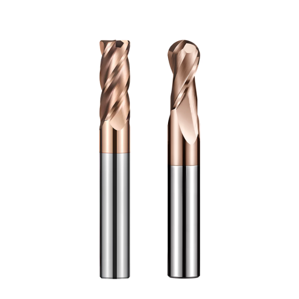
Matching HRC65 Carbide End Mill Edge Honing Profiles to Machining Scenarios and Practical Selection
When consulting us on hard milling solutions, many machinists ask for a single “magic number”—like a standard 15 µm or 20 µm hone across all setups. However, real-world stress profiles for roughing, deep-pocket wall milling, and high-speed finishing differ completely. At HRC65, hardened alloy tool steel offers massive resistance to plastic deformation; a deviation of just two microns along the cutting boundary can trigger violent tool chatter or premature micro-fractures.
Through years of tool R&D and shop-floor troubleshooting, we know edge preparation is a calculated trade-off between cutting forces and edge stability. Your choice of micro-geometry must match whether the cut is continuous or interrupted, and whether you need metal removal rates or pristine surface geometry. Dialing in the correct micro-profile for your HRC65 carbide end mill is the foundation for balancing impact resistance with precision tool life.
Radius Honing (Round Edge): The Impact-Resistance Balance Point for Roughing and Interrupted Cutting (15–25 µm)
When milling hardened cavities with cross-holes, heavy step-overs, or vertical walls, every tooth faces severe cyclical impact loads. For these interrupted roughing passes, a symmetrical round edge remains our trusted baseline geometry. By blending the rake and flank faces into a uniform arc, this profile removes microscopic grind ridges left by diamond wheels and provides solid bulk support against shock.
Frontline production data shows this radius must stay between 15 and 25 µm. Drop below 15 µm, and hard carbide inclusions will quickly chip the edge; push past 25 µm, and radial extrusion forces surge, causing severe chatter and work-hardening. For heavy-load cavity roughing, precision-controlled radius honing provides the essential safety margin that prevents catastrophic fracture.
Waterfall/Trumpet Honing: Reducing Cutting Resistance and Ensuring Smooth Chip Evacuation During Finishing
During high-speed finishing passes with shallow depths of cut, the main challenge shifts from absorbing impact to minimizing rubbing and friction. If you run a large symmetrical radius at light chip loads (fz of 0.015–0.03 mm), the tool cannot cleanly shear metal. Instead, it burnishes the workpiece, causing rapid heat buildup and surface discoloration. Here, an asymmetrical profile delivers a decisive mechanical advantage.
This geometry shifts the apex of the hone toward the rake face, typically yielding a K-factor between 1.3 and 1.6. It creates an extended lead-in ramp for smooth chip curling while keeping the flank side steep to prevent rubbing. On 5-axis 3D contours, applying an 8–12 µm waterfall honing profile drops axial thrust, suppresses chatter marks, and protects tight profile tolerances.
Chamfer + Hone: The Ultimate Solution to Chipping in Extreme Interrupted Cutting and Deep-Cavity Hard Milling
In severe setups—such as milling HRC65 powder-metallurgy tool steels or clearing corners with overhangs past 4 * D—a standard radius hone often cannot prevent deflection-induced fractures. While troubleshooting chronic tool failure on deep automotive dies, we introduced a reinforced hybrid edge: a narrow negative T-land (0.03–0.05 mm wide at -15° to -20°) ground onto the rake face, blended with a 10–15 µm protective hone.
This hybrid profile sacrifices some free-cutting action, but it creates a heavy-duty physical barrier at the point of maximum mechanical stress. The negative land redirects severe shear loads into internal compressive stresses, while the micro-hone eliminates notch stresses at the chamfer transition. In severe interrupted cuts, choosing a chamfer and hone geometry stops unpredictable fractures and stabilizes tool life.
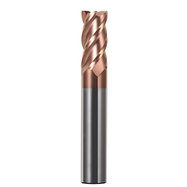
The Boundary Effects of Edge Honing Parameters on HRC65 End Mill Performance: Troubleshooting Over-Honing and Under-Honing
When auditing mold-making facilities across North America and Europe, we see shops fall into two extremes: either operators treat heavy honing as a universal cure, or they demand razor-sharp cutters out of fear of spindle load. Both extremes ruin tool predictability and waste machine capacity. At the micron scale, tool performance operates within a very narrow physical window.
Evaluating edge quality comes down to managing the boundary between edge strength and penetration resistance. Step outside this window, and your setup will protest through high-frequency screams, bad surface finishes, or fractured inserts. Learning to diagnose these mechanical boundary effects is critical to unlocking maximum HRC65 end mill performance.
The Chain Reaction of Over-Honing: Compressive Friction, Work Hardening, and Premature Chipping
If your machine emits a dull, low-frequency drone while milling cold-work die steel—and throws powdery, heat-discolored blue chips—you are likely dealing with an over-honed cutter. When the hone radius exceeds 30 µm and outstrips the feed per tooth, the tool loses its shear plane. It begins plowing and compressing the steel rather than cutting it, generating extreme friction and driving the surface past its phase-transformation temperature.
This destructive cycle is the direct consequence of over-honing. Plowing creates a brittle, work-hardened crust on the workpiece, which then violently abrades the flank face on every subsequent tooth pass. Trapped frictional heat softens the cobalt binder within the substrate, causing coating spallation, thermal fatigue craters, and rapid dimensional loss across the cavity walls.
Under-Honing and Micro-Defects: How Grinding-Induced Micro-Cracks Compromise Cutting Edge Strength
At the opposite end of the spectrum lies premature mechanical breakage caused by insufficient edge preparation. Machinists chasing free-shearing cuts often assume sharper is always better, ignoring the microscopic micro-notches left by 5-axis tool grinders. Under a white-light interferometer, an untreated edge reveals jagged serrations and grinding micro-cracks up to 3–6 µm deep that serve as prime failure points.
During initial cuts, an under-honing condition may sound smooth, but that clean hum quickly degrades into erratic clicking. Microscopic hard phases within the quenched steel strike these notch roots, rapidly propagating cracks across the wedge. This is not normal abrasive wear; it is sudden grain-boundary pullout and micro-chipping that ruins sidewall perpendicularity and sprays abrasive debris across finished surfaces.
Edge Roughness and Micro-Symmetry (K-Factor): Preventing Uneven Wear Across the Cutting Edge
Beyond specifying absolute radius values, maintaining consistent micro-geometry along the entire fluted length is frequently overlooked. In production audits, we often see cutters where only one or two flutes show heavy flank gouges while the rest look untouched. Assuming toolholder runout is verified under 3 µm, the root cause is almost always an erratic rake-to-flank ratio, widely recognized as the K-factor.
For repeatable machining in HRC65 steels, we aim for a controlled waterfall profile with a K-factor between 1.2 and 1.4, alongside an edge-zone roughness (Ra) below 0.1 µm. This micro-form guides chips away smoothly without dragging the flank face against spring-back steel behind the cut. Controlling this geometric ratio across every millimeter of the flute prevents single-tooth overload and ensures balanced, predictable wear.
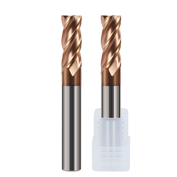
Synergy Between Coating Adhesion and the Cutting Edge: The Complete Preparation Process for HRC65 End Mill Cutting Edges
Many mold shops assume an AlTiN or nano-composite layer guarantees high wear resistance. However, our metallurgical root-cause cross-sections show that early failures rarely stem from low coating hardness. Instead, the film completely delaminates from the carbide substrate under load. The cutting edge is not just a contact zone; it is the physical foundation that anchors the coating against massive shear forces.
Without micro-geometric reconstruction, an edge cannot survive the thermal stresses of PVD. Honing and coating are interdependent links in a continuous manufacturing chain. Integrating micro-edge profiling, interface cleaning, and surface polishing is essential to build a reliable HRC65 end mill cutting edge. This synergy allows both the substrate and the coating to survive extreme milling pressures.
Pre-Coating Passivation: Eliminating Substrate Burrs to Provide a Stable Foundation for Ultra-Hard AlTiN/AlCrN Coatings
Fresh off a 5-axis tool grinder, an untreated edge looks sharp to the naked eye. Under a confocal microscope, however, that same edge reveals micro-burrs, grinding slivers, and fractured carbide grains. Placing this raw edge into a PVD chamber causes electrical charge concentration at sharp peaks. This defect sparks localized over-coating, droplet nodules, and severe internal tensile stress right at the blade line.
To eliminate this vulnerability, we apply a strict pre-coating edge preparation protocol using micro-slurry blasting or precision brushing. This process removes brittle grinding slivers and blends the cutting boundary into a uniform micro-radius. It provides an ideal surface for the epitaxial growth of AlTiN or AlCrN columnar crystals. Most importantly, it removes interfacial stress spikes, boosting coating-to-substrate adhesion.
Post-Coating Polishing: Empirical Results on Reducing Friction and Preventing Built-Up Edge (BUE)
Many tooling vendors consider the tool finished once it leaves the PVD chamber. In reality, the surface carries microscopic droplets caused by target material spitting during deposition. In hardened steel, these hard asperities act as abrasive contact points, driving up the friction coefficient and generating intense friction heat. They also serve as anchor sites for metal welding, creating built-up edges (BUE).
We confirmed the value of surface refinement through controlled shop trials on hardened tool steel. Using drag finishing, we polish the flutes and rake faces down to a mirror finish. Our field data proves that post-coating polishing dramatically reduces chip friction and clears chip flow. By minimizing interfacial heat, this secondary step delays flank-wear thermal degradation by several production cycles.
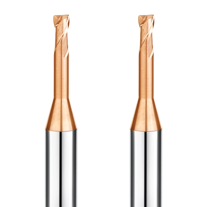
Matching Tool Rigidity with Edge Preparation: Why Long-Reach, Long-Neck End Mills Require a Differentiated Honing Strategy
Machinists often ask us if a stable 18 µm hone on a stub-length tool works equally well on an extended-reach cutter. Our direct answer is: never copy parameters blindly. Dynamic tool stiffness decreases with the cube of the overhang length (L^3). At overhang ratios beyond 4 * D, microscopic shank deflection magnifies rapidly under normal cutting resistance.
For deep-cavity dies, heavy edge preps push flexible tools past their elastic limit, causing high-frequency chatter. We engineer a tailored long reach end mill edge preparation by tightening the radius down to 8–12 µm with an asymmetrical rake bias. This geometry lowers radial push forces while protecting the carbide boundary. Suppressing harmonic vibrations preserves overall tool life far better than relying on edge mass alone.
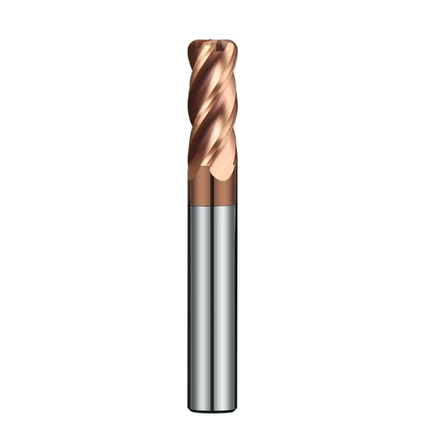
A Shop-Floor Guide to Machining Hardened Molds: Operational Recommendations for Optimizing End Mill Performance
Designing an optimized micro-geometry is only half the battle; real-world success depends on CNC programming and machine setup. Tool chipping and rough surface finishes often trace back to a mismatch between cutting parameters and micro-edge dynamics. Even the best substrate and coating combination will crumble in HRC65 steel if the toolpath strategy ignores the physical geometry of the hone.
We treat edge preparation, toolpaths, and thermal loads as an interconnected closed loop. A honed radius redefines minimum chip thickness thresholds and localized heat dissipation. If you want consistent results from an end mill for hardened mold steel, follow three shop-tested rules. These practices balance cutting forces, maintain thermal stability, and deliver clean, predictable surface finishes.
The Critical Ratio of Feed per Tooth (fz) to Honing Radius (rn): Preventing Pure Rubbing Against the Workpiece Surface
In 5-axis finish milling, operators often drop the feed per tooth (fz) down to two or three microns chasing mirror finishes. However, if your cutter carries a 15 µm edge hone, an ultra-low feed rate creates destructive rubbing. When the uncut chip thickness drops below the material’s minimum shear threshold, the tool stops cutting. It merely burnishes and work-hardens the die steel surface.
If you are milling tight 3D contours, calculate the ratio between your tooth feed and the honing radius (rn). We recommend maintaining an fz between 0.8 and 1.5 times the hone radius (rn) during finishing passes; never let it dip below 0.5 times. Proper penetration generates true shear chips, curtails frictional burnishing, and prevents premature flank spalling.
Climb Milling vs. Conventional Milling and Air-Blast Cooling Strategies: Preventing Thermal Cracking in Honed Carbide Substrates
The toolpath direction dictates the thermo-mechanical shock transferred into the cutting edge. In HRC65 die steels, you must use climb milling exclusively. Climb milling enters the cut at maximum chip thickness and tapers to zero, allowing the solid carbide core to absorb the initial impact. Conventional milling starts at zero thickness, forcing the honed radius to skid, generate extreme friction, and chip out.
If you are questioning your cooling strategy, turn off the flood coolant pump and run clean, dry compressed air instead. Intermittent fluid contact against an 800°C tool tip triggers cyclic thermal shock, creating transverse thermal cracks in the substrate. High-pressure air blasts evacuate hot chips immediately, prevent chip recutting, and preserve thermal stability for carbide end mill tool life.
Determining the End-of-Life for Hardened Steel Milling Tools: When to Regrind or Replace to Control Per-Part Production Costs
Running an end mill until it shatters ruins profit margins and risks catastrophic cavity damage. Waiting for a broken tool or a spindle overload alarm usually leaves deep gouges that require laser welding or scrap the entire mold. In hardened die steels, a well-prepped cutter should fail through gradual abrasive wear, not sudden mechanical fracture.
If you are standardizing tool life in your shop, set a hard replacement threshold when flank wear (VB) reaches 0.10–0.15 mm or spindle load climbs 15%. Retiring tools at this baseline preserves the solid carbide core from structural fatigue. Controlled wear protocols allow shops to regrind and re-hone hardened steel milling tools, recovering over 85% of original performance while curbing costs.
Every mold cavity, spindle setup, and heat-treat batch presents unique machining dynamics. If you are struggling with high tool breakage or evaluating challenging prints for HRC65 molds, reach out with your cutting data and blueprints. We can evaluate your toolpaths and dial in the exact edge preparation profile your application requires.