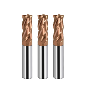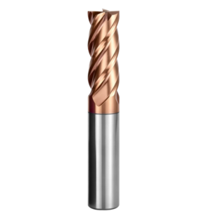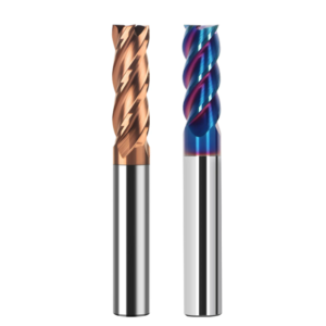
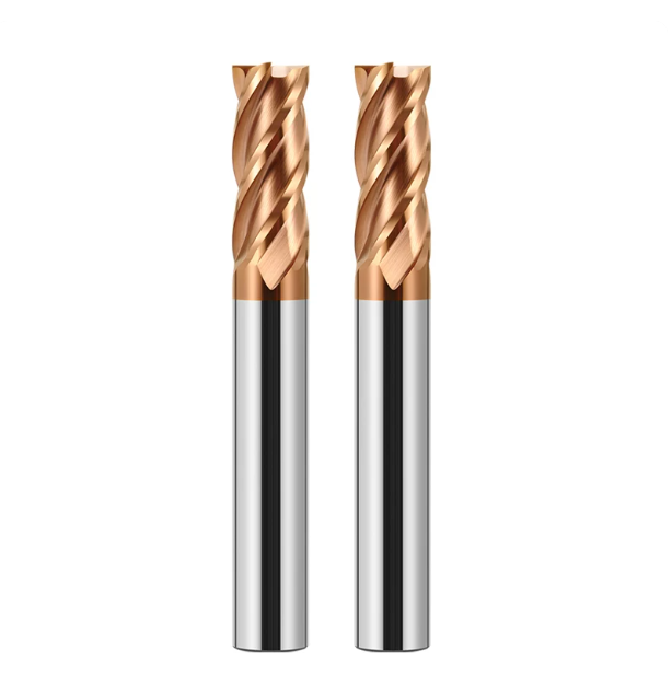
Last week, we reviewed tool scrap logs from a German die shop cutting heat-treated Sverker 21 (D2 equivalent at HRC 62–64). Their machine setup was solid: spindle runout under 2μm, rigid fixturing, and high-pressure air blast. Yet their 10mm four-flute flat tools developed micro-cracks within 20 minutes of high-speed side milling, followed by catastrophic tool snap. The customer assumed the coating had poor heat resistance or the carbide grade lacked impact toughness.
In our sixteen years supporting mold makers across North America and Europe, we have seen this failure cycle countless times. Under a stereomicroscope, fracture faces tell a very different story: the root cause is rarely the material grade. The real culprit is almost always tool geometry—specifically the HRC65 end mill core diameter.
Hardened tool steels above HRC 60 have virtually zero plastic yield. Radial cutting forces spike exponentially on contact. Many shops still run standard carbide end mill tools with thin webs (50% to 55% of outer diameter) to clear chips. Under heavy side load, that thin core lacks the bending stiffness to resist deflection. Microscopic flex sparks severe end mill chatter and vibration, causing instant micro-chipping and catastrophic failure.
Conversely, pushing the web past 75% creates a different bottleneck. The core becomes rigid, but shallow flute valleys cannot evacuate incandescent, hardened chips. Chips pack tightly in corners, recut against the relief faces, and trigger explosive tool failure. Finding the sweet spot between cross-sectional stiffness and chip evacuation is the decisive factor for end mills for hardened steel CNC operations.
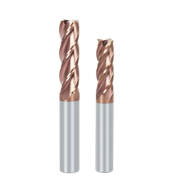
The Fatal Imbalance in Milling Hardened Steel: Why Do Standard Carbide End Mills Fail Prematurely?
When machining hardened tool steels, many machinists simply grab a standard carbide end mill from the tool crib. The common assumption is straightforward: drop the cutting speed, trim the feed per tooth down to a few microns, rely on a tough heat-resistant coating, and let it run. However, once you cross the HRC 60 threshold, that baseline logic breaks down. Standard geometry assumes the workpiece still yields plastically during chip formation.
Quenched tool steels have virtually zero ductility, causing unit cutting resistance to spike exponentially. Because general-purpose mills sacrifice web thickness for chip clearance, the tool tip deflects radially under load. The cut immediately shifts from crisp shearing into severe compressive rubbing. Friction spikes the cutting zone temperature within seconds, replacing clean cutting with high-frequency resonance and rapid edge destruction.
Field Analysis for a Western Client: End Mill Breakage in Hardened Steel—Often a Core Diameter Issue, Not a Coating Failure
Last year, we troubleshot a stamping run for an automotive die supplier in Michigan running Caldie inserts at HRC 62. They ran an 8mm flat end mill and saw severe edge flaking within 15 minutes, followed by total fracture at the flute runout. Their engineering team assumed thermal coating spalling was the cause and requested upgraded nanocomposite coatings.
Our metallographic inspection told a different story: the primary flank showed almost no abrasive wear. The fracture lines originated squarely at the flute root, where stress concentrations peak. Section measurements showed a web ratio of only 56%. This classic end mill breakage in hardened steel was not caused by coating failure, but by excessive flexural deflection that altered the effective chip load and snapped the teeth.
Cutting Forces and Deflection in Hardened Steel: The Exponential Impact of Core Rigidity on Bending Strength
To understand tool behavior in hardened steel, you must treat the mill as a cantilever beam. Machinists know thicker tools chatter less, but few realize how sensitive deflection is to cross-sectional area. Tool deflection under radial load is inversely proportional to its area moment of inertia. In practical terms, end mill core rigidity scales directly with the fourth power of the core diameter.
In our tool grinding designs, bumping a 10mm end mill’s core from 55% (5.5mm) to 68% (6.8mm) more than doubles its bending resistance. That stiffness jump holds cutting edge deflection to sub-micron levels, stopping cyclic chatter before it starts. The engineering trade-off is clear: gaining extreme body rigidity requires aggressive flute polishing and specialized core transitions to prevent catastrophic chip packing.
The Optimal Core Diameter Range for Milling HRC65 Mold Steel: Balancing Flute Volume and Tool Rigidity
Grinding tools for HRC65 mold steel is a tightrope walk. After breaking tools, many mold makers demand one thing: “Make the core as thick as possible so it stops snapping.” In practice, over-thickening the core merely trades one failure mode for another. Tool rigidity and chip room are physically opposed. As workpiece hardness climbs, your margin for error shrinks to near zero.
At HRC65, chips cannot carry away cut heat. If restricted flutes clog within two revolutions, concentrated thermal stress quickly softens the carbide substrate. You cannot simply maximize structural mass. Tool designers must hit a balanced window between bending stiffness and open chip channels, creating an optimized hardened steel end mill that survives continuous dynamic cutting.
The 65%–72% Core Diameter Ratio: Our Practical Design Benchmark for End Mills for Hardened Steel
On our 5-axis CNC tool grinders, we set the web thickness between 65% and 72% of tool diameter for hardened dies. We rarely drop below 65%. Under that threshold, normal edge wear causes micro-deflection, leaving visible wall waviness. Ratios near 70% to 72% belong strictly on finishing walls with large axial depths (Ap) and tiny radial step-overs (Ae) under 5% of tool diameter.
While engineering end mills for hardened steel CNC for a European die caster, we ran head-to-head trials between 68% and 74% cores. Running HRC 64 D2 steel along identical trochoidal paths, the 74% core was rock-solid on straight walls. However, chips packed in tight corner radii and wedged the tool. The 68% core version cleared every corner cleanly and lasted twice as long.
Chip-Evacuation Jamming Caused by Excessive Core Diameter: Preventing Sudden Tool Fracture from “Secondary Chip Cutting” in End Mills for Hardened Steel
When flutes snap, machinists often assume the feed per tooth was too heavy. In reality, workpiece scratch marks and chip debris point to secondary chip cutting. Hardened chips are brittle and red-hot. If chips cannot escape the flute, they get dragged under the following tooth. This sudden steel-on-steel pinch creates extreme point loads that shatter the cutter instantly.
To prevent chip jamming on a large-core hardened steel end mill, we abandoned flat flute floors. We grind parabolic, compound-curve flute pockets that steer micro-chips away from the web immediately. On the machine, aim your air blast nozzle directly along the flute roots. High-velocity air must physically blow glowing micro-chips out of the cut before the next tooth hits.
Flute Polishing and Variable-Geometry Cutting Edges: Key Geometric Features for Suppressing End Mill Chatter and Vibration
A thick core alone cannot stop resonance. When cutting edges strike hard steel at fixed time intervals, harmonic vibration destroys the tool edge. In our 4-flute tools, we combine unequal index spacing with variable helix angles. Staggering tooth impact breaks harmonic feedback loops, eliminating end mill chatter and vibration and turning high-pitched screeching into a dull cut hum.
Flute floor roughness is another major friction point. After grinding flutes, we use drag finishing and micro-polishing to buff out grinding wheel lines, dropping flute roughness below Ra 0.1μm. This mirror finish prevents hot chips from welding to the web pocket. The flutes stay slick and open, even during hours of unattended dry milling.
Core Diameter Strategies for Long-Reach End Mills in Deep-Cavity Machining
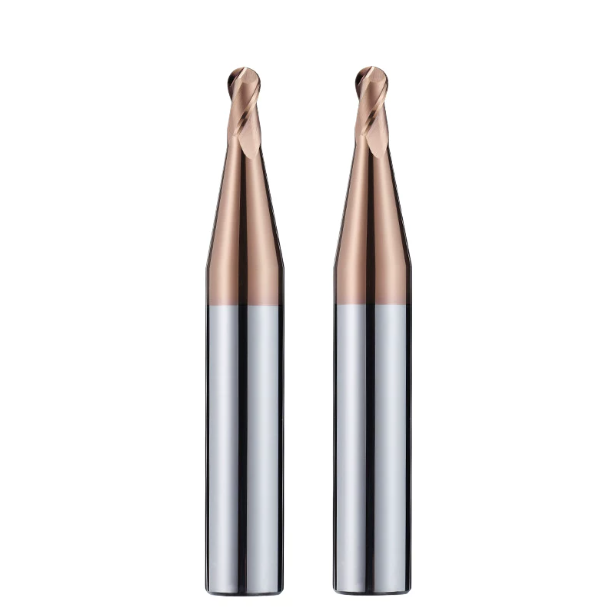
When milling deep cavities or tall ribs, tool stability drops fast once overhang exceeds 3D. To clear tall walls, many shops pick straight, small-neck tools from a catalog. However, tool tip deflection scales with the cube of overhang length (L^3). In HRC65 steel, minor side thrust causes high-frequency whip in slender necks, chipping the cutting edges immediately.
Merely thickening the flute core does not solve this problem, because bending stress shifts backward to the relieved shank. When engineering core diameter for long reach end mills, you must balance the cutting flutes and the tapered neck as one mechanical system. Maximizing cross-sectional stiffness while clearing part walls is mandatory for deep hard milling.
Stepped Tapered-Neck Design for Overhangs Exceeding 3D: Vibration-Damping Solutions for Long-Reach End Mills
For overhangs reaching 4D to 6D, scrap straight-neck designs entirely and switch to stepped taper profiles. We grind a 1.5° to 3° blend angle from the shank down to the flutes, while maintaining a rigid 68% to 70% web at the tip. This tapered root shortens the bending moment arm, boosts rigidity, and shifts the tool’s natural resonant frequency away from spindle harmonics.
A Swiss medical mold maker struggled with wall chatter while cutting 28mm-deep slots in hard steel. Their straight-reach tool flexed visibly in corners. We rebuilt their tooling around an optimized core diameter for long reach end mills featuring a compound taper neck, boosting root bending stiffness by nearly 80%. They held their 0.03mm radial cut at full RPM, keeping corner deflection under 3μm.
Deep Milling with Small-Diameter Tools: Optimizing the Transition Between Neck and Core Diameter to Extend End Mill Tool Life in Hardened Steel
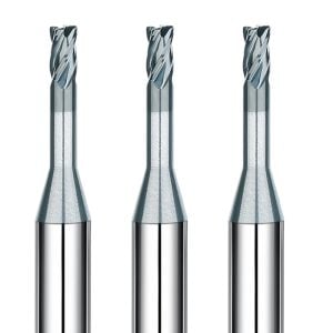
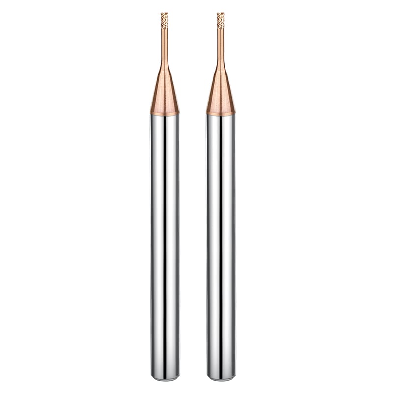
On miniature tools under 2mm, cutters rarely break at the tip or shank. Breakage usually strikes at the neck runout where the flutes end. Under a toolmaker scope, rough grinding wheel pullout creates sharp notches. These sharp transition shoulders act as stress risers, concentrating bending loads until cracks tear through the carbide.
A French connector mold shop had 2mm ball nose mills snapping after only three parts in HRC 64 powder metal steel. We replaced the sharp flute runout with an R0.3mm tangential blend radius, smoothly tying the flute core into the neck body. Eliminating that notch stress doubled end mill tool life in hardened steel, jumping tool life from 3 to 11 finished parts per tool.
A Practical Solution for Extreme Conditions Where Standard Tools Fall Short: Custom Carbide End Mills
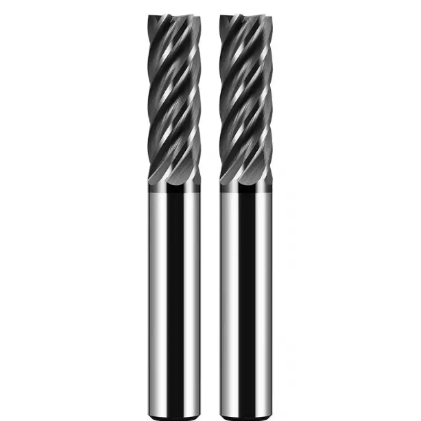
Machining HRC65 mold steel requires a relentless balance between deflection, chip evacuation, and thermal load. Standard catalog tools represent the lowest common denominator for generic jobs. In deep cavities, tight wall clearances, or close tolerances, off-the-shelf cutters fail. You either get enough rigidity with jammed flutes, or good chip evacuation followed by snapping.
If adjusting your feed, speed, and stick-out still fails to stop vibration or edge chipping, engineering a custom carbide end mill provides the cleanest solution. Customizing the core ratio, substrate grain structure, and flute transitions redistributes mechanical stress. This matches the tool directly to your part geometry, letting you push your CNC equipment to its true operational limits.
From Substrate Grain Size (0.2–0.4 μm) to Custom Core Geometry: Balancing Toughness and Rigidity in Custom Carbide End Mills
Core geometry resists bending, but microscopic substrate structure prevents brittle catastrophic fracture. When designing cutters for high-hardness milling, we select ultra-fine tungsten carbide blanks (0.2 to 0.4 μm grain size) with 8% to 10% cobalt. This metallurgical balance maintains high hardness (HRA 92–94) while preserving the fracture toughness required to absorb hard-milling shock loads.
If you are seeing persistent chipping on hardened steel die blocks, evaluate your tool substrate alongside core thickness. A high-performance custom carbide end mill pairs sub-micron grain carbide with a 68% reinforced core and compound back-off lands. This setup suppresses micron-scale deflection at the tool tip while reinforcing grain-boundary strength, ensuring the cutting edge resists shear flaking under extreme side loads.
Recommended Shop-Floor Cutting Parameters: Formulas for Radial Step-Over (Ae) and Axial Depth of Cut (Ap) for Hardened Steel End Mills
Switching to a thick-web cutter demands an updated programming strategy. Machinists run into trouble when they take traditional heavy radial cuts that overwhelm narrow flutes. With a large-core hardened steel end mill, we follow a strict low radial width of cut (Ae) and high axial depth of cut (Ap) dynamic milling strategy:
- Radial step-over (Ae): Run 2% to 5% of tool diameter (D) to minimize the contact arc and keep heat inside the chip.
- Axial depth (Ap): Push to 1.0$D$–1.5$D$ to distribute wear evenly along the cutting flutes.
- Feed per tooth (Fz): Hold 0.03 to 0.08 mm/tooth to ensure true chip shear and prevent abrasive edge rubbing.
Every hard-milling setup carries unique variables, from holder balance and machine taper rigidity to pocket entry angles. If you are struggling with chipped corners, chatter marks, or premature breakage on HRC 60+ dies, reach out to review your setup. Share your part prints, workpiece material grades, and current feeds and speeds so we can troubleshoot your tool geometry together.