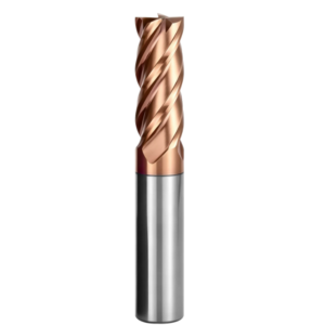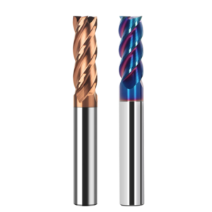

Last month, we helped a precision injection mold shop in Bavaria resolve a costly line stoppage. They were side-milling 1.2379 (D2) tool steel inserts hardened to 64–65 HRC on a five-axis machine. Spindle runout was held under 2 μm, and feeds matched industry standards. Yet, every new cutter suffered edge fracture in under 18 minutes, marring the workpiece surface with micro-scratches.
The shop supervisor suspected poor transverse rupture strength in the carbide grade. Under our shop microscope, however, the real flaw became obvious: the tooling vendor had applied a standard 50 HRC relief geometry to an ultra-hard application. The HRC65 end mill relief angle was ground far too steep, stripping the micro-wedge of its structural support under heavy radial load.
Over the past decade supporting toolrooms across North America and Europe, we have seen this setup error recur constantly:
- Too conservative (<4°): Intense elastic recovery forces the flank face to drag against the hardened workpiece. This traps severe frictional heat, leading to rapid thermal softening and accelerated carbide end mill wear.
- Too aggressive (9°–11°): Thinning the wedge angle beneath the edge leaves the carbide vulnerable. When striking hard eutectic carbides in 65 HRC steel, the micro-edge suffers shock-induced shear fracture, triggering catastrophic end mill cutting edge chipping.
Milling 65 HRC mold steel demands more than an off-the-shelf catalog tool. It requires a 0.5-degree geometric balance between cutting edge mechanical strength and flank friction resistance.
When tackling 65 HRC stock, is your shop trading away edge rigidity for perceived sharpness—or absorbing hidden downtime from severe flank friction?
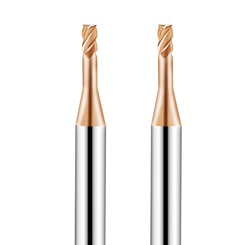
Why We Advise Against General-Purpose Relief Angles: The Root Causes of End Mill Failure in 65 HRC Hardened Mold Machining
In our field consultations, we frequently see experienced machinists rely on standard catalog end mills for hardened workpieces. Once steel hardness pushes past 60 HRC toward 64–65 HRC, plastic deformation virtually disappears. The cutting mechanism shifts from clean chip formation to high-pressure shear and micro-fracture. A tool that cuts smoothly in 50 HRC pre-hardened stock will often whistle and chatter within minutes in this extreme hardness bracket.
Generic geometries feature broad clearances suited for softer materials, but they fail under massive cutting pressures. When applying an HRC65 solid carbide end mill to deep cavities or thin ribs, cutting forces rise exponentially. At this hardness level, selecting a relief angle is never an off-the-shelf decision. You must balance the relief angle against your specific machine rigidity, spindle runout, and actual radial step-over.
A Common Pitfall: How Excessive Relief Angles Lead to Cutting Edge Chipping
Shops new to hardened mold steel often assume that larger relief angles ensure freer cutting and lower heat. We witnessed this firsthand at an automotive stamping die plant in Ohio running 1.2379 guide slides. Operators reported highly unpredictable tool performance, with cutters failing anywhere between 3 and 15 minutes into a run. Under our stereo microscope, the failure revealed ragged shell-like fractures rather than predictable abrasive flank wear.
This damage pattern is directly tied to an oversized end mill relief angle. Every extra degree of clearance removes one degree from the supporting wedge directly beneath the edge. When the cutter strikes hard eutectic carbides, the unsupported edge behaves like a brittle cantilever beam. The alternating shear stress causes rapid fatigue cracking, culminating in sudden end mill cutting edge chipping.
Compressive Friction and Thermal Stress Accumulation: How Insufficient Relief Angles Exacerbate Flank Wear
Conversely, grinding an overly narrow clearance angle creates subtle yet destructive problems. During a finishing pass at a medical mold maker in Italy, the cutter ran quietly without chatter. Yet by the twentieth minute, the spindle load gauge began to climb steadily, and cavity wall dimensions drifted out of spec. Inspecting the tool revealed an unbroken edge, but the flank face displayed a heavy friction wear land over 0.25 mm wide.
This failure stems from the intense spring-back effect typical of 65 HRC steels. When the clearance is too narrow, the tool cannot clear the rebounding metal. The flank face turns into a friction block running completely dry. Cutting zone temperatures rapidly exceed 800°C, breaking down the coating and triggering accelerated carbide end mill wear across the primary flank land.
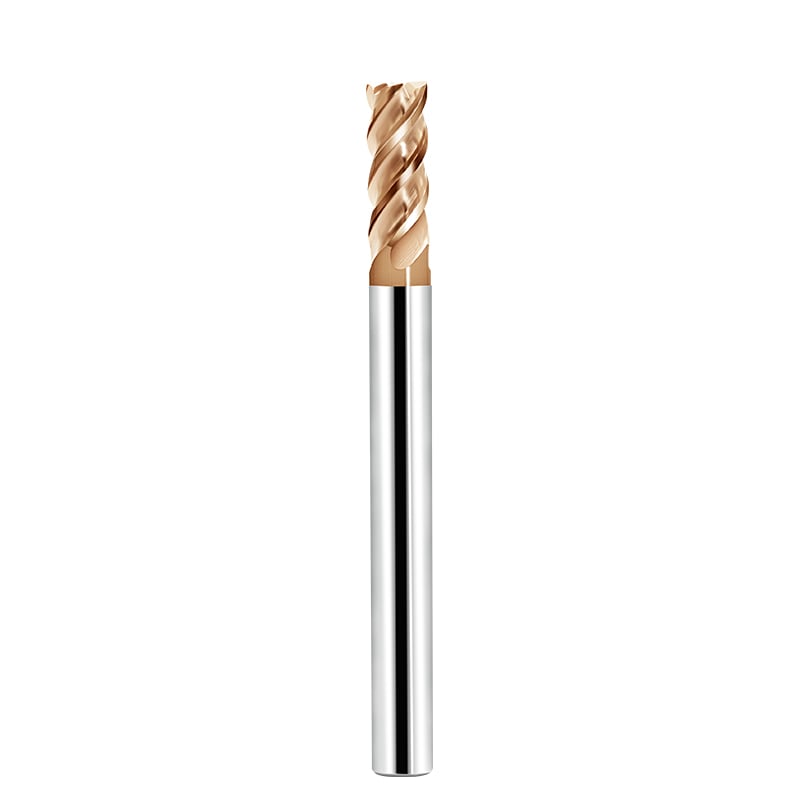
Balancing Core Geometric Parameters: Calculating Cutting Edge Strength and Design Trade-offs for Carbide End Mills Used on Hardened Steel
When milling materials above 60 HRC, we never design relief angles in isolation. In high-hardness cutting, the micro-region along the edge endures alternating compressive stresses exceeding several gigapascals. During tool development for a Swiss watch-mold maker, we saw this dynamic firsthand. Once steel hardness reaches 65 HRC, cutting forces shift heavily toward the center of the tool body, turning minor geometric transitions into severe stress risers.
Developing a reliable carbide end mill geometry for hardened steel requires balancing edge rigidity against flank clearance. We must preserve enough wedge angle volume to direct heavy cutting loads into the solid carbide core. At the same time, flute gullets and transition radii must clear chips cleanly. This balance is not a textbook formula; it is a practical compromise driven by radial step-over, dynamic chip load, and machine rigidity.
Optimizing the Match Between Primary and Secondary Relief Angles and Controlling Tolerances in Practice
Customers often ask why we avoid grinding a single flat relief on hard-milling cutters. Production data from our five-axis grinding centers proves that a single angle cannot support the edge while providing clearance. If the entire flank uses a conservative 5° angle, flank wear past 0.15 mm causes friction to surge, immediately scorching the cutting zone. Grinding a wide 10° clearance does the opposite, leaving the edge as thin and fragile as a razor blade.
We solve this using a dual-relief profile. We grind the primary end mill relief angle to 5°–6° to back up the cutting edge, followed immediately by an 11°–13° secondary relief to clear the workpiece. Production tolerances are held strictly: primary land width must measure 0.08–0.12 mm, with total edge runout held under ±0.002 mm. A wider primary land generates destructive friction heat, while an overly narrow land triggers chipping under load.
Combining Negative Rake Angles and Edge Honing (K-land) with Relief Angles for Machining HRC 65 Materials
If you examine our tools for 65 HRC powder-metallurgy steel under magnification, you will notice the edge is never razor-sharp. In hard machining, controlled micro-bluntness creates macro-stability. We grind radial rake angles to a negative -8° to -12°, often adding a micro K-land. This setup redirects cutting forces into pure compressive stress, playing directly to tungsten carbide’s natural load-bearing strengths.
A negative rake angle cannot succeed alone; it must coordinate with a dialed-in HRC65 end mill relief angle and precise edge preparation. We avoid coarse blasting and instead use brush polishing to hone an edge radius of 8–12 μm. This micro-radius transitions smoothly into the 5° primary relief, forming a rigid mechanical arch. Rather than brittle impacts, the edge shears the hardened steel smoothly, stopping micro-fractures before they start.
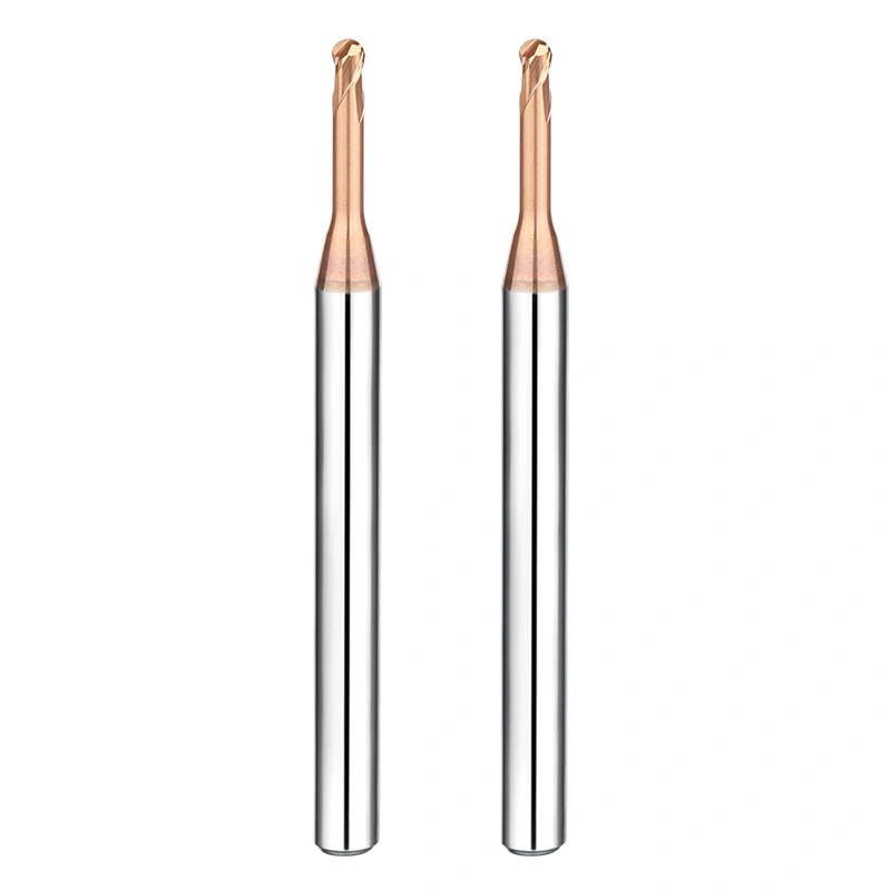
Optimizing Cutting Edge Micro-Geometry: Key Details in HRC65 End Mill Edge Design to Combat Chipping and Premature Failure
Under a 500x digital microscope, a cutting edge is never a flat line. It is an active 3D surface filled with micro-features and binder phases. When troubleshooting tool failure on 65 HRC dies, many engineers blame spindle speed or coating grade while overlooking edge topography. In our shop visits, perceived tool inconsistency usually traces back to a mismatch between cutting edge micro-geometry and the plastic flow of hardened steel.
Long tool life under high loads depends on micro-finishing the HRC65 end mill edge geometry. Extreme cutting temperatures cause abrasive wear from hard matrix carbides. If the cutting edge carries micro-cracks or grinding burrs, cutting loads quickly propagate those flaws into catastrophic failure. Micro-optimization builds a structural buffer into the carbide substrate by eliminating grinding marks while keeping cutting forces manageable.
Dynamic Impact-Resistant Design of End Mill Cutting Edge Geometry for Rough Milling and Deep Cavity Corner Clearing
Tool loading differs drastically between rough milling and clearing deep corners. While assisting a Swedish connector mold shop with 45 mm deep cavity work, we saw cutting edges fail rapidly once tool overhang passed 4xD. Cantilever vibrations subjected the edge to harsh, hammer-like impacts. Standard flute spacing and fixed helix angles quickly matched spindle frequencies, causing premature edge fatigue.
To stop this resonance, we re-engineered the end mill cutting edge geometry for dynamic damping. We combined unequal pitch spacing with variable helix angles to disrupt harmonic chatter. At the same time, we ground a dual-arc transition between the peripheral cutting edge and the corner radius. This profile spreads combined radial and axial cutting loads smoothly along the edge, preventing localized stress spikes at the corners.
The Actual Impact of Coating Thickness (AlTiN/Si-based Nanomultilayer) on Micro-Relief Angle Sharpness and Substrate Adhesion
Machinists often assume that thicker coatings guarantee better tool life, routinely asking for thicknesses over 4–5 μm. On 65 HRC hardened steel, thick layers often cause harm. When testing tools for a French stamping die manufacturer, thick PVD coatings created droplet build-up and edge round-off. This rounding blunts the edge profile and clogs the narrow primary clearance, undermining the intended clearance angles.
For steel up to 65 HRC, we specify ultra-thin (1.5–2.5 μm) AlTiN or silicon-doped (AlCrSiN) nano-multilayer coatings. In dry cuts exceeding 1000°C, silicon coatings form an amorphous, glass-like barrier with exceptionally low friction. At roughly 2 μm thick, this coating preserves your micro-honing and primary end mill relief angle. You achieve strong adhesion and heat shielding without the flaking risks that accelerate flank wear.
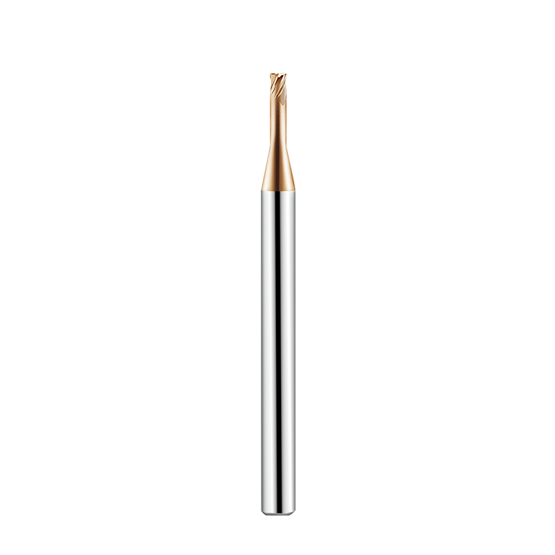
Workshop Test Data: The Impact of Relief Angle Fine-Tuning on the Tool Life of Carbide End Mills for Mold Steel
Discussing relief angles without accounting for machine rigidity and material grades is meaningless on the shop floor. To build reliable data for a European stamping die maker, we ran hundreds of hours of destructive side-milling tests. We mounted ultra-fine-grain cutters in shrink-fit holders on a high-speed Mikron machining center, cutting 1.2379 tool steel hardened to 64–65 HRC. We held coolant, runout, and carbide grades constant; the cutting edge relief angle was our only variable.
The resulting wear curves confirm that adjusting clearance by just 1° to 2° exerts a massive leverage effect on overall end mill tool life. In extreme hardness, no universal angle exists. Every degree ground into or off the clearance land represents a direct trade-off between edge impact strength and flank friction resistance. These subtle, data-driven modifications are what ultimately protect dimensional tolerance and process repeatability.
Tool Life Comparison—8° Standard Relief Angle vs. 5°–6° Reinforced Relief Angle in Continuous Side Milling of 65 HRC Mold Steel
Our side-milling test pitted an industry-standard 8° single relief against our optimized 5.5° reinforced profile. The reinforced design used a 0.10 mm primary land backed by a 12° secondary relief on a carbide end mill for mold steel. At the 25-minute mark of continuous dry milling, the performance curves split sharply. The 8° cutters suffered continuous micro-shelling along the peripheral edge, losing geometry and halting the run at 32 minutes due to severe chatter.
The 5°–6° reinforced profile showed a 3% to 5% higher spindle load early on due to tighter flank contact. However, the extra carbide mass provided crucial structural backing. It suppressed fatigue cracking from alternating shear loads, converting rapid chipping into predictable, uniform flank abrasion. Tools with the reinforced profile achieved over 75 minutes of stable cut time—delivering 2.3 times the working life of standard designs.
Feed per Tooth (fz) and the Critical Cutting Thickness: Calibrating Parameters to Prevent Excessive Flank Wear and Stabilize Relief Angles
Machinists tackling 65 HRC steel often drop the feed rate out of fear, pushing feed per tooth (fz) below 0.01 mm. This habit is a silent killer of cutting edges. Hardened steel exhibits high elastic recovery during shear, while the cutting edge carries a honed radius around 10 μm. If chip thickness falls below this elastic limit and honing radius, the edge stops cutting and begins severely rubbing the workpiece.
In our shop calibrations, we keep feed per tooth locked within a safe 0.025–0.045 mm/z window for 6 mm to 10 mm tools. Provided machine rigidity permits, you must force the edge to bite into the stock and generate discrete micro-chips. This dynamic clearance allows the HRC65 end mill relief angle to function properly, preventing the flank face from being crushed and frictionally annealed by rebounding material.

A Tooling Engineer’s Troubleshooting Guide: Identifying Wear Patterns to Optimize Relief Angles for 65 HRC Machining
When inspecting a failed cutter on the shop floor, never swap carbide grades on raw intuition. Cutting failures leave precise physical signatures. Every design choice—from dual-relief land widths and negative rakes to maintaining feeds above the elastic recovery limit—must be verified through physical wear patterns. Reading the edge under magnification replaces guesswork with actionable geometric adjustments.
Troubleshooting always begins by removing the tool to inspect whether the HRC65 end mill relief angle is in balance with your cutting loads. Reading the flank face tells you whether you are dealing with thermal annealing from insufficient relief or mechanical fatigue from an unsupported wedge. Identifying this distinction allows you to apply precise geometric offsets to your next tool order or regrind program.
Analyzing Wear Zones Under a Microscope: Distinguishing Normal Flank Wear from Spalling Caused by Micro-chipping
Under shop-floor lighting, operators often mistake all edge discoloration for standard wear, leading to incorrect tool corrections. We strongly advise inspecting pulled tools under an industrial digital microscope at 50x magnification minimum. Normal wear appears as a smooth, uniform, and slightly striated wear land along the cutting edge (VB held within 0.10–0.15 mm). The coating erodes steadily without shock fractures in the underlying carbide substrate.
If you observe jagged notches and conchoidal shell-like fractures along the edge, micro-fracturing occurred before any abrasive friction took place. This spalling indicates that the clearance angle is too open or the wedge lacks bending support. If you are experiencing sudden edge fracture, reduce your primary clearance by 1° to 1.5° and restrict your primary land width to 0.10 mm maximum, using the carbide mass to block impact forces.
Adjusting Clearance Angles and Compensating for Runout Based on Machine Tool Rigidity (BT30 vs. HSK63)
Identical tool geometries yield vastly different outcomes depending on spindle and holder rigidity. We regularly see clients using light BT30 high-speed machines for fine cavity clearing, while others run rigid HSK-A63 five-axis centers for heavy profiling. The lower radial rigidity of a BT30 taper yields under cutting loads, inducing dynamic deflection. Once dynamic runout passes 3 μm, individual flutes absorb heavy impact spikes, causing premature edge chipping.
Relief angles must adapt dynamically to your machine setup:
- If you are running BT30 or BT40 spindles on 64–65 HRC steel and struggle to hold runout under 2 μm, choose a conservative 4.5°–5° primary clearance. You accept slightly higher cutting forces to gain critical impact resistance.
- If you are running rigid HSK-A63 shrink-fit holders with dynamic runout held strictly within 1–2 μm, open the primary relief to 6°–6.5°. The wider gap cuts frictional heat, letting you maximize surface speed and overall end mill tool life.
Machining hardened steel requires tight alignment between machine rigidity, toolholding, and micro-geometry. If you face persistent edge chipping or dimensional drift in 60–65 HRC mold steels, reach out with your part drawings, material specs, and setup details. We are always ready to analyze the application and tailor the right cutting edge micro-geometry for your shop floor.