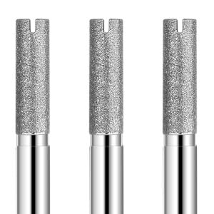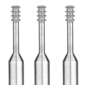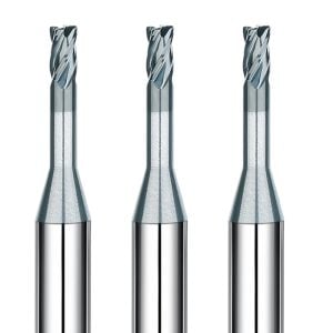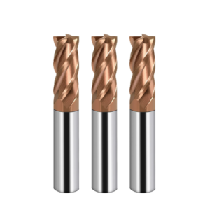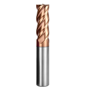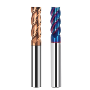
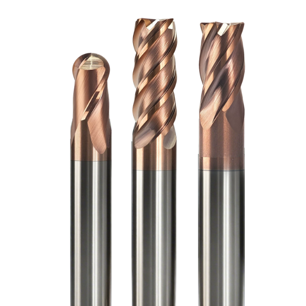
Three months ago, a tool-and-die shop in Baden-Württemberg, Germany reached out to us with an urgent spindle issue. They were finishing 1.2379 (D2) inserts hardened to HRC 64–65 on a 5-axis machine using an HSK-A63 interface. Just 18 minutes into the cut, their 4-flute end mills suffered severe micro-chipping, leaving fish-scale chatter marks across the sidewalls. The shop initially blamed coating delamination or machine tool rigidity. Under our microscope, the failure was not abrasive wear. It was mechanical edge chipping caused by an overlooked factor: the helix angle.
We see this blind spot constantly across US and European die shops. Machinists often default to a 45° or steeper high helix angle end mill because it works wonders on pre-hardened steels (HRC 40–50). But past HRC 62, heavy carbide precipitates drastically increase shear resistance. The cutting mechanism shifts from plastic shear flow to brittle fracture under extreme compressive stress.
At HRC 65, your priority must shift from chip evacuation speed to cutting edge integrity. A steep helix spikes axial pull-out forces, which can pull the shank straight out of a shrink-fit holder. More critically, high angles thin out the cutting edge wedge angle, starving the carbide substrate of backup support. Conversely, defaulting to a standard low helix angle end mill spikes radial forces, causing slender tools to deflect off nominal dimensions.
The cutting edge helix angle dictates how cutting forces split between radial push and axial pull during initial contact. It controls instantaneous impact shock and chip sliding friction. In the demanding realm of CNC milling hardened steel, which angle actually balances chipping resistance with cut stability? Are the chipped HRC65 end mill tools in your carousel really failing from bad feeds and speeds, or is your flute geometry working against you?
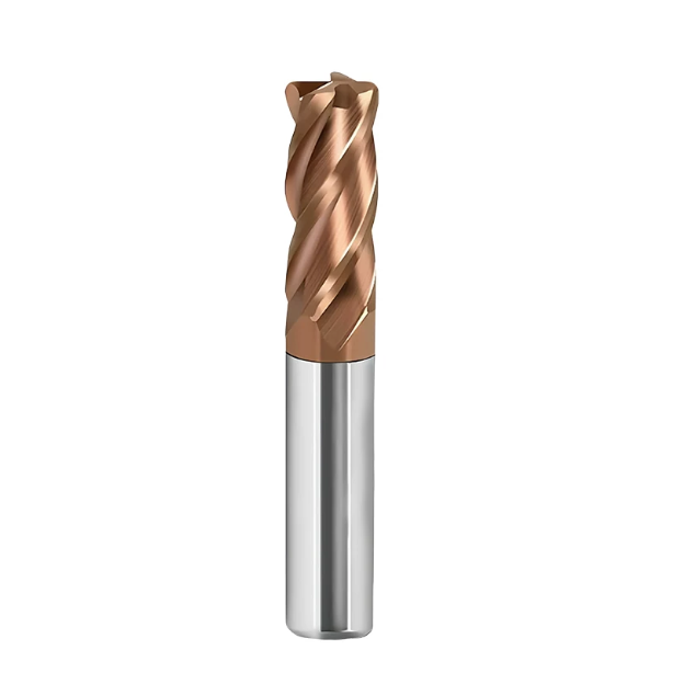
Why can’t the selection logic for end mill helix angles used for general steels be applied to milling HRC65 hardened steel?
Machining standard P-group alloys allows you to lean on high helix angles to dump heat and slide chips out fast. That logic fails the moment your workpiece hits HRC 65. The dense martensitic matrix and abrasive carbides generate extreme peak loads at the shear zone. Under these stresses, sharp cutting edges quickly become points of structural failure.
On-site troubleshooting has taught us that cutting HRC 65 stock is a continuous trade-off between edge chipping and tool deflection. Your primary goal must shift from low cutting drag to maximum carbide substrate support. If you ignore how end mill helix angle redistributes cutting forces, conventional tool choices will trigger sudden edge fracture every time.
The Core Conflict in CNC Milling Hardened Steel—Cutting Resistance vs Edge Chipping
Last year, an automotive die shop in Ohio asked us to diagnose persistent chatter on CPM 1V powder-metal inserts hardened to HRC 64–65. To lower spindle load and get a better surface finish, the programmer ran high-helix cutters rated for general steels. Within thirty minutes, micro-fractures spread across the corner radius and snapped the tool tips. The shop suspected bad feed rates, but the actual cause was tool geometry.
This scenario exposes the fundamental friction in CNC milling hardened steel. Zero ductility prevents the material from shearing into smooth, continuous chips. Instead, each flute absorbs a high-frequency shock pulse upon engagement. If you sacrifice cutting-edge core mass for a softer entry, high cutting resistance turns into stress waves that shatter carbide grains.
Force Decomposition in Carbide End Mill Geometry at HRC65: The Dynamic Trade-off Between Axial Force and Radial Resistance
Analyzing force vectors shows that flute helix directly splits cutting resistance into axial pull and radial push. In deep cavity sidewalls, shops hit a tough dilemma. Low angles increase radial push and cause wall taper. Meanwhile, steep angles send axial pull forces surging toward the spindle. In HRC 65 stock, that upward pull can overcome shrink-fit clamping and yank the cutter down.
Balancing your carbide end mill geometry requires practical compromises rather than chasing ideal textbook numbers. We prefer handling slight radial push with rigid tool holders and shallow-cut CAM routines. That approach avoids extreme axial pull-out and preserves wedge thickness. Keeping the micro-grain carbide in compression rather than tension is what prevents edge failure.
How the Cutting Edge Helix Angle Determines Instantaneous Entry Impact and Chip Shear Morphology
Entry dynamics depend heavily on how the rake face impacts the workpiece. A straight flute provides massive compressive mass, but its flat impact hammers the spindle. Adding a spiral creates a progressive, angled entry that softens initial impact. However, chips at HRC 65 do not flow naturally; they shatter into tight, jagged flakes under intense compression.
This behavior means your cutting edge helix angle pinpoints where frictional heat builds up. Steep flutes elongate the chip sliding path, accelerating crater wear that rapidly ruins the main edge. A milder angle increases entry pressure slightly, but it forces material removal into stable compressive shear. Combined with a micro-honed edge prep, it protects the cutting zone.

Key Performance of Low Helix Angle End Mill (30°–35°) in Roughing and Slotting HRC65 Mold Steel
When slotting or roughing HRC65 mold steel, shop floors dread that high-frequency spindle shriek. Cutting zone temperatures regularly blow past 800°C. At this hardness, the material has massive compressive strength but practically zero ductility. Across years of shop-floor validation, we have found that running a low helix angle end mill provides the safest compromise between tool rigidity and cutting resistance. It directs primary cutting forces into axial compression rather than destructive lateral bending.
A 30°–35° helix is not a cure-all, and it definitely compromises chip evacuation. But on high-volume roughing in closed pockets, steep helix angles generate axial pull forces that quickly destroy cutters. A low helix angle creates a broad structural foundation right behind the cutting edge. You need disciplined toolpaths and pressurized air blasts to run it, but it delivers predictable tool life under punishing cuts.
Flexural Rigidity and Edge Support Conferred by Low Helix Angles in End Mill for Hardened Steel
Programmers often evaluate core diameter while overlooking how flute twist weakens the tool’s actual section modulus. When manufacturing an end mill for hardened steel, a 30°–35° flute maintains a shorter rake path. This geometry preserves more ultra-fine micro-grain carbide along the tool core. The resulting mass gives the tool high static bending strength and torsional resistance.
Backing mass behind the cutting edge matters just as much. A lower helix angle widens the normal wedge angle of the cutting edge. That reinforced carbide base absorbs periodic entry impacts without micro-fracturing. Cutting stresses flow smoothly into the tool core, keeping the rake face from chipping under concentrated shear loads.
How Low Helix Angle Mitigates Radial Deflection and Micro-chipping in Hardened D2 and S7 Steels (HRC 60–65)
In Detroit, we helped an automotive die shop stop tool deflection on D2 and S7 slides hardened to HRC 62–65. The shop was running long-reach cutters on deep steps. This caused visible steps on bottom floors and micro-chipped cutting edges. We switched them to a rigid low helix angle cutter paired with dynamic trochoidal paths. Workpiece sidewall deflection dropped by over 60%, and the chipping stopped immediately.
The fix came down to vectoring cutting forces. D2 is loaded with massive, hard eutectic carbides that strike the tool tip like tiny hammers. High-helix tools snap back axially every time a flute exits, causing heavy load spikes. A lower helix produces stable radial force vectors instead. Paired with shrink-fit holders and rigid guideways, it prevents the tool from flexing and digging into the steel.
Chip Evacuation Limits and Pitfall Avoidance for 30° Helix Hardened Steel End Mill in Side Milling and Shallow Plunge Milling
Shop floors must recognize the physical chip evacuation limits of a 30° hardened steel end mill. Because the spiral is flatter, flutes lack the lifting action needed to eject hot chips vertically. Cutting HRC65 produces glowing, abrasive micro-chips that settle in the floor of the cut. If the tool re-cuts these trapped chips, the cutting edges fail in minutes.
To prevent re-cutting failures, blast the contact zone with dry compressed air at 0.6–0.8 MPa or run Minimum Quantity Lubrication (MQL). Never flood the cut with standard coolant, or thermal shock will crack the carbide. In CAM, drop full-width slotting in favor of trochoidal paths with modest axial step-downs. This ensures hot chips clear the flutes the instant they sheer off.
Can High Helix Angle End Mill (45°–50°+) Be Used on HRC 65 Materials? Application Limits and Pitfalls
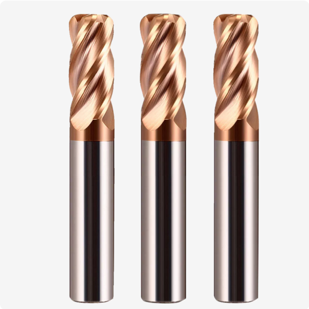
When an operator loads a 45° or 50° cutter into an HRC65 setup, we step in right away. High-helix flutes cut beautifully in aluminum and stainless, but on hardened tool steels, they behave like razor blades hitting granite. The sharp geometry enters the cut smoothly, but the micro-edge lacks the toughness needed to survive extreme mechanical shock.
Even so, banning every high helix angle end mill from hardened steel work is a mistake. You just need to respect their strict operational boundaries. Using them for roughing or pocket corners leads to instant scrap. But on light sidewall finishing passes with micron-level step-overs, their continuous shear dampens harmonics better than low-helix tools. Balancing finish against breakage risk is the entire trick.
Surface Quality Advantages of High Helix Angle End Mill in Hardened Steel Finishing: Real-World Data on Cutting Stability and Finish
At a medical mold plant in Zurich, a customer needed an Ra < 0.15 µm finish on powder-metal punches hardened to HRC 64–65. Hand polishing was forbidden to protect profile tolerances. Standard 30° end mills left faint step-over chatter marks on the sidewalls. We moved the final 0.02 mm skim pass to a custom 50° high helix angle end mill, dropping surface roughness to Ra 0.12 µm with flawless transitions.
That surface finish improvement comes from continuous edge contact. Long helical flutes keep multiple teeth engaged in the cut at the same time. This overlap prevents the intermittent impact marks typical of lower-helix cutters. On rigid spindles with sub-micron runout, a high-helix finisher removes the need for bench polishing.
Beware of Axial Pull-out Overload: High Helix Angles Can Cause BT40/HSK Tool Holder Pull-out and Upward Deformation of Thin-walled Parts
Surface finishes look great until steep helix flutes generate severe axial pull-out forces. We investigated a spindle collision where an operator ran a 45° end mill in a BT40 collet chuck on HRC65 stock. Cutting forces dragged the tool out by nearly 0.08 mm, ruining the die block. Steep flutes turn cutting drag into downward pulling forces that can overcome standard collet friction.
Workpiece deflection is just as risky. On thin ribs or unsupported walls, heavy axial lifting forces pull the workpiece upward, causing micro-warping and chatter. We advise mounting high-helix tools strictly in shrink-fit holders or hydraulic chucks with solid part fixturing. If toolholder grip or fixture rigidity is questionable, drop the helix angle and protect the part.
Mechanism of Cutting Edge and Rake Face Spalling: Why 45° Helix HRC65 End Mill Tools Are Prone to Instantaneous Failure at Corners
In deep cavity machining, the scariest sound is a sharp snap when an end mill hits an inside corner. SEM inspection of failed 45° HRC65 end mill samples reveals heavy conchoidal shell-like fracturing across the rake face. Steep helix flutes create thin wedge angles on normal cross-sections. That geometry robs the outer corner of carbide mass, leaving it unable to survive sudden lateral shocks.
When a 45° tool enters an internal radius, tool engagement spikes instantly. The load changes from a light side cut to a heavy pinch on multiple flutes. In unyielding HRC65 stock, friction heat cannot escape through the chips fast enough. Extreme shear stress concentrates on the thinned wedge, snapping carbide grains instantly. Keep tools over 45° off your tool list whenever cuts feature abrupt corner transitions.
Breaking Through Machining Bottlenecks: Tuning Insights for Unequal Helix HRC65 End Mill Tools
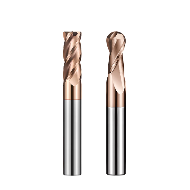
When fighting severe chatter in ultra-hard milling, machinists often drop spindle speed or axial depth with little success. At HRC65, constant-helix cutters strike the workpiece at fixed frequencies. If this excitation syncs with the natural frequency of your spindle or tool overhang, harmonic resonance destroys the edge. We combat this by grinding differential helix angles into the tool body, introducing a phase shift that breaks up harmonic amplification.
Our field experience across North American mold shops confirms that an unequal helix HRC65 end mill is the most reliable way past this hurdle. By varying the flute helix angles, each tooth enters the cut at a different interval, contact length, and force level. This asymmetrical force profile wipes out the physical triggers of regenerative chatter. Your machine maintains cutting stability even under severe setup overhangs.
Suppressing High-Frequency Harmonic Chatter: Performance of 35°/38° or 38°/41° Variable Helix Endmill Cutters in Deep-Cavity Hardened Steels
In Ontario, we helped an injection mold maker cut S-7 cavity inserts hardened to HRC 63–65 with a 4.5xD overhang. Standard 35° four-flute tools produced severe fish-scale chatter along the walls, while steep-helix alternatives chipped instantly. We swapped in a 35°/38° differential endmill. Spindle harmonics shifted immediately from a high-pitched scream to a low, stable hum, slashing sidewall waviness by over 70%.
For deep-wall side milling, a 35°/38° or 38°/41° split delivers the sweet spot between tool mass and dynamic damping. A split smaller than 2° cannot generate enough phase lag to kill resonance waves. Spread the difference beyond 5°, and uneven flute volumes create severe chip-packing imbalances that wear down individual teeth. A tight ~3° difference disrupts harmonic cycles while keeping radial loads evenly shared.
Maximizing Tool Life by Pairing Negative Rake Angles and T-Land Edge Prep with Cutting Edge Helix Angle
Adjusting flute geometry alone cannot stop cutting edge fracture in hardened die steels. The helix angle directs macro force vectors and breaks chatter phases, but microscopic grain strength depends on your edge prep. Once we calculate the correct cutting edge helix angle, we grind a -5° to -8° negative radial rake paired with a 0.03–0.05 mm reinforced T-land chamfer.
This edge prep fundamentally changes how metal shears away. The negative rake and micro-chamfer generate intense triaxial compressive stress right at the cut boundary. This forces the brittle HRC65 material to shear in localized high-pressure micro-burnishing rather than tensile chipping. Skipping this edge prep leaves razor-sharp carbide that crumbles against hardened tool steel within seconds.
Field-Proven Parameter Libraries Optimized for North American Mold Shops: Matching Ap/Ae, Feed Rate, and Helix Angle
When writing CAM programs for aerospace and automotive mold tooling, never carry over conventional toolpath habits. Cutting HRC65 stock demands high spindle RPM, shallow axial cuts, micro radial step-overs, and tight engagement angles. For 35°/38° tools, we keep surface speed (Vc) between 50–75 m/min and feed per tooth (Fz) around 0.015–0.03 mm. Micro-chipping feed rates keep heat from baking into the workpiece.
Radial step-over (Ae) must stay strictly within 2%–5% of the cutter diameter, while axial depth (Ap) runs 0.5–1.0xD based on tool stick-out. Running a micro-Ae shrinks the radial engagement arc, giving variable-helix flutes enough dwell time to cool and evacuate chips. Pair this with under 3 µm spindle runout and dry compressed air blasts to double your tool life.
How Do We Select the Optimal Helix Angle for an End Mill for Hardened Steel?
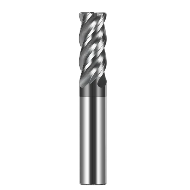
Helix angle selection cannot happen in a vacuum; it functions as a linked chain with spindle stiffness, tool holding, and toolpaths. When auditing customer setups, we select geometry based strictly on operating realities. At HRC65, material ductility vanishes and operating windows narrow sharply. Applying tooling assumptions meant for pre-hardened steels causes sudden, catastrophic tool breakage.
Maximizing tool life on hardened steels requires looking beyond chip evacuation or surface finish in isolation. You must keep combined cutting vectors within your machine’s mechanical limits. Choosing an end mill for hardened steel comes down to balancing radial deflection against axial pull. Aligning this balance with your roughing or finishing stage eliminates expensive trial-and-error scrap.
H3: Cavity Roughing, Corner Cleaning, and Sidewall Super-Finishing: Endmill Helix Angle Selection Matrix by Process Stage
If you are running high-volume roughing or trochoidal clearing in deep pockets, run a 30°–35° low-helix tool. Its thicker web and high cross-sectional stiffness easily take heavy cyclic shock loads. If you are semi-finishing long-reach walls or picking out tight corners, an asymmetrical 35°/38° endmill breaks up harmonic chatter. If you are mirror-finishing sidewalls with step-overs under 0.02 mm, a 45° tool delivers continuous shear damping.
This staged approach pairs specific tool geometry to the dominant cutting load of each operation. Roughing prioritizes core strength and deflection control, while finishing focuses on dampening tool vibration and eliminating surface witness marks. Running a high-helix finisher into an un-cleared corner spikes cutting loads instantly, shattering the delicate wedge angle.
The Impact of Machine Spindle Rigidity and Clamping Systems (Shrink-Fit vs. Power Collets) on Helix Angle Selection
Your machine spindle interface and holder style dictate safe limits for helix angles. If your shop runs BT40 tapers with mechanical power collet chucks, run conservative helix angles to prevent axial pull-out under heavy loads. If your machine features HSK-A63 spindles, short-reach shrink-fit holders, or hydraulic chucks with micron-level runout, you can safely leverage steeper helix angles for smoother shearing action.
Low system rigidity cannot absorb high axial pull forces. If your machine guideways lack dynamic stiffness or your workpiece has thin, unsupported sections, large helix angles pull the part upward and induce vibration. Under these conditions, lower helix angles direct cutting energy into rigid axial compression, creating a much wider process safety margin.
On-Site Checklist for Extending HRC65 End Mill Life: Identifying Abnormal Wear Caused by Helix Angle Mismatch
Establish a shop-floor microscopic inspection habit to pinpoint whether your tool geometry matches your cut. If you find shell-like conchoidal chipping across the corner radius right at initial engagement, your helix angle is likely too steep, leaving the wedge unsupported. If the edge remains intact but the tool deflects severely while chips weld inside the flute roots, you pushed a low-helix tool beyond its chip evacuation limits.
A properly matched HRC65 end mill should only show smooth, uniform flank wear bands at end-of-life—never sudden fracturing or shank slippage. Every mold pocket, heat-treat hardness profile, and setup stiffness presents unique challenges. If you are currently dialing in specific deep-cavity prints, unusual tool steels, or stubborn chatter issues, share your cutting parameters with our team so we can help fine-tune your tool geometry.