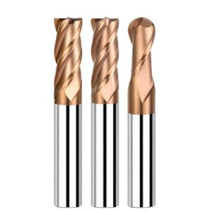
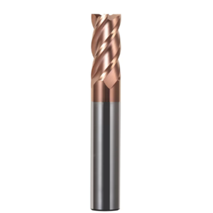
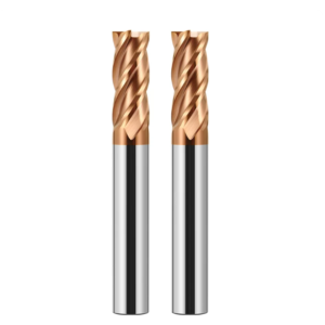
Two months ago, we worked on-site at an automotive stamping die plant in Stuttgart, Germany. The team was milling 1.2379 (D2) die steel heat-treated to HRC62 on a 3-axis high-speed machining center. The operator ran a traditional constant-Z waterline toolpath. The spindle emitted a high-pitch squeal, the cutter tip suffered constant micro-chipping in corners, tool life stalled at 35 minutes, and visible witness marks ruined the surface.
We encounter this exact situation all the time across European and US machine shops. When roughing HRC55 to HRC65 steels, programmers often default to shallow axial cuts and slow feeds. This forces the dead center of the tool—where cutting speed drops to absolute zero—to drag and burnish the steel. The resulting work hardening and intense friction will rapidly destroy even a premium carbide ballnose endmill.
The solution is not running slower feeds. You need to change the cutting force mechanics through dynamic CAM toolpaths. Specifically, this means adapting trochoidal and peel milling strategies directly to a ballnose endmill for hardened steel. Real shop-floor data confirms three reliable rules:
- Constant Engagement Angle Control: Traditional linear corners spike radial cutter engagement from 30° to 180°, causing extreme deflection. Trochoidal paths lock the radial cut width (ae) at 3% to 8% of the tool diameter, eliminating shock loads.
- Leveraging Chip Thinning for High MRR: At tiny radial step-overs, the actual chip thickness shrinks dramatically. Increasing the table feed compensates for this thinning, pushing thermal energy directly into the flying chips rather than the tool core.
- Eliminating Scallops with Peel Milling: High axial depths paired with micro-radial step-overs allow the peripheral ball radius to peel away stock smoothly. This yields finishes below Ra 0.4 µm and cuts out hours of manual bench polishing.
In our grinding shop, we run endless impact tests on flute cores and edge preps for hard milling tools. Even the finest sub-micron carbide and nanocomposite coatings will fail on hardened steel without the right toolpath kinematics. Are your tools really burning up because the steel is too hard, or is your CAM code driving the cutter tip into a brick wall?
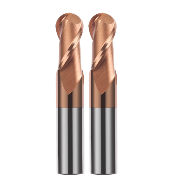
Why are mold shops in Europe and the US switching from flat-bottom end mills to carbide ball-nose end mills for post-hardening roughing operations?
For decades, toolrooms across North America and Europe roughed hardened tool steel using bull-nose or square-shoulder cutters. On complex 3D contours and steep draft angles, however, square corner inserts take brutal point-load shocks. This leads to edge chipping, premature corner blowout, and erratic tool life. Today, veteran programmers increasingly run a carbide ballnose endmill with trochoidal toolpaths to rough out hard cavities reliably.
Square end mills produce severe, step-like cutting force spikes. A continuous spherical radius, by contrast, eases the cutting edge into the cut with progressive tangential resistance. While square tools claim a higher theoretical metal removal rate, they cannot match the shock-free load transitions of a round profile above HRC58. Our shop-floor trials prove that ballnose roughing drops catastrophic tool breakage to near zero while drastically stabilizing spindle load.
H3: Solving Pain Points for a German Automotive Stamping Mold Client: From Abrupt Right-Angle Transitions to Constant Contact Angles
During our 2024 field run for the Stuttgart automotive mold client, we hit a classic bottleneck on HRC60 D2 steel. Every time the cutter entered a deep 90° corner, the spindle load surged from 35% to over 85%. The machine made an awful grinding moan, and one out of every three tools shattered in the turn. The operators blamed weak machine rigidity and kept lowering the feed rate.
The root cause was clear in the NC program: the toolpath went straight into the corner, spiking cutter engagement from 30° to a full 180°. We replaced the linear moves with smooth, looping trochoidal arcs that capped radial cutter contact at a constant 8%. Using the exact same ballnose endmill, the shock load vanished immediately, the chatter stopped, and the tool completed four straight hours of roughing with zero edge wear.
H3: Actual feed-per-tooth compensation formula derived from our workshop tests regarding the “chip thinning” effect
Many programmers run into trouble when they drop radial step-over (ae) down to 4% or 5% without adjusting feed. They use nominal catalog feed-per-tooth (fz) rates. At light radial engagements, the actual chip thickness is a tiny sliver. The cutting edge rubs and slips instead of shearing, generating extreme friction that strips the PVD coating within minutes.
To fix this, our testing center uses an effective feed compensation multiplier. For example, when running an 8mm ballnose endmill at a 0.4mm radial width of cut, you must more than double the programmed feed rate. This establishes a healthy, true chip thickness that absorbs the cutting heat and evacuates it away from the tool shank.
Why are ball-nose endmills designed for hardened steel so easily ruined by “excessive cutting heat” during trochoidal milling?
Machinists often ask us: if chip thinning lowers cutting temperatures, why do tool tips still blacken, burn, and fail during hard trochoidal milling? The answer comes down to cycle frequency. Trochoidal motions run dense, continuous high-speed arcs, keeping the tool in near-constant engagement. High-heat nanocomposite coatings help, but they cannot overcome poor chip evacuation.
When milling above HRC60, re-cutting trapped chips destroys your cutting edges. Work-hardened micro-chips act like carbide grinding grit inside the slot. What looks like simple abrasion under shop lights is almost always thermal fatigue cracking in the substrate. If you run a ballnose endmill for hardened steel, do not rely on flood coolant; blast dry, high-pressure air directly at the cut zone to clear chips instantly.
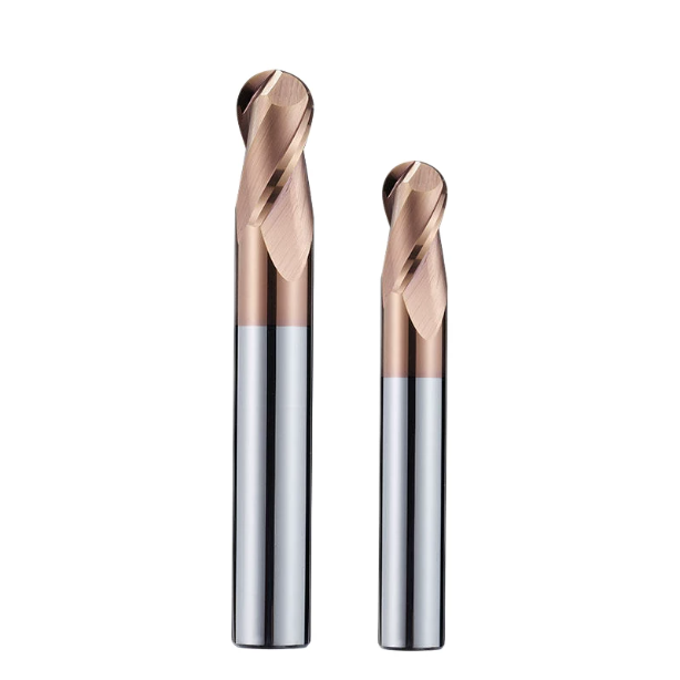
Mastering Hardened Mold Steels (HRC 55–65): Micro-geometry and Chip Evacuation Control for HRC 65 Ball-Nose End Mills
Machining vacuum-quenched hot-work or powder-metallurgy tool steels pushes cutting tools to their physical limits. Once material hardness passes HRC55, metal removal shifts from plastic shear deformation to micro-fracture extrusion. If you use general-purpose tools with standard rake profiles, high shear pressures will chip and delaminate the cutting edge in minutes.
Reliable hard milling depends on micro-geometry rather than macroscopic flute styling. A dedicated hrc65 ballnose endmill requires an ultra-fine sub-micron carbide substrate, an optimized core web, and a dialed-in honing radius. Operators often fixate solely on RPM and table feed, missing how micro-edge preparation dictates whether a cutting edge shears smoothly or crumbles under load.
Why do we use a slightly negative rake angle combined with a negative land (honing) when manufacturing HRC65 ball-nose end mills?
Customers frequently ask our tool grinders: “Why not sharpen the cutting edge more to lower cutting forces?” Our test rigs show that sharp, positive-rake edges experience high tensile stress when hitting hard carbide inclusions above HRC60. Cemented carbide handles compression well, but its tensile strength is poor. Under heavy tensile loads, sharp edges flake off like brittle glass.
When grinding our carbide ballnose endmill series for hard milling, we set the radial rake between -5° and -8° and apply a 5 to 10 µm edge hone. This negative rake profile converts sharp tensile forces into compressive stresses that the carbide core can absorb. It increases passive radial thrust slightly, but it keeps the cutting edge rigid and chip-free during aggressive roughing cuts.
Solving the challenge of clearing residual material in mold inner corners: How trochoidal paths prevent premature chipping at the ball-nose center (Zero-Speed Center)
In deep mold pockets, operators frequently notice a frustrating failure pattern: the outer flutes remain sharp, but the exact center tip breaks off and burns black. This happens because the cutting radius shrinks to zero at the ball tip, dropping surface footage to dead zero. The tool cannot shear material at the center; it simply crushes and smears steel under severe axial downforce.
We solved this for a European injection mold maker whose standard waterline paths rammed the cutter center straight into leftover corner stock. We reprogrammed the CAM file with convex trochoidal peel passes and added a minor tilt angle to keep cutting contact between 30% and 70% of the ball radius. Paired with a proper ballnose endmill for hardened steel, this shift eliminated tip blowouts and reduced corner tool breakage by over 80%.
Air cooling, oil mist (MQL), or dry cutting? Data on tool thermal fatigue failure from HRC62 die-casting mold tests
Coolant selection in hard milling sparks constant debate. In our testing lab, we conducted extended-wear trials on HRC62 1.2344 (premium H13) die-casting blocks. Running flood water-soluble coolant proved disastrous: the tool face hit 900°C in the cut and quenched instantly upon exit. This severe thermal shock cracked the cutting edge with dense comb fractures, destroying the ballnose endmill in under twenty minutes.
By contrast, running dry with clean, compressed air at 6 bar or higher produced smooth, predictable flank wear. High-pressure air ejects glowing chips instantly, preventing re-cutting scratches without thermal shock. For high-finish requirements, clean MQL (minimum quantity lubrication) reduces cutting friction nicely. Unless you must hold tight thermal limits across a huge part, dry air blast is far safer than flood coolant for hard trochoidal milling.
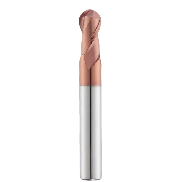
Practical Parameter Matching: Deep-Cut Guidelines for Various End Mill Sizes and Hardened Materials
When cutting hardened tool steel, many machinists run the catalog speeds and feeds stamped on the packaging. That works on pre-hardened P20, but it triggers instant chipping between HRC55 and HRC65. Hard milling is unforgiving of chip-load spikes; different cutter diameters have completely different core-to-OD ratios, transverse rupture strengths, and chip flute volumes. You cannot use linear scaling logic across different tool diameters.
When we dial in toolpaths for overseas shops, we program around tool body rigidity rather than catalog maximums. Large tools have high torsional stiffness to handle deeper axial cuts, provided radial step-over stays low to stop spindle harmonics. Micro-cutters have thin web cores where tiny feed spikes snap the neck instantly. Dialing in dynamic limits for specific end mill sizes is essential for true lights-out hard milling.
H3: Parameter Gradient Table Across Sizes: Limits for Trochoidal Step-over (ae) Settings—From Micro-Milling Cutters to Standard End Mill Sizes
Programmers often get into trouble when scaling step-overs down from medium tools to micro-cutters. On a 12mm tool, an 8% radial cut (ae = 0.96 mm) cuts smoothly in high-speed toolpaths. Take that same 8% ratio down to a 2mm or 3mm micro-tool, and the cutter snaps the second it touches the steel. Micro-flutes are shallow, so high chip loads choke the flutes and exceed the carbide’s shear limit.
In our testing center running HRC60 die steel, we cap radial step-over for micro-tools under 3mm at 2% to 4% of tool diameter. You want to generate surface footage through spindle RPM rather than taking a wider cut. Once you move up to standard carbide ballnose endmill sizes from 6mm to 16mm, you can open step-overs to 5%–8%. Finding this sweet spot beats chasing aggressive cut widths every time.
Why is the 8mm Ball-Nose End Mill the “Golden Threshold” for Deep-Cavity Roughing and Semi-Finishing in European and North American Injection Mold Manufacturing?
Walking the floor at high-precision toolrooms in Germany and the US, we noticed a consistent trend. The most stocked tool in the crib is almost never a rigid 10mm or an agile 6mm. It is almost always an 8mm cutter. This is an industry consensus balancing pocket geometry, tool stiffness, and toolholder clearance.
Mechanically, an 8mm ballnose endmill delivers nearly 2.3 times the bending resistance of a 6mm tool, dramatically reducing high-frequency chatter. Automotive lighting and appliance molds typically carry R4 to R5 floor fillets in deep ribs, making an 8mm cutter an exact fit for clearing rest stock. It balances the rigidity needed for aggressive cuts with 3D contouring reach, making it the safest workhorse for deep cavity work.
Compensating for Lateral Tool Deflection During Trochoidal and Peel Milling with Long-Overhang (4D+) 8mm Ball-Nose End Mills
Deep mold cavities beyond 35mm force long tool overhangs that amplify the cantilever effect. Running an 8mm ballnose endmill at 4xD or 6xD stick-out causes microscopic lateral deflection under radial cutting pressure. If your CAM path drives the theoretical wall profile on a deep finish cut, you get taper: the top of the wall undercuts while the floor retains excess stock.
We fixed this for a French aerospace mold maker using a three-step adjustment. First, drop radial width and table feed by 15% to 20% to reduce push-off force. Next, program stepped axial peel levels down the wall to control the active flute contact zone. Finally, leave 0.02mm for a zero-load spring pass. Managing cutting forces mechanically beats relying on machine-side radius compensation every time.
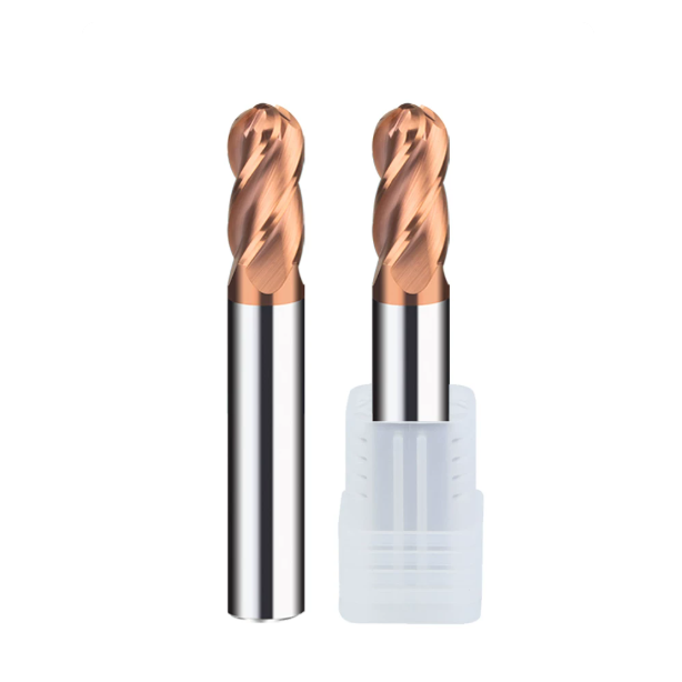
Peel Milling for Finishing Hardened Sidewalls and Deep Slots: Achieving Ra 0.2 Surface Roughness Prior to Polishing
Finishing hardened cavity walls with traditional shallow Z-level waterlines creates massive shop bottlenecks. Running hundreds of shallow passes leaves fine witness scallops that force bench hands to spend 15 to 20 hours hand polishing. Hand work risks washing out sharp parting lines and holding tolerances. Peel milling solves this by swapping shallow steps for deep axial engagement and tiny radial steps, peeling steel like a precision lathe.
We run this setup at tool shows and production facilities worldwide. When your setup is rigid and holder runout stays under 3 microns, a precision ballnose endmill running peel paths consistently hits finishes between Ra 0.2 and Ra 0.4 µm directly off the spindle. That cuts bench polishing time by up to 70% and eliminates surface distortion, ensuring smooth, drag-free plastic part ejection.
Practical Application of Shallow Radial Depth (ae ≤ 2% D) and Large Axial Depth (ap): Distributing Tool Tip Wear via the Ball-Nose Arc Cutting Edge
Many programmers hesitate to bury a cutter deep along a hardened wall, fearing cutting loads will break the tool. The physics actually work in your favor: taking light axial cuts focuses heat and load right at the ball tip, wearing out the cutter nose quickly. Peel milling trades cut width for cut depth, maximizing axial depth while capping radial step-over at 1% to 2% of tool diameter.
Testing on HRC54 grade 420 stainless mold steel showed this spreads the cut along an extended peripheral contact patch. Thin chips drop side-thrust forces and spread cutting heat across the full flute length rather than cooking the nose. Pairing this strategy with a dedicated ballnose endmill for hardened steel doubles or triples tool life compared to step-down waterline milling.
Eliminating Witness Marks: Climb/Conventional Milling and Entry/Exit Techniques for North American Medical Device Clients
Last year we helped a Boston medical tooling vendor clean up surface finishes on HRC58 powder-metal mold inserts. The customer kept fighting vertical witness lines and micro-steps on pocket walls, with CMM scans showing waviness exceeding 5 microns. The shop tried adjusting feeds, speeds, and tool brands, but the surface marks remained.
The real breakthrough came from reprogramming the lead-in and lead-out toolpaths. We ditched all straight-line plunges and exits in favor of sweeping tangential arcs paired with overlapping helical roll-outs. We also forced pure climb milling throughout the cycle, preventing the sudden deflection changes common in conventional cuts. Running a rigid carbide ballnose endmill with this path cleared the steps, delivering a clean finish under optical inspection.
Practical Application of Lead Angle Compensation in High-Speed 5-Axis Peel Milling with Carbide Ball-Nose Endmills
If you run a 5-axis machine, never keep the tool axis perpendicular to the cut surface on hardened steel. A 3-axis machine forces you to cut with the center tip, where surface footage drops to dead zero. A 5-axis machine allows you to tilt the tool, steering the contact point away from that center dead zone. Driving the ball center into hard steel creates micro-welding, smeared finishes, and chatter.
When peel milling steep walls on HRC62 dies, we program a 15° to 20° lead angle with a 5° tilt along the wall contour. This keeps cutting contact on the sweet spot of the carbide ballnose endmill, where peripheral speed is highest and flute geometry shears cleanly. Bypassing the zero-speed tip kills chatter, keeps spindle load steady, and produces an out-of-the-machine mirror finish.

CAM Path Settings and Machine Spindle Rigidity: A Typical Programming-Induced Failure We Encountered in a Customer’s Workshop
When shops call us about broken tools or bad chatter, operators usually blame inconsistent tool batches or hard spots in the steel. On hardened steel, high shear stress magnifies every flaw in the machining setup. Tiny toolpath spikes or dynamic runout trigger destructive high-frequency resonance at the cut zone. Cutting forces then blow past the carbide’s yield point in milliseconds.
Our first diagnostic step is never swapping the cutter; we pull the spindle load logs and inspect the posted G-code. A huge gap often exists between theoretical CAM drive points and real-world servo acceleration limits. Running a precision carbide ballnose endmill across tight 3D contours requires smooth servo motion. Abrupt vector changes and low machine rigidity remain the primary silent killers of cutting edges.
Feed Scheduling (Adaptive Feed Optimization): A Solution for Sudden Spikes in Cutting Load on Sloped Surfaces
While optimizing programs for an Italian automotive injection mold maker, we caught a major flaw on cavity draft walls. The programmer ran a single fixed feed rate across the entire 3D surface. As the tool transitioned from a flat pocket floor to a steep 60° wall, the contact patch and chip volume doubled instantly. Spindle load spiked hard, the cut squealed, and the edge chipped from severe over-engagement.
We fixed this by enabling adaptive feed scheduling inside their post-processor. The routine automatically drops the programmed feed rate by 25% to 35% before entering steep walls, ramping back up smoothly once the load stabilizes. This keeps cutting forces steady on your ballnose endmill for hardened steel across 3D surfaces. It prevents tool deflection, eliminates gouging, and stops sudden tip fractures.
Machine Tool Acceleration/Deceleration and Dynamic Balance Limits: How Tool Holder Runout (> 0.003mm) Can Instantly Destroy a Tool During Peel Milling
In hard peel milling, total indicated runout (TIR) allows zero compromise. When your radial step-over ($a_e$) is only 0.05mm to 0.15mm, runout above 0.003mm forces one flute to take almost all the load. This uneven mechanical shock causes micro-chipping on the loaded tooth within minutes. Once that single tooth fails, catastrophic breakdown of the entire tool follows immediately.
At a Swiss watch mold shop, operators fought erratic tool life using standard ER spring collet chucks. We measured tool-tip runout on the spindle with a test indicator; it clocked at a terrible 0.008mm. At 20,000 RPM, tools broke in under ten minutes. We mandated a switch to high-rigidity hydraulic or shrink-fit holders balanced to G2.5 at 25,000 RPM. Running an 8mm ballnose endmill in that rigid setup delivered whisper-quiet cutting and an Ra 0.2 µm mirror finish.
Setting Trochoidal Arc Radii for Deep Cavity Corner Clearing: Why the Programmed Corner Radius Must Never Equal the Tool Radius
The most common mistake we see in deep cavity rest-milling is matching the programmed corner radius to the tool radius. If you use an R4 ballnose to clear an R4 inside corner, tool engagement jumps from 15° to a full 90° or 180° wrap at the vertex. That instantaneous load spike pinches the tool against the stock, snapping the neck in a split second.
We train programming teams on one strict geometry rule: always keep the programmed inside corner radius at least 10% to 20% larger than your ballnose endmill radius. If print tolerances require an exact tight corner, program trochoidal looping paths to peel away stock layer by layer. Giving the tool room to breathe eliminates full-slot jamming and lets the machine spindle glide through tight corners smoothly.

A Breakdown of Tool Manufacturing: The Quality Baseline for a Competent Ballnose Endmill Manufacturer
Machinists often notice that identical CAM code yields totally different tool life when switching between different tool brands. When machining steels between HRC55 and HRC65, cutting tools have zero margin for error. A reliable ballnose endmill manufacturer does far more than grind flute dimensions to a print; they maintain strict control loops covering tungsten carbide grain structures, profile runout, and coating adhesion.
Having spent decades on grinding floors and supporting mold shops globally, we know shops fear unexpected chipping and batch-to-batch inconsistency most. If one tool cuts for four hours while the next shatters in forty minutes, the root cause is almost always tool manufacturing quality. Microscopic substrate flaws get amplified under high-frequency cutting impacts, ruining your dialed-in machining parameters.
Sub-Micron Carbide Substrates: Why Do Standard Carbide Grades Fail to Withstand the High-Frequency Impact of Hardened Steel?
When engineering tooling for hard die steels, we tested dozens of tungsten carbide grades with different cobalt binder ratios. Many machinists assume harder substrate grades are always better for hard milling. In reality, harder standard grades are far too brittle. High-speed trochoidal passes above 10,000 RPM produce thousands of mechanical shocks every second; coarse carbide grains quickly propagate into broken tool shanks.
To achieve maximum wear resistance alongside high impact toughness, we build our carbide ballnose endmill lines using ultra-fine sub-micron rods (0.2 to 0.5 µm grain size) with 8% to 10% cobalt. This dense microstructure locks grain boundaries tight, dampening sudden cutting force spikes. If you experience frequent tool breakage on tough cold-work steels, check your substrate specs; upgrading to ultra-fine grain carbide with high transverse rupture strength often solves the problem.
Nano-composite coating (nACo / AlCrN) adhesion testing: Ensuring edge sphericity and coating bond integrity before shipment
Instant cutting zone temperatures routinely exceed 800°C during hard peel milling, making the PVD coating your primary heat shield. When checking coating quality, we inspect oxidation resistance and interface bond adhesion rather than surface shine. Nanocomposite nACo or high-aluminum AlCrN coatings offer extreme hot hardness, but poor substrate preparation causes rapid flaking under heavy shear loads, burning the cutting edge within seconds.
Beyond coating bond strength, true sphericity across the cutting ball profile is non-negotiable. In our grinding facility, every high-precision ballnose endmill for hardened steel faces white-light interferometry and optical verification before shipping. We hold ball profile accuracy strictly within $\pm 0.003\text{ mm}$. If you struggle to clear witness marks on cavity sidewalls, check the tool’s ground sphericity; surface finishes stall above Ra 0.2 µm if the ball radius is ground out of round.
Practical Feedback Mechanisms for Troubleshooting Abnormal Tool Breakage (As a Veteran Ball-Nose End Mill Manufacturer)
Supporting precision mold shops across North America and Europe taught us that a cutting tool supplier must serve as an extension of your programming room. When a customer reports premature edge failure or unexpected chipping, we never guess based on a cell phone picture. We review the full dataset: spindle specs, measured holder runout, raw CAM files, and perform metallographic microscope analysis on the returned worn cutters.
True toolpath optimization is a collaborative engineering process between the shop floor and the tool grinder. If you face tough challenges like clearing deep ribs above HRC60, stabilizing thin-wall peel cuts, or solving strange chipping, send us your cutting parameters, workpiece drawings, and steel specs. Working together as your dedicated ballnose endmill manufacturer, we can dissect the real cutting forces and lock in a reliable process that protects your margins.