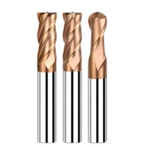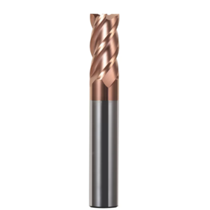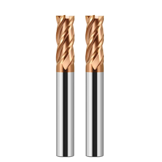
Last month, a precision injection mold partner in Stuttgart sent us shop-floor footage. A 5-axis center was finishing a deep headlight mold cavity. The setup paired pre-hardened NAK80 (HRC 38) with a hardened H13 insert (HRC 52). After the first pass, a dial indicator revealed 0.035mm of tool deflection at the bottom wall. On the second pass, the tool engaged the bottom corner, gave a sharp snap, and chipped immediately.
Their shop supervisor asked us frankly: “Is there no universal flat end mill for both, or are our parameters totally off?” In fifteen years of tool grinding and technical support, we have seen this issue repeatedly. Mold shops rush jobs by pushing one batch of 4 flute carbide end mill cutters across different material hardness levels. But pre-hardened mold steel and heat-treated die steel behave like entirely different beasts.
P20 and NAK80 are soft yet gummy, easily generating built-up edges that leave wavy sidewalls. Hardened H13 spikes thermal loads instantly. Standard coatings burn off under dry cuts, and a long-reach 6mm end mill cutter will deflect or snap under minor cutting resistance. The fault rarely lies with machine rigidity. Rather, the chosen endmill lacks the grain structure, edge prep, and helix geometry for the task.
As carbide end mill manufacturers working directly with mold shops, we know the cost of scrapped inserts. We have helped hundreds of facilities resolve persistent chatter and chipping issues. In your daily shop operations, do you find yourself constantly balancing wall finish against tool life? Or must you drop feed rates to unprofitable levels just to keep your cutters intact?

From Pre-Hardened to Quenched Steels: Key Machining Challenges and Flat-Bottom End Mill Selection Criteria for P20, NAK80, and H13
While providing on-site technical support, we often see operators take risky shortcuts. They run a standard flat end mill in a pre-hardened cavity, change the program, and dive into a quenched insert. The outcome is predictable: either the sidewall develops heavy chatter marks, or the corner radius fractures instantly. Spindle rigidity is rarely the root cause. Cutting physics and heat transfer change fundamentally between these steels, so one edge geometry cannot handle both.
To stop tool deflection and edge chipping, tooling selection must go beyond “anything that cuts.” Plastic mold steels and die-casting steels feature very different core microstructures. We evaluate plastic deformation resistance and thermal conductivity before picking carbide grain sizes. A solid flat end mill balances core hardness, substrate toughness, and flute capacity. You must weigh sharp shear action against core rigidity under radial cutting forces.
Adhesion and Work Hardening in P20 and NAK80: Why General-Purpose Flat End Mills Often Fail Prematurely During Corner Cleaning
When machining P20 (HRC 30–34) or NAK80 (HRC 38–41), the main challenge is material adhesion, not abrasive wear. Both alloys flow under heavy cutting pressures. Extreme shear heat cold-welds micro-particles onto the rake face, forming a built-up edge. This distortion alters cutting geometry and gouges vertical walls. Consequently, achieving a clean finish during light cleanup passes becomes very difficult.
Many shops still use standard, general-purpose flat end mill cutters for tight cornering. However, these tools usually have conservative rake angles and lack mirror-polished flutes. As the cutter reaches internal corners, the engagement angle spikes. Gummy chips get recut inside tight flutes, tearing the surface and chipping the outer edges. For these grades, open flutes and lower friction beat absolute edge strength every time.
High-Temperature Cutting Loads on Quenched H13 (HRC 50–54): The Essential Requirement for Specialized End Mills for Hardened Steel
Machining quenched H13 (HRC 50–54) introduces totally different physical challenges. After heat treatment, tensile strength jumps and cutting forces rise exponentially. Thermal energy cannot escape quickly through the chips, so high heat transfers directly into the cutting edge. Flood coolant causes severe thermal cycling, creating microscopic stress fractures in the carbide matrix that lead directly to tool failure.
For these reasons, we require operators to switch to dedicated end mills for hardened steel. These tools do not rely on blunt impact. Instead, they feature defined edge honing with negative rakes and high-aluminum PVD coatings rated past 1,000°C. Running dry with high-pressure air blast at elevated surface speeds plasticizes the shear zone cleanly. Standard tooling running here suffers severe flank wear before finishing even two passes.
Real-World Testing by Tool Manufacturers: The Decisive Impact of Substrate Toughness and Micron-Level Tolerances on the Service Life of 6mm End Mills in Long-Reach Applications
Small-diameter tools remain the most delicate choice for deep cavities and narrow ribs. Our bench grinding tests confirm that once a 6mm end mill cutter exceeds a 4:1 or 5:1 length-to-diameter ratio, deflection scales with the cube of the overhang. If the carbide rod lacks sufficient transverse rupture strength, the cutter chatters under transient corner loads. From there, sudden shank failure quickly follows.
Procurement teams often focus solely on unit price, but manufacturing precision determines actual floor performance. If a 6mm tool carries more than 0.003mm total runout (TIR) in a hydraulic or shrink chuck, tooth loads become asymmetrical. One flute absorbs excessive impact, cutting overall tool life in half. In deep cavity work, substrate toughness and concentricity consistently protect your parts better than extreme hardness alone.
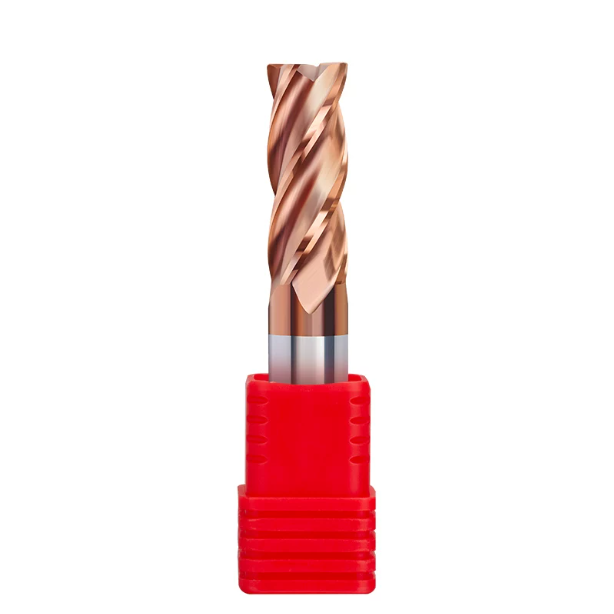
Solving Wall Smearing and Tool-Pass Marks on P20 and NAK80: Configuring 4-Flute Carbide End Mills and Cutting Strategies
When finishing precision injection mold cavities, dull drag marks and visible step-overs along the sidewalls ruin surface quality. On the shop floor, we find this usually happens when operators treat finishing like roughing. Pre-hardened steels undergo plastic flow under intense shearing pressure. When chips get smeared against the wall instead of cleanly sheared, surface integrity drops immediately.
To stop these sidewall flaws, we balance core thickness, flute curvature, and radial engagement. A reliable process maintains chip thickness strictly above the critical rubbing threshold rather than forcing heavy cuts. Pairing a dedicated 4 flute carbide end mill with climb milling and constant surface footage holds vertical walls square. It also cuts manual polishing time significantly.
Why the 4-Flute Carbide End Mill is the Baseline Solution for Vibration Control and Ra 0.4 Surface Finish on NAK80 Sidewalls
Machinists often ask why we favor a four-flute tool over a two-flute tool for sticky NAK80. While two flutes provide larger chip pockets, precipitation-hardened NAK80 (around HRC 40) lacks natural dampening properties. As overhang increases during vertical wall cleanup, two-flute cutters suffer severe regenerative chatter. This leaves dense vibration ripples across the cavity walls.
Choosing a rigid 4 flute carbide end mill provides the torsional stiffness needed for light finishing passes. Continuous tool engagement smooths out radial cutting forces and prevents the cutter from deflecting under light step-overs (Ae 0.05–0.1mm). With proper primary relief, the flutes shear the deformed layer cleanly. This reliably maintains an Ra 0.4 finish before polishing.
Cutting Oil or High-Pressure Air Blast? Chip Evacuation Parameters to Prevent Built-Up Edge (BUE) on Flat End Mills in Real-World Machining
Coolant choices for sticky steels often split operators between flood coolant and dry cutting. In our experience, water-based coolants often vaporize before penetrating the cut zone during high-speed passes. This creates rapid thermal cycles that accelerate chip welding on the rake face. Once a built-up edge forms, the flat end mill dulls rapidly and scratches the workpiece sidewalls.
For enclosed pockets, high-pressure air combined with Minimum Quantity Lubrication (MQL) works best. Aim a dry air blast of at least 0.6 MPa directly at the tool exit point to evacuate chips immediately. Pair this with a crisp feed rate of 0.03–0.05 mm per tooth to stay ahead of the work-hardened layer. Evacuating hot chips prevents recutting and keeps the cutting edges sharp.
Avoiding Chipping Caused by Reckless Plunging: Practical Settings for Helical Entry in Enclosed Mold Cavities
The most critical moment in cavity milling is opening a pocket from solid stock. Some operators plunge straight down along the Z-axis or ramp down too aggressively. Because center cutting velocity drops near zero at the center of the endmill, chips cannot escape easily. This forces the bottom teeth to grind against trapped chips, causing overload alarms and chipped corners.
We always program a smooth helical entry path in closed areas. On gummy steels like P20 and NAK80, keep the ramp angle between 1.5° and 2.5°. Set the helical orbit diameter between 1.3 and 1.5 times the cutter diameter. This allows the bottom and outer edges to share the load, curling thin chips that evacuate upward smoothly without jamming.
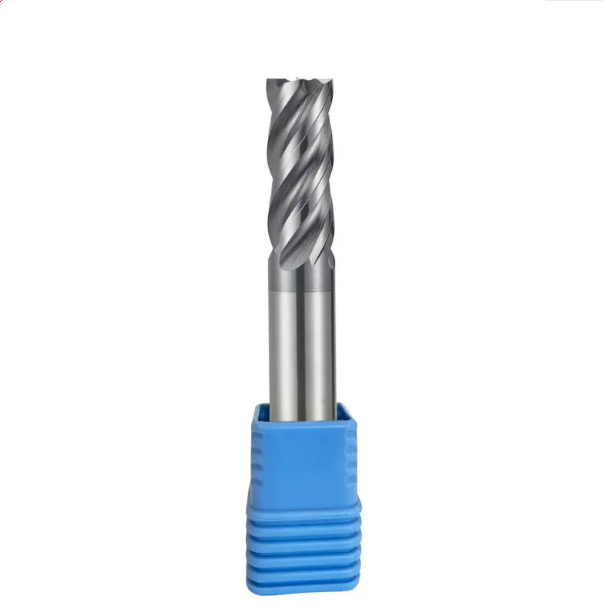
Mastering Hardened H13 (HRC50+): Practical Experience with HRC65 Carbide Flat End Mills for Direct Hard Milling
Direct hard-milling of heat-treated H13 inserts (HRC 50–54) replaces slow EDM work and eliminates surface recast layers. However, hard milling demands strict tool stability and rigid machine dynamics. Many shops attempt to cut hardened materials using standard speeds and feeds. The cutter corners wear out within thirty minutes, leaving heavy gouge marks on expensive dies.
Stable hard milling requires steady plastic shearing rather than aggressive, hammering cuts. Through extensive testing, we found chips must shear away uniformly without sudden force spikes. For high-temperature, heavy-load milling, run a carbide flat end mill hrc65 designed for extreme hardness. Combine high spindle speeds with light radial depths of cut to maintain strict dimensional accuracy.
Avoid Using General-Purpose End Mills on Hardened Molds: Practical Principles for Corner Clearing with HRC65 Carbide Flat End Mills to Prevent Chipping
Clearing hardened internal corners causes frequent tool breakage. Operators often run tools straight into 90-degree internal transitions. This spikes tool engagement from a light arc up to 180 degrees in a fraction of a second. The resulting force surge shatters conventional carbide edges. Instead of normal flank wear, the entire corner edge shears off instantly.
When clearing corner stock with a carbide flat end mill hrc65, you must avoid sharp 90-degree transitions. Always program trochoidal paths or corner deceleration loops in your CAM software. Keep radial step-over between 2% and 5% of tool diameter with shallow axial passes. Rolling smoothly into corners absorbs peak shocks and prevents microscopic chipping at the cutter tip.
Tailoring Micro-Negative Rake Angles and Edge Honing for High-Hardness Steel End Mills: Our Manufacturing Strategy to Prevent Micro-Chipping
Tool geometry for hardened steel requires a different approach than soft alloys. Standard tools use sharp positive rakes to reduce cutting forces. However, razor-sharp edges chip like glass against hard carbides in quenched steel. When cutting heat-treated H13, the microscopic cutting edge needs strong structural backing to transfer cutting pressure into the solid tool body.
We grind these tools with a micro-negative rake of -5° to -8° and apply a 5–10 micron edge hone on 5-axis grinders. While this rounding slightly raises thrust forces, it removes microscopic grinding wheel burrs. Paired with an ultra-hard nano-composite coating (up to 3600 HV), this fortified geometry compresses and shears hard materials without micro-flaking along the cutting edge.
Switching from Emulsion Coolant to Cold Air: Temperature Control to Prevent Thermal Shock Micro-cracks When Machining H13 Steel
Operators often blast flood coolant on glowing tools during H13 machining, thinking it protects the edge. But in high-speed cuts, tooth temperatures hit 800°C in the cut and cool down rapidly upon exit. Under an electron microscope, failed tools show dense comb cracks running perpendicular to the edge. This micro-cracking is caused directly by thermal shock fatigue.
To stop thermal failure, run specialized end mills for hardened steel with high-pressure cold air or dry gas blasts. Cold air does not need to chill the cutter down to room temperature. Instead, it stabilizes cutting zone temperatures and blows hot chips away instantly. Avoiding thermal cycling and chip recutting is the most dependable way to double your tool life.
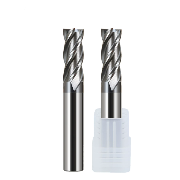
Machining Deep Cavities and Micro-Features in Molds: Managing 6mm End Mill Deflection on the Shop Floor
Machining automotive lighting dies or electronic connector housings forces you into deep, narrow pockets. Large tools cannot clear these ribs, so operators must reach for slender, extended-reach cutters. We often see CMM reports revealing tapered sidewalls or bulging profiles despite accurate CNC readouts. The toolpath was accurate, but physical part dimensions drifted outside acceptable limits.
This deviation stems from elastic bending under continuous lateral cutting pressure. As cantilever length increases, radial stiffness plummets drastically. For a common 6mm end mill cutter, simply dialing back spindle speed will not stop chatter. Without strict control over radial engagement, tool deflection, and chip load dynamics, you will inevitably scrap tight-tolerance mold cavities.
Why 6mm End Mills Are Prone to Deflection During Vertical Wall Finishing: Feed Compensation Techniques for Overhang Ratios Exceeding 3D
When a 6mm end mill cutter runs at length-to-diameter ratios past 3:1 or 5:1, cutting resistance magnifies along the extended shank. Cantilever deflection scales with the cube of overhang length, meaning an overhang change from 18mm to 30mm multiplies bending sensitivity. A light 0.05mm finishing allowance might only cut 0.02mm under pressure, leaving residual stock that creates noticeable dimensional taper.
Do not rely on spring passes and hope the wall straightens out. We program segmented feed reductions of 15% to 20% in high-resistance lower pocket zones to drop peak thrust. Combine this with CAM-driven bottom-up climb milling passes. Freshly cut lower floors support the cutter against elastic rebound, stabilizing deflection and maintaining perpendicular sidewalls.
Practical Application of High-Efficiency Milling (HEM) in Mold Roughing: Using Flat End Mills with Shallow Radial and Deep Axial Cuts to Relieve Chip Evacuation Pressure
Traditional pocket roughing uses heavy step-overs with shallow axial depths. In hardened tool steels, this brute-force approach concentrates excessive heat right at the corner tip. Chips cannot escape narrow slots, welding into the flutes and chipping the cutter corners. That high-pitched squeal heard across the floor confirms the tool is choking on asymmetrical loads.
We transition shops to High-Efficiency Milling (HEM) paths instead. Run a premium flat end mill down to 1.5x or 2x tool diameter in axial depth, paired with a light 5% to 10% radial step-over. This spreads friction along the full flute length. Centrifugal force and high-pressure air blast eject thin, uniform chips cleanly, doubling metal removal rates while eliminating tool binding.
Dynamic Balance and Clamping Runout: Why Controlling TIR to Within 0.003mm Can Double the Tool Life of a 6mm Cutter
Walking through many mold shops, you still see battered ER collet chucks run past their service life. Machinists assume that low cutting loads on a 6mm end mill cutter make 0.01mm runout acceptable. In reality, 0.01mm Total Indicated Runout (TIR) forces one flute to take almost all the impact while other teeth slip.
This cyclic imbalance triggers micro-spalling on the overloaded cutting tooth, leading to rapid tool breakage. We mandate mounting small tools inside precision hydraulic or heat-shrink tool holders. Use a dial test indicator to check runout 20mm below the holder nose, holding TIR under 0.003mm. Balancing chip load evenly across all flutes consistently doubles tool life on production runs.
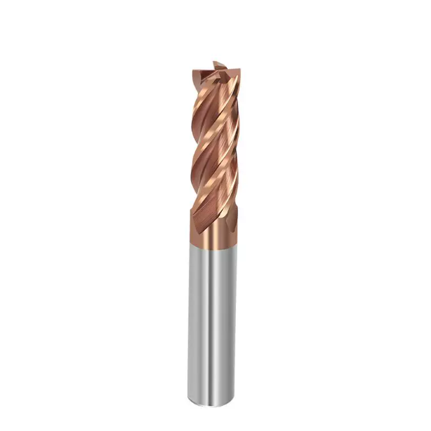
How Mold Manufacturers Can Avoid Pitfalls: Advice from Carbide End Mill Manufacturers on Verifying Supplier Qualifications
Visiting toolrooms across North America and Europe, we frequently spot a clear purchasing disconnect. Purchasing managers buy solely on price, assuming all solid carbide tools perform the same. Meanwhile, machinists struggle with erratic batch consistency, watching one cutter last eight hours while the next chips out in thirty minutes. From our grinding lines, we know raw materials and five-axis geometry define performance.
If your floor battles premature chipping in H13 or uneven wall finishes in P20, check your tool supply chain. Reliable carbide end mill manufacturers deliver proven consistency, not just packaged tools. Strict dimensional sorting, sub-micron grain standards, and automated edge honing guarantee repeatable tool life. That internal quality control allows operators to push aggressive feeds with complete confidence.
Virgin Carbide Stock vs. 5-Axis Grinding Precision: The Real Gap in Manufacturing Consistency
Chasing low purchase prices causes buyers to overlook carbide substrate quality. Budget cutters frequently use recycled carbide grades containing uneven grain distributions and micro-porosity. These flaws fracture easily against hard carbide clusters in mold steels. As reputable carbide end mill manufacturers, we source ultra-fine virgin tungsten carbide rods (0.2–0.4 micron) to supply the core toughness needed for negative rakes and PVD coatings.
Grinding machine stability and wheel dressing intervals also dictate final batch quality. Inspect cutters under high magnification to check micro-honing consistency and flute rake transitions. World-class grinding centers hold edge-honing radiuses within a two-micron tolerance across entire production runs. Inconsistent grinding creates uneven flute heights, causing immediate chatter and drastic tool life fluctuations on your machines.
Stop Paying for Unnecessary Premiums: Material Matching and Cost-Reduction Strategies for Mold Shops’ Monthly Bulk End Mill Procurement
Over-specifying cutters is another costly trap. Shops often buy expensive aerospace-grade tooling to cut standard pre-hardened cavities around HRC 30. That high-heat coating and negative rake angle are wasted on softer steels, often worsening built-up edge and workpiece smearing. Real savings come from matching specific cavity physics to targeted cutter geometries rather than hunting cheap list prices.
Review your monthly endmill orders and separate tools by manufacturing stage. Use polished, vibration-dampening geometries for high-volume cavity clearing, and reserve balanced, low-runout tools for long-reach finishing. Save dedicated heat-resistant coatings and negative edge hones exclusively for hardened inserts. If you face tough cavity prints or tight deflection tolerances, contact our engineering team to review your drawings and setup details.