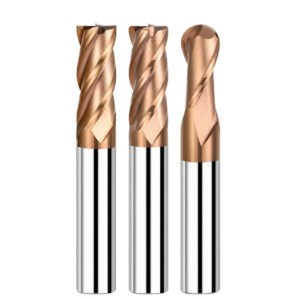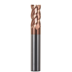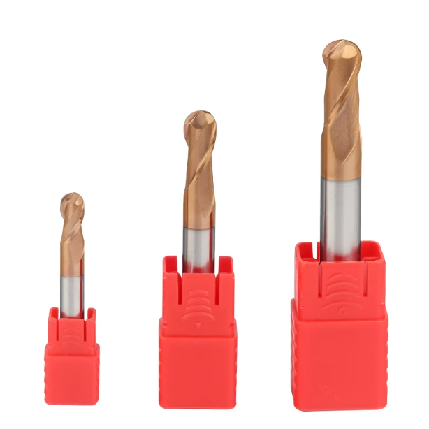
Last month, a long-standing client—a valve and fluid fittings manufacturer in Stuttgart, Germany—shipped two severely damaged tools back to our grinding lab. They were 5-axis finish-milling complex internal flow channels on high-pressure valve cores, running mixed batches of AISI 304 and 316. The setup used identical toolpaths, speeds, feeds, and the exact same premium carbide ball end mill.
The results were polar opposites. On the 304 batch, the tip suffered severe micro-chipping after barely completing two parts. On the 316 batch, chipping was not the issue; instead, severe workpiece adhesion caused a massive built-up edge (BUE). This tore the finished surface to worse than Ra 3.2, grinding production to a halt.
This type of tooling failure happens frequently in production facilities. Many programmers simply group 304 and 316 under the general banner of “austenitic stainless steel.” They load a generic end mill ball nose for stainless steel into the carousel and expect clean results. But anyone with real-world spindle time knows these two alloys demand distinct cutting dynamics.
The challenge with 304 centers on rapid work-hardening: any rubbing immediately spikes surface hardness, shattering the cutting edge. Conversely, 316 introduces high-temperature adhesion and poor thermal conductivity. Its 2% to 3% molybdenum (Mo) content makes chips dense and sticky, trapping extreme heat directly on the micro contact arc.
Selecting the right tool goes far beyond pulling standard lengths from a catalog. Deep cavity contouring often requires a stainless steel 2 flute ball nose end mill to provide the necessary gullet volume and prevent chip recutting. In tight corners, matching the right ball nose end mill sizes to your corner radii determines whether the tool shears cleanly or simply burns up.
When your spindle screams at 7,000 RPM and the cut floor shows scaly chatter marks, are you certain that the tool in your holder is matched to the metallurgy on your table?

The Real Differences in Machining Characteristics Between 304 and 316: The Truth About Tool Wear Observed on the Shop Floor
Whenever we troubleshoot 5-axis setups on-site, we verify the material callout on the print before checking spindle speeds. To a purchasing department, the difference between 304 and 316 may look like raw material pricing. At the high-speed shearing zone, however, each alloy destroys a cutting edge in a completely different way.
Lab analysis on returned cutting tools reveals a distinct pattern. Failures on 304 stem almost entirely from micro-chipping and mechanical impact fatigue. On 316, cutting edges are coated with welded material torn from the workpiece. Understanding these wear dynamics is critical before selecting an application-matched ball nose end mill for unattended production runs.
The Work-Hardening Trap of 304 Stainless: Why Standard Ball Nose End Mills Often Chip
The primary hurdle with 304 is its rapid work-hardening rate under compression. Operators frequently make the mistake of dropping step-overs and chip loads too low to chase surface finish. When feed-per-tooth falls below the edge hone radius, the tool stops shearing and begins burnishing the material under intense pressure.
This burnishing action creates a hardened surface layer far tougher than the base metal. Standard tools with insufficient substrate toughness quickly micro-chip against this cold-rolled skin. When running a carbide ball end mill on 304, maintaining a healthy minimum chip thickness avoids surface rubbing and protects the cutting edge from premature failure.
High Stickiness and Heat Accumulation in 316 Stainless: A Severe Test for Ball Nose End Mills
Switching to 316 shifts the primary wear mechanism from mechanical shock to thermal adhesion. Molybdenum increases plastic deformation resistance during chip formation, meaning heat does not evacuate with the chips. Instead, over 70% of that thermal load concentrates directly at the cutting zone.
This heat concentration triggers chemical affinity between the workpiece and the tool substrate, welding chips directly to the rake face. Machining this material requires a specialized end mill ball nose for stainless steel featuring polished flutes and high-temperature lubricity coatings. Pairing this geometry with high-pressure coolant breaks the vapor barrier, flushing chips out before welding occurs.

Substrate, Flute Count, and Geometry: Customization Logic for Carbide Ball End Mills for Two Types of Stainless Steel
Visiting shop engineers often ask us which coating provides the highest wear resistance. After grinding tools on 5-axis machines for over a decade, we know coating is merely the final touch. Substrate grain selection, core-to-diameter ratio, and micro-geometry dictate whether a tool lasts three minutes or three hours. Given the rapid strain hardening of 304 versus the thermal deformation of 316, one geometry cannot master both alloys.
When manufacturing custom carbide ball end mill solutions for 304, we use a sub-micron tungsten carbide rod with 10% cobalt to balance transverse rupture strength with edge toughness. For sticky, heat-retaining 316, we select an ultra-fine grain substrate paired with mirror-polished flutes. Without adequate substrate rigidity under heavy shearing forces, even the most advanced PVD coating delaminates prematurely.
2-Flute Chip Evacuation vs. 4-Flute Rigidity: Why We Recommend the 2-Flute Ball Nose End Mill for Deep Cavity Profiling
In deep cavities or tight corner profiling, machinists often reach for a 4-flute cutter to maximize core stiffness and feed rates. In enclosed austenitic stainless pockets, however, a 4-flute design frequently causes sudden failure. Stainless chips resist curling, and narrow flute valleys quickly choke. Trapped chips get recut, triggering spike cutting loads and immediate chatter.
This is why we advocate running a stainless steel 2 flute ball nose end mill in deep 3D cavities. The open flute geometry provides generous gullet space, evacuating hot chips instantly before they weld to the cutter gullet. You sacrifice a fraction of theoretical core rigidity and must meter the chip load, but the gain in process reliability prevents unexpected scrap parts.
Overcoming the “Zero SFM” Dead Zone at the Tool Tip: Practical Tests on Ball Nose Rake Angle Grinding and Runout Control
Contouring with any spherical cutter means confronting a physical reality: cutting speed drops to zero at the tool center axis. When stepping across shallow workpiece profiles, the center tip drags and smints material at 0 SFM. On work-hardening alloys like 304, this rubbing creates intense stress. Over half the failed tools inspected in our lab chipped first at the center chisel edge before tearing outward.
In standard 3-axis setups lacking tool tilting options, we solve this with specialized tool grinding and strict concentricity control. We grind an S-shaped split point or eccentric relief to deliver a positive shearing edge across the center. Furthermore, total radial runout must stay below 0.0001 inches (3 µm) to protect this end mill ball nose for stainless steel from unbalanced impact shock.
Practical Coating Selection: Comparing AlTiN vs. AlCrN Tool Life in 316 Curved Surface Machining
Coating performance in 316 stainless is about thermal insulation and anti-welding properties along the small contact arc. Conventional AlTiN performs reliably in general steels and 304, but it struggles with the thermal loads of molybdenum-rich 316. Cutting zone temperatures regularly exceed 800°C, causing aluminum migration, coating embrittlement, and rapid edge weldment.
In head-to-head cutting tests, AlCrN coatings consistently outlast titanium-based alternatives on 316. AlCrN develops a dense chromium-oxide barrier between 900°C and 1100°C, significantly reducing sliding friction against gummy stainless chips. Flooding this ball nose end mill with high-pressure internal coolant stops built-up edge (BUE) formation and protects critical 3D part geometry.
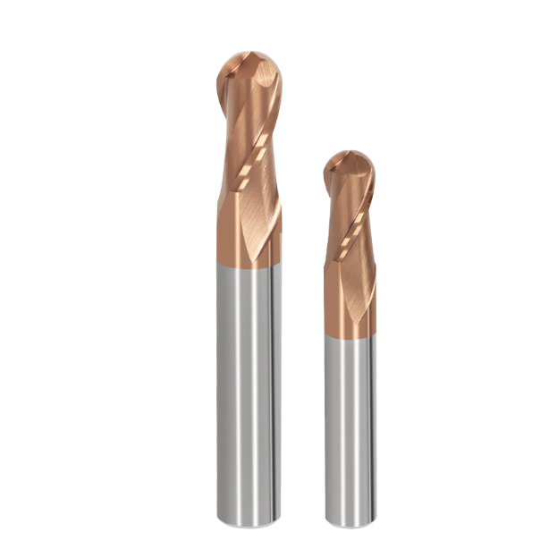
Specification Matching and Toolpath Optimization: Machining Strategies for Various Metric End Mill Sizes
We frequently diagnose shop-floor issues where parts show heavy gouging or incomplete internal corner cleanup. The root cause is rarely machine dynamic rigidity; rather, it stems from programming errors when transitioning between metric end mill sizes. Austenitic grades like 304 and 316 leave zero margin for unmanaged cutting loads or incorrect tool stepping.
Tool stepping must obey geometric fundamentals. Forcing a large cutter into tight internal radii spikes tool engagement angles and triggers harmonic deflection. Dialing in dimensional tolerances and mirror finishes requires combining stepped tool diameters with balanced semi-finishing allowances across the entire toolpath sequence.
Precision Corner Clearing and Surface Finish: Matching Ball-Nose End Mill Sizes with Corner Clearance Tolerances
In medical mold and turbine blade machining, programmers often struggle with persistent witness marks in internal corners. This occurs when the programmed ball nose end mill sizes directly match the blueprint fillet radius. The cutter enters full radial engagement, wrapping the entire cut arc, spiking cutting forces, and chipping the tip.
Our shop protocol keeps semi-finishing cutter radii roughly 20% smaller than the final pocket fillet. This leaves an even stock skin for the final cleanup pass. The finishing tool then shears a uniform, thin chip without tool deflection, completely eliminating transition lines and surface burnishing.
Feed Rate and Effective Cutting Diameter: Setting Cutting Parameters for Large vs. Micro-Diameter Metric End Mills
A frequent error among junior programmers is running constant spindle RPM across mismatched cutter diameters. Stepping down from a 16 mm tool to a 2 mm cutter without recalculating spindle speeds collapses surface footage (SFM). In shallow 3D contour cuts, the actual effective cutting diameter shrinks depending on the axial depth of cut (Ap).
We require shops to enable effective tool diameter compensation inside their CAM systems. Large metric end mill sizes handle higher chip loads due to superior thermal dissipation through the tool body. Micro cutters demand high spindle speeds, shallow axial steps, and precise feed control to prevent flex fatigue and sudden breakage.
Climb Milling or Trochoidal Milling? Practical CAM Strategies to Avoid Repeated Friction on Work-Hardened Surfaces
Toolpath trajectory dictates tool life in austenitic stainless. In poorly optimized CAM routines, cutters frequently wipe over previously cut surfaces during retracts or clearance passes. This rubbing against a work-hardened floor is far more damaging than active shearing, dulling the relief face and chipping micro-edges.
We mandate climb milling strategies that keep chip formation thick-to-thin and bar any non-cutting dwell motion. For enclosed slots or pocket entries, deploy continuous trochoidal arcs or smooth helical ramping. This stabilizes the engagement arc, dissipates heat into the chips, and shields the carbide ball end mill from hardened surfaces.

Shop-Floor Troubleshooting Checklist: Common Failures and Countermeasures for Ball Nose End Mills in Stainless Steel Contour Milling
Few occurrences on the shop floor are more frustrating than an unexpected machine alarm during a finishing pass. Unclamping the holder to find deep gouges or white, torn scuff marks across a sculpted profile can instantly derail production. These cutting anomalies signal an active imbalance between machine tool rigidity, coolant delivery, and micro-edge integrity.
We always pack a portable 40x optical microscope when troubleshooting at tier-one contract facilities. Inspecting the wear band immediately reveals whether you are battling impact spalling on work-hardened 304 or thermal adhesion on 316. Accurately diagnosing these failure modes is the fastest path to stabilizing tool life on any production ball nose end mill.
Spalling and Micro-chipping at the Ball Nose Tip: Our Troubleshooting Method for Spindle Vibration and Edge Honing
Notched, jagged micro-fractures along the tip arc within the first thirty minutes point directly to harmonic chatter or excessive runout. Our first troubleshooting step is mounting a 0.0001-inch test indicator directly to the spindle taper and collet nose. If dynamic runout exceeds 0.005 mm, one flute absorbs the brunt of the impact load, causing rapid fatigue failure.
When spindle mechanics and holder balance check out, we evaluate the micro-honing on the cutting edge. Machining austenitic stainless steel demands a controlled edge preparation rather than a razor-sharp profile. We prep our premium carbide ball end mill tools with a uniform 0.010 mm to 0.015 mm micro-hone, building a stable shear zone that absorbs continuous mechanical shock.
Addressing Built-Up Edge (BUE) and Tool-Pass Marks: Solutions via High-Pressure Coolant and Feed Compensation
Heavy witness steps and torn, scaly patches on contoured surfaces confirm that built-up edge (BUE) has hijacked the cut. In gummy 316, extreme shear heat pressure-welds micro-chips directly onto the rake face, artificially shifting the cutting radius. Flooding coolant over the holder does little good, as the resulting vapor barrier starves the cutting interface.
We resolve this by aiming internal coolant nozzles exceeding 20 bar directly at the shear zone. The fluid momentum blasts through the vapor barrier and clears stubborn chips out of the end mill ball nose for stainless steel. Programmers should also apply dynamic feed compensation in CAM to prevent chip load spikes as engagement wraps deeper into corners.

Factory Procurement and Mass Production Assessment: Controlling Batch Consistency for Wholesale Ball Nose End Mills
Moving from parameter optimization to production realities shifts the focus to one core metric: lot-to-lot consistency. Many machine shops achieve flawless initial test cuts, only to watch scrap rates climb as production scales into the thousands. This failure rarely stems from CNC drift; it is almost always caused by wide manufacturing tolerances between tool batches.
When managing volume production, single-tool performance matters far less than predictable tool wear curves across an entire shipment. Our quality standards for wholesale ball nose end mill orders enforce strict limits on flute runout, coating thickness, and carbide grain consistency. Without rigid batch quality control, fine-tuned CAM routines and dynamic tool offsets fail to keep part dimensions within tolerance.
Cost-per-Part Analysis: The Critical Role of TIR Tolerance in Wholesale Ball Nose End Mill Procurement
Calculating cutting-tool costs solely from invoice prices creates hidden losses on the production floor. In high-speed 3D milling, poor Total Indicated Runout (TIR) represents the largest hidden expense across a production run. When sourcing a wholesale ball nose end mill with runout jumping from 3 to 8 microns, one flute carries up to 70% of the mechanical load.
This dynamic runout accelerates tip wear and forces frequent machine stoppages for tool offsets and inserts. If you are calculating the actual cost-per-part on 304 or 316 stainless runs, evaluate the standard deviation of tool life and resulting scrap rates. High-precision tooling seated in shrink-fit holders stabilizes the wear curve, unlocking reliable, lights-out machining cycles.
Customizing Non-Standard Overhangs and Neck Lengths: Technical Acceptance Standards for Bulk Procurement of Ball Nose End Mills by Western Contract Manufacturers
Deep mold pockets, impellers, and complex fluid ports routinely expose the limits of standard catalog overhangs. Short tooling causes holder collisions, while excessive reach reduces tool rigidity and triggers chatter. When supporting contract manufacturers with specialized ball nose end mill sizes, we tailor neck clearance lengths and transition taper angles to the exact part geometry.
If you are fighting chatter marks or tool deflection in tight corner transitions, examine the physical clearance between your cavity walls and current cutter necks. Feel free to reach out to review prints, material lots, and spindle taper configurations together. We can collaborate directly with your team to establish ideal neck reliefs and edge hones suited to your cycle times.