
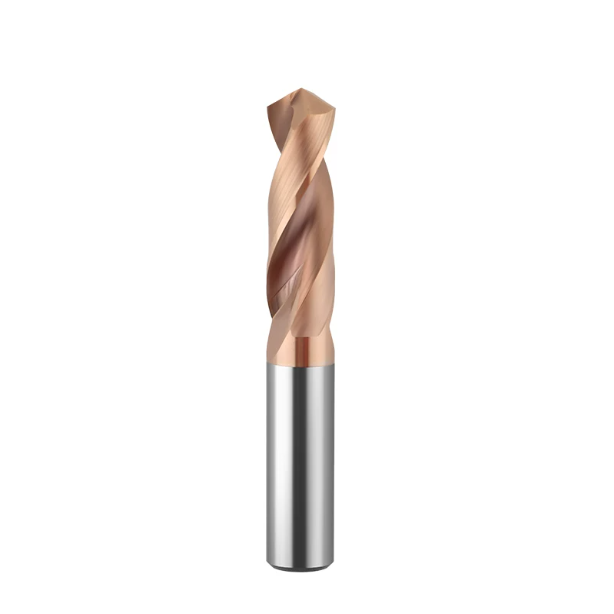
Last month, while troubleshooting on-site at an Ohio machine shop running hydraulic valve blocks, the shop supervisor pointed to a broken tool in the scrap bin. “We bought the most expensive cobalt tools on the market, and the print only calls for 4140 pre-hardened steel,” he said. “Why did the cutting edge burn out and chip before hitting thirty holes?”
We have seen this exact problem play out for over sixteen years across cutting tool manufacturing and CNC machine shops. Many machinists searching for the best drill bits for metal assume that a premium price tag guarantees success across all alloys. In reality, matching tool substrate and geometry to machine conditions matters far more than brand reputation.
Every metal—from gummy aluminum to hardened tool steels and nickel superalloys—places unique physical demands on the cutting edge. Factors like substrate grain size, cobalt binder content, flute geometry, and PVD coatings dictate performance. A reliable metal drill bit succeeds only when its micro-grain structure and edge prep match your cutting speeds, feed rates, and coolant pressure.
If your tool geometry conflicts with your material, tweaking speeds and feeds on the control will not rescue your cost per hole. As machinists who spend our days between tool grinders and CNC spindles, are you dealing with erratic tool life or premature micro-chipping on difficult alloys?
Why Is There No “One-Size-Fits-All” Metal Drill Bit?
Many shop owners want a single universal tool that can drill structural mild steel in the morning and hardened mold blocks in the afternoon. After visiting hundreds of machine shops across North America and Europe, we know that an all-purpose metal drill bit simply does not exist. Metals vary drastically in shear strength, thermal conductivity, and work-hardening rates.
Attempting to run a single drill grade across multiple material classes causes severe shop-floor headaches. Soft alloys quickly pack the flutes and weld to the margins, while high-strength alloys chip the cutting lips. Tool selection is always a balance between impact toughness and abrasive wear resistance, combined with your machine’s spindle rigidity.
From Low-Carbon Steel to High-Hardness Mold Steel: Determining Substrate Toughness and Hardness
When drilling soft, ductile steels like AISI 1018, long stringy chips tend to wrap around the tool body and weld to the cutting edge. To combat built-up edge (BUE), we specify a tougher substrate with a positive rake angle and mirror-polished flutes. This geometry uses sharp shearing action to curl and eject chips smoothly before they gall inside the hole.
When switching to pre-hardened 4340 or hot-work die steel over HRC 48, friction generates cutting zone temperatures that quickly destroy standard tool substrates. For these alloys, we switch to an ultra-fine submicron grade with low cobalt binder and reinforced negative land edge honing. Every step up in workpiece hardness requires re-evaluating the drill bit for metal you put in the spindle.
Rigidity Differences Between Swiss Lathes, VMCs, and HMCs: Why Tool Life Varies by Machine Type
We frequently see identical batches of drills run 800 holes reliably on a horizontal machining center (HMC), but chip after only 200 holes on a vertical machining center (VMC). The drill is rarely the root cause; the difference lies in machine and fixture rigidity. HMCs benefit from heavy casting dampening and gravity-assisted chip fall, while a lighter VMC with slight spindle play subjects the tool to cyclic impact loading.
On Swiss-type lathes, guide bushing tolerances and slender part deflection introduce severe center-line misalignment risks. If you run a high-hardness, low-toughness solid carbide drill bit for metal in an unstable Swiss setup, side deflection will snap the chisel edge instantly. We evaluate total spindle runout and workholding stiffness before deciding whether to prioritize tool hardness or substrate toughness.
The “Red Line” for Cutting Speed (Vc) and Feed Rate (fn): Common Parameter Misconceptions
When a drill chips in production, an operator’s first reaction is often to dial back both the spindle speed and the feed override. In our field experience, slowing down the feed rate is often the exact mistake that destroys the tool. In work-hardening alloys like 300-series stainless, under-feeding prevents the cutting lip from getting under the shear zone, causing the tool to rub on the hardened layer.
Friction from rubbing overheats and anneals the margins within seconds, leading to total tool failure. Machinists must maintain a minimum chip load to keep the tool cutting clean virgin material beneath the work-hardened skin. We always advise setting feeds based on actual chip formation and spindle load monitors rather than backing off into a destructive rubbing zone.

HSS/Cobalt Steel vs Carbide Drill Bits: Calculating True “Cost Per Hole”
Purchasing departments often focus entirely on upfront tool costs, noting that a premium solid carbide drill can cost several times more than high-speed steel. However, evaluating tooling strictly by the invoice price is misleading. The metric that truly governs machining profitability is the total cost per hole, which factors in cycle times, tool change labor, and spindle hourly rates.
If a high-performance tool cuts cycle times from twelve seconds down to four seconds and runs across two shifts without manual intervention, it pays for itself rapidly. The shop-floor savings in reduced cycle time and eliminated downtime easily surpass the initial price difference. Tool selection should always focus on maximizing your machine’s hourly output.
Shallow-Hole and Manual Machine Scenarios: When Cobalt (M35/M42) Bits Offer the Best Value
Carbide is not always the best answer on the shop floor. In toolroom prototyping, maintenance bays, manual knee mills, or shallow drilling jobs under 2D, setups often lack rigid hydraulic clamping. In these vibration-prone environments with uneven hand feeds, premium cobalt-alloyed high-speed steel tools remain the best drill bits for metal.
Cobalt steel grades (M35 and M42) flex and absorb intermittent shocks that would shatter harder substrates. If an operator encounters interrupted cuts, scale, or spindle runout, cobalt edges yield slightly rather than snapping off. On older equipment with limited spindle RPM, using cobalt tools is a practical, cost-effective choice.
High-Volume Automated CNC Machining: Data-Backed Savings with Carbide Drill Bits
We helped an automotive tier-one supplier in Indiana optimize their connecting rod line running 40Cr forgings. The shop had been using coated cobalt tooling and had to stop the spindle every 200 parts for a tool change and offset touch-off. The downtime and first-piece inspection routine were burning through over ninety minutes of production time every shift.
We upgraded the process to coolant-fed carbide drill bits and increased surface speed by 350% with an aggressive feed per revolution. The carbide tools ran past 2,200 holes per tool offset change while reducing cycle time per part from 14 seconds to under 4 seconds. Eliminating frequent tool-change stops generated substantial extra machining capacity on their existing CNC cells.
The Risk of Chipping Due to Insufficient Rigidity: Why Older Machines Snap Carbide Tools
We also see the reverse scenario when job shops upgrade older vertical mills with high-end tooling, only to hear immediate tool breakage upon entry. Solid carbide provides exceptional wear resistance and Young’s modulus, but its transverse rupture strength is much lower than steel. Carbide cannot tolerate sudden lateral deflection or vibration caused by loose axis gibs.
When an aging machine has worn drawbar Belleville washers, sloppy box ways, or runout above 0.0005″ (0.012 mm), cutting force fluctuations turn into destructive chatter. High-speed steel handles these micro-vibrations with minor wear, but rigid carbide drill bits suffer immediate edge micro-chipping, followed by tool breakage. Without proven system rigidity, upgrading to brittle tooling will work against you.

A Robust Solution for Hard-to-Machine Metals: Microstructure and Coatings in Tungsten Carbide Drill Bits
When batch orders for 316L stainless steel, Inconel, or titanium alloys hit the floor, machine shop tension rises fast. These metals have terrible thermal conductivity, causing cutting zone temperatures to spike past 800°C. Tackling these challenging materials requires selecting proper tungsten carbide drill bits metal solutions designed around specific work-hardening properties.
When engineering custom tooling for aerospace and valve clients, we treat the carbide rod’s microstructure and PVD coating as one system. The substrate must resist severe shear stress without micro-chipping, while the nanocomposite coating acts as a thermal shield. If the substrate and coating thermal expansion rates do not match, the coating will flake off prematurely under heavy cutting loads.
Grain Size (0.4μm vs. 0.8μm) and Cobalt Content: Balancing Wear Resistance and Impact Toughness
Optimizing carbide substrate parameters in our grinding facility is always an exercise in trade-offs. Using submicron tungsten carbide grains (0.4 μm or finer) with 8% to 10% cobalt binder delivers maximum hardness and edge retention. However, running these brittle tools on interrupted cuts or raw forgings dramatically increases the risk of cutting lip fracture.
Bumping grain size to roughly 0.8 μm with 12% cobalt content significantly boosts transverse rupture strength and impact toughness. For rigid setups on solid bar stock, fine-grain tungsten carbide drill bits metal offer superior tool life. If your setup has slight vibration or interrupted cuts, sacrificing some hardness for a tougher substrate prevents catastrophic tool breakage.
Overcoming Work Hardening in 304/316 Stainless and Titanium: Flute Geometry and PVD Coatings
Drilling austenitic stainless steel becomes a nightmare the moment the cutting edge rubs instead of cutting. These alloys work-harden instantly under plastic deformation, easily doubling in surface hardness. We recommend a 30° high-helix angle with wide, mirror-polished flutes to force the drill to bite beneath the work-hardened skin and evacuate chips cleanly.
Standard TiN or TiCN coatings oxidize rapidly at elevated temperatures when cutting nickel alloys. We apply multilayer coatings like AlTiN or TiAlSiN that form an amorphous aluminum oxide shield when cutting zone temperatures exceed 800°C. This thermal layer lowers friction, blocks heat absorption, and prevents built-up edge (BUE) from welding chips to the cutting margins.
The Power of Through-Coolant Channels: Delivering High-Pressure Coolant to the Cut
Aiming external flood coolant nozzles at the hole entrance rarely works once drilling depth passes 3D. The spinning tool body creates an air barrier that deflects cutting fluid, leaving the chisel edge in a dry, overheated zone. For gummy alloys like titanium, running dry for just two seconds causes chips to weld inside the flutes and snap the tool.
We strongly advise machinists to switch to internal through-coolant tools fed by 20 to 70 bar coolant pumps. High-pressure coolant jetting directly from the chisel edge quenches the shear zone instantly. It also generates powerful hydraulic pressure that flushes tightly curled chips out of the hole, eliminating chip packing and sudden spindle stalls.

Machining Quenched Steel and Hardened Molds: Process Control for HRC55 Carbide Drill Bits
Adding ejector pin holes or oil channels after vacuum heat treatment is one of the toughest shop operations. When steel hardness exceeds HRC 50, the microstructure transforms into dense martensite packed with abrasive carbide precipitates. Using standard drill geometries will shatter the cutting lips instantly, making dedicated hrc55 carbide drill bits essential for process reliability.
Machining hardened steel shifts the cutting mechanics from conventional shearing to severe compressive deformation. This process demands exceptional machine rigidity, tight spindle runout, and a continuous feed strategy. With the right setup, you can drill accurate, production-grade holes directly into pre-hardened dies without destroying the tool tip.
Tackling HRC50–HRC58 Tool Steels (D2/SKD11): Negative Land Prep and Chisel Modifications
When grinding tools for D2, SKD11, or high-chromium cold-work steels, sharp positive rake angles must be avoided. Sharp edges chip immediately upon hitting hardened carbides in the steel matrix. We grind a precise micro-negative chamfer with controlled edge honing, turning the fragile cutting lip into a rigid, impact-resistant wedge.
We also modify the web thinning into an S-shaped self-centering geometry to shorten the chisel edge. This design slashes axial thrust force and stabilizes the tool upon contact with the hardened face. When running hrc55 carbide drill bits, proper web thinning prevents radial deflection and stops edge chipping right at hole entry.
Eliminating Slippage and Edge Chipping: Fixed Feed Rates and Continuous Entry Strategies
Operators often drop the feed rate to 0.0002″ per revolution (0.005 mm/rev) out of fear of breaking tools in hard steel. This is a fatal mistake because the feed per tooth drops below the hone radius, causing the tool to rub rather than cut. This rubbing generates friction heat over 1,000°C in milliseconds, annealing the drill tip and burning out the coating.
Maintain a rigid setup and hold a firm, constant feed rate between 0.0006″ and 0.0014″ per revolution (0.015 to 0.035 mm/rev). Never program a dwell or spindle pause inside the cut. Use short-flute stub drills and run a single-pass cycle without peck retracts whenever possible to avoid hammering the cutting edge against work-hardened surfaces.
Moving Beyond Wire-EDM: Single-Pass Hard Drilling with HRC55 Carbide Drills
Shops historically relied on sinker or wire EDM to produce holes in hardened blocks, adding costly machine time and scheduling bottlenecks. EDM also leaves a brittle, recast “white layer” on hole walls that easily initiates fatigue micro-cracks during cyclic mold operation. Direct CNC drilling solves both the cycle time and metallurgical problems.
We helped a Detroit stamping die customer replace EDM hole-popping by switching to hrc55 carbide drill bits on their CNC mills. Running dry with high-pressure air blast and MQL, drilling 3D-depth ejector holes dropped from forty minutes on the EDM to under thirty seconds per hole. The process maintained IT8 hole tolerances and eliminated the recast white layer entirely.

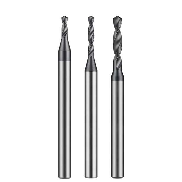
Tackling High L/D Ratios (5D/8D+): Chip Evacuation and Cycles for Long Drill Bits for Metal
When drilling depths exceed 5D, 8D, or 15D+, cutting mechanics deteriorate rapidly. Slender tool bodies lose flexural rigidity at a cubic rate, making them prone to centrifugal whipping at high spindle speeds. In deep holes, chips must be tightly curled and broken immediately at the cutting lips to prevent severe flute packing.
When helping heavy equipment and hydraulics shops set up deep-hole jobs, we always prioritize vibration dampening before chip evacuation. Deep-hole drilling requires a strict process chain, from pilot hole prep to stepped RPM entry cycles. Choosing dynamic-balanced long drill bits for metal with mirror-polished flutes is critical for maintaining hole straightness and process safety.
Overcoming Deflection: Pilot Hole Standards for Long Drill Bits for Metal
Most deep-hole wandering or entrance chipping happens when an operator skips the pilot hole or uses the wrong pilot tool. For drills past 8D, plunging a flexible tool directly onto a raw surface causes instant lateral deflection and hole misalignment. We mandate using a rigid, stubby 1.5D to 2D drill to establish an accurate guide hole first.
The pilot drill’s point angle must be equal to or slightly larger than the long drill (e.g., a 142° pilot followed by a 140° deep drill). Enter the pilot hole at 300 to 500 RPM with the coolant off. Once your long drill bits for metal are seated inside the pilot guide, turn on high-pressure coolant and ramp up to full cutting speed.
G83 vs. G73 Cycles: Resolving Torsional Failure in Long Drill Bits
A Wisconsin agricultural equipment plant had recurring tool breakage while drilling 10D oil holes in 42CrMo forgings. Their CNC program used a standard G73 high-speed peck cycle with a 0.020″ (0.5 mm) retract. The minimal peck failed to clear the chips, which packed tightly into the flutes, blocked the internal coolant, and snapped the tool.
We rebuilt their program using a progressive G83 deep-hole cycle. The tool drilled the first 3D depth in a single pass before switching to decreasing peck depths with full retracts to the pilot plane. This allowed coolant to flush out packed swarf, preventing long drill bits from binding and achieving an Ra 1.6 μm internal finish.
Controlling Runout to Within 0.003mm: Hydraulic and Shrink-Fit Tool Holders
In deep-hole drilling, any tool holder runout acts as a lever arm and magnifies tip wobble. Measuring 0.0004″ (0.01 mm) of runout at an ER collet face can amplify to over 0.0012″ (0.03 mm) at a 10D drill tip. This eccentricity overloads one cutting lip, unloaded the other, and creates severe radial chatter with bell-mouthed holes.
We strictly avoid worn mechanical collet chucks for deep drilling, requiring shrink-fit or high-precision hydraulic holders instead. Quality hydraulic holders lock total assembly runout under 0.003 mm with uniform 360-degree clamping pressure. Keeping runout minimal ensures balanced chip loads across both cutting lips, protecting long drill bits for metal from torsional fatigue failure.
Identifying True Grinding and QC Capabilities in Drill Bit Manufacturers
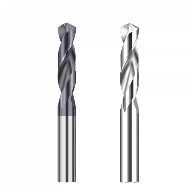
When evaluating tooling suppliers, buyers often get distracted by glossy catalog specs or low wholesale unit pricing. Having spent over sixteen years in tool manufacturing, we know tool performance is determined before the tool leaves the CNC grinder. Reliable drill bit manufacturers invest in climate-controlled grinding rooms and strict optical inspection to eliminate machine-side surprises.
Issues like built-up edge, corner chipping on tool steels, and deep-hole drift often stem from poor tool symmetry or inconsistent edge prep. If you want to improve process reliability, take a close look at your supplier’s quality control standards. Evaluating a vendor’s grinding hardware and inspection equipment reveals their true manufacturing capability.
Rod Stock Quality and 5-Axis CNC Grinding Standards in Drill Bit Manufacturers
Tool quality starts with raw material selection and grinding machine stiffness. Premium submicron carbide rods require homogeneous cobalt distribution and Hot Isostatic Pressing (HIP) to eliminate internal voids. Budget suppliers using scrap-recycled rods introduce internal defects that cause cutting lips to crack under cyclic impact loads.
Machining high-performance tools requires premium 5-axis CNC grinders (like Walter, Rollomatic, or Saacke) housed in temperature-controlled rooms. Professional drill bit manufacturers hold chisel edge symmetry, flute depths, and margin runout within a 2-micron window. Reliable suppliers provide non-contact optical inspection data proving the drill point’s symmetry axis aligns with the shank center line.
Microscopic Edge Honing Quality: Why Drill Bit Manufacturers Must Eliminate Burrs
A cutting edge straight off a grinding wheel looks razor-sharp to the eye, but 200x optical magnification reveals jagged, brittle grinding burrs. Applying PVD coatings over unhoned edges ruins coating adhesion. The micro-burrs snap off during the first cut, tearing away the coating layer and causing rapid flank wear within seconds.
When machining work-hardening stainless steels, always verify the edge hone radius (K-factor and ER value) on your tooling. Qualified drill bit manufacturers use wet blasting, nylon brushing, or drag finishing to generate a controlled 10 to 30 micron radius. This smooth edge transition eliminates stress risers without adding excessive axial thrust force.
Custom Step Drills: Supplying Job Parameters for the Ideal Drill Bit for Metal
Combining pilot holes, chamfers, and counterbores into a multi-step tool eliminates extra tool changes and reduces cycle times. However, custom tooling requires close alignment between the tool designer and the machine shop. Part prints showing only finished dimensions do not provide the full picture of machine-side cutting conditions.
If you plan to order custom step tools or special long-reach tooling, gather your shop-floor parameters first. Share your spindle taper, internal coolant pressure, workholding style, and whether you are cutting through mill scale or raw forgings. Supplying these details helps us engineer the ideal custom drill bit for metal with the right helix angles, flute transitions, and edge prep for your job.






