
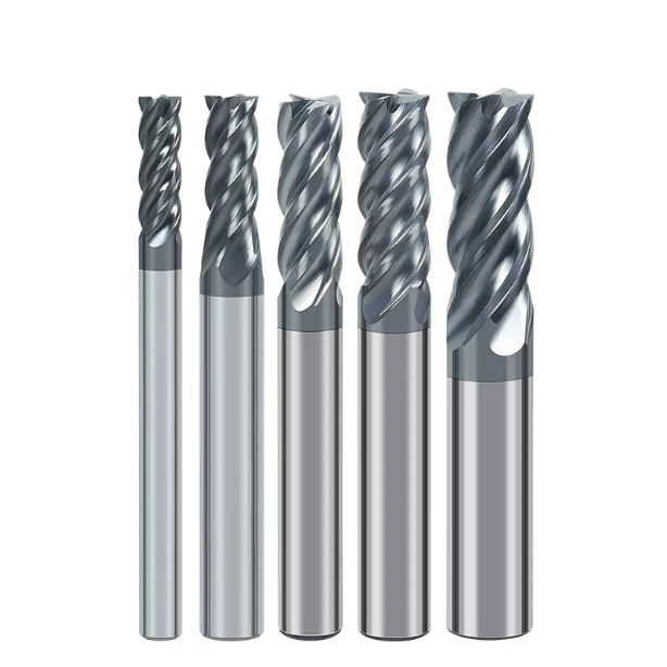
Last month, a long-standing German client contacted us with an urgent troubleshooting request. They were mass-producing 316L marine valve bodies on a 4-axis machining center, but their schedule stalled after switching to a low-cost tool supplier. Machine operators reported that while some tools ran smoothly for two hours, others suffered catastrophic tool breakage within fifteen minutes of slotting.
Under a stereomicroscope, the root cause was obvious: the microscopic edge preparation varied by 5 to 12 microns across the batch, and coating adhesion was unstable. Machining 316L requires managing poor thermal conductivity and severe work hardening. Using inconsistent tooling turns your production spindle into an expensive test bench.
Over a decade of manufacturing tools and supporting European and American machine shops has taught us that saving upfront on unit price often leads to costly scrap rates. Many procurement teams focus only on nominal carbide hardness or basic blueprint geometry. However, true tool life depends on core manufacturing factors:
- Substrate Grain Size and TRS: The fracture toughness of sub-micron carbide under heavy interrupted cuts.
- High-Temperature Coating Adhesion: The thermal barrier strength of multilayer AlCrN or AlTiN coatings under thermal shock.
- Batch Grinding Consistency: Total indicated runout (TIR), flute symmetry, and microscopic center-cutting quality.
- Application-Specific Geometries: Balancing feed rates, cutting speeds, and chip evacuation in 304, 316, or precipitation-hardened grades.
Faced with tight production schedules, how can shop engineers cut through supplier marketing claims and identify truly reliable milling cutters for stainless steel in high-volume orders?
Why Unit Price Isn’t the Only Factor in Bulk Milling Cutter Procurement: Lessons Learned from Shop-Floor Scrap Rates
When supporting machine shops, we often see purchasing teams divide large orders among low-bidding suppliers to trim upfront costs. While unit prices might drop by 20% to 30%, the shop floor pays the price. Operators end up constantly resetting tool offsets, untangling stringy chips, and fixing dimensional drift caused by excessive tool deflection.
Stainless steel generates high cutting forces and retains intense heat in the shear zone rather than dissipating it through chips. When low-cost wholesale milling cutters suffer from raw material impurities or uneven grinding, cutting forces quickly magnify these flaws. The money saved upfront is lost to scrapped parts and expensive machine downtime.
Three Hidden Pitfalls of Cheap Milling Cutter Bits in Batch Machining of 304/316 Stainless Steel
We have examined many failed budget milling cutter bits and identified three recurring failure modes in austenitic stainless steel. First, poor porosity control during tungsten carbide sintering causes low transverse rupture strength, leading to sudden shank fractures under heavy cut loads. Second, erratic manual or crude edge honing leaves micro-burrs that chip immediately upon hitting work-hardened surfaces.
The third issue is substrate annealing caused by inadequate coating thermal thresholds. Low-cost tools often use basic PVD coatings that oxidize below 800°C. When machining ductile 316 stainless, the coating quickly delaminates. Without this thermal barrier, the underlying carbide softens, the cutting edge collapses, and the tool fails prematurely.
Real-World Analysis by Western Clients: How “Cost-per-Edge” and Machine Downtime Determine True Procurement ROI
Two years ago, we helped an aerospace supplier in the U.S. Midwest evaluate tooling costs for hydraulic components. They were hesitant to invest in premium stainless steel end mills. We helped them implement a cost-per-edge formula that factored in cutting tool lifespan, setup labor, tool-setter wear, and shop downtime rates.
The results settled the debate: although the premium end mills cost 30% more upfront, their consistent batch quality extended tool life from 45 minutes to 110 minutes per edge. Spindle utilization rose by 12%, reducing the total tool cost per finished part by 18%. In production runs, process stability delivers real savings.
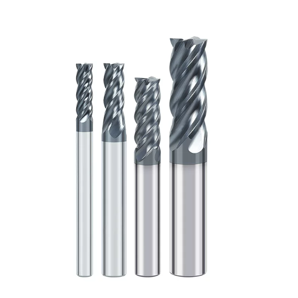
Carbide Substrate and Coating Inspection: How to Evaluate the Foundation of a High-Quality Stainless Steel Milling Cutter?
When diagnosing chipping or premature wear on the shop floor, the issue is rarely just programming paths or coolant flow. The performance of a high-performance milling cutter for stainless steel depends on the compatibility between the carbide substrate and its surface coating. Without a tough micro-grain core, even advanced coatings fail under cyclic cutting stress.
When vetting a cutting tool manufacturer, we evaluate their raw material quality and pre-coating preparation. Stainless steel work-hardens rapidly and maintains high strength at elevated temperatures. The tool substrate must absorb thousands of mechanical impacts per minute while the coating deflects heat past 900°C without flaking.
Selecting Carbide Rods: It’s Not Just About Specs—The True Balance of Sub-micron Carbide Between Mechanical Shock Resistance and Wear Resistance
We advise against automatically choosing ultra-fine or nano-grade carbide rods with hardness ratings above 93 HRA. In interrupted cuts and deep slots, harder substrates are more brittle. For materials that generate heavy chatter and plastic deformation, a sub-micron grain size (0.6 to 0.8 μm) with 10% to 12% cobalt provides the best balance of toughness and hot hardness.
When roughing forgings with heavy scale, trading some surface hardness for fracture toughness is the safer choice. In high-volume production, this substrate composition helps prevent catastrophic transverse breakage from chip packing, giving machine operators clear warning signs before total failure.
Real-World Comparison of High-Temperature Anti-Adhesion Coatings (AlTiN vs. AlCrN): Solving Coating Delamination Caused by Poor Heat Dissipation in Stainless Steel Machining
Many engineers default to standard AlTiN coatings, but we prefer AlCrN-based architectures for 316L or duplex stainless grades. While AlTiN works well in general dry cutting, its aluminum content can react with gummy stainless at elevated temperatures. This promotes built-up edge (BUE), which pulls the coating off the substrate when chips break away.
AlCrN coatings provide lower friction and better resistance to built-up edges. The dense chromium oxide layer withstands operating temperatures above 1000°C and resists abrasive wear. In wet machining or MQL setups, multilayer AlCrN cushions against thermal fatigue, preventing the micro-cracking that leads to coating spalling.
How to Specify Consistent Edge Honing Tolerances When Bulk-Purchasing Stainless Steel End Mills
When placing large orders for stainless steel end mills, specify an edge preparation tolerance range in your technical agreement rather than relying only on outer diameter specs. Unhoned razor edges contain microscopic fissures that chip instantly in work-hardened zones. Conversely, aggressive honing creates an oversized radius that increases cutting pressure and induces severe surface hardening.
For general milling and finishing in stainless steel, we control the micro-honed radius strictly between 8 and 15 microns, with batch variation held within ±2 microns. Request optical 3D cross-section inspection reports from systems like Alicona or Zoller. A uniform waterfall or micro-radius edge prep is what ensures predictable tool life across hundreds of parts.
Geometric Structure and Chip Evacuation Design: Manufacturing Details to Prevent Work Hardening and Chatter When Machining Stainless Steel
The piercing shriek of a machine spindle is an operator’s earliest warning sign when milling stainless steel. Cutting forces can run 40% higher than in standard steels, meaning improper tool geometry triggers high-frequency chatter. Once the flutes rub against the workpiece, severe work hardening takes over, causing accelerated flank wear and sudden edge chipping.
Overcoming this requires dialed-in micro-geometry rather than just playing with spindle overrides. During 5-axis tool grinding, subtle changes to rake angles, relief clearances, and flute cross-sections dictate how chips curl and forces disperse. These microscopic details allow a high-performance milling cutter for stainless steel to remain exceptionally stable during deep pocketing and heavy side cuts.
Variable Helix and Pitch: The Key to Eliminating Chatter in 316L Deep-Cavity Milling
If sidewall chatter marks are ruining your 316L deep pockets, inspect your tool’s helix and pitch configuration. Standard tools with symmetrical flutes hit the cut at fixed intervals, creating a uniform harmonic frequency. In extended-reach setups, this vibration quickly amplifies, leaving visible ripple patterns and chipping the corners of your cutting edges.
We resolve this by grinding an asymmetrical geometry featuring variable helix angles (like 35°/38°) paired with unequal flute spacing (such as 88°/92°). This structure breaks harmonic resonance by staggering the impact phases across the cut. In real-world 316L pocketing, this variable design eliminates surface ripples and lets you push axial depths of cut 20% deeper without backing off your feeds.
Slotting vs. High-Feed Side Milling: Trade-offs in Chip Pocket Volume and Core Thickness for Stainless Steel Milling Cutters
Choosing between 4-flute and 5-flute tools comes down to balancing chip evacuation space against core rigidity. Stainless produces stringy, ductile chips that weld together if packed into a slot. For 1xD full-slotting, a 4-flute milling cutter for stainless steel is ideal because its deeper flutes give chips room to curl and eject freely without re-cutting.
For high-efficiency side milling and dynamic trochoidal paths with low radial engagement (Ae), a 5-flute tool with a heavy core (55% to 60% of cutter diameter) is far superior. The thicker web resists bending forces, eliminating wall taper and dimensional drift. Combined with polished U-shaped flutes, chips clear smoothly under high feed rates, maximizing metal removal rates.
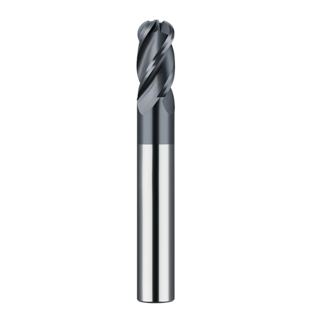
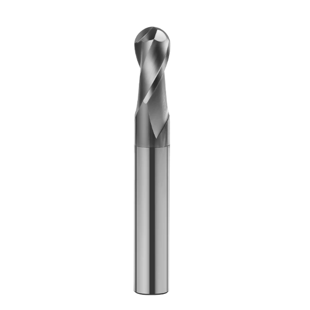
Surface and Mold Machining Special: A Checklist for Avoiding Pitfalls When Bulk-Sourcing Ball Nose End Mills for Stainless Steel
Contouring stainless medical implants and aerospace impellers is the ultimate proving ground for high-precision tooling. Unlike flat tools, ball nose end mills for stainless steel must deal with cutting speeds that drop to zero right at the center tip. This physical limit requires exceptional hemispherical grinding precision and superior center-edge support to prevent immediate breakdown.
When bulk-purchasing ball nose cutters, many buyers inspect outer diameters while ignoring spherical profile accuracy and center-gash symmetry. Stainless steel work-hardens rapidly under compressive loads. Any distortion in the tip profile causes uneven scallop heights during 3D blending passes, leaving poor finishes that force shops into expensive, manual bench polishing.
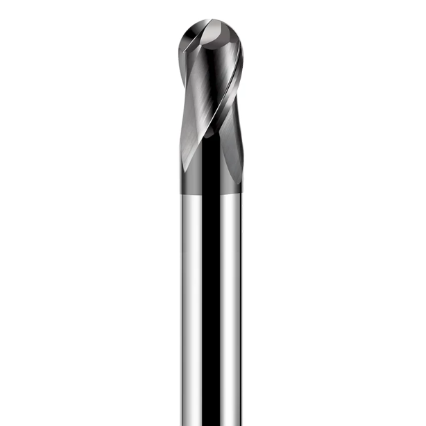
Center-Edge Toughness in 3D Profiling: Why Do Many Ball Nose CNC Milling Cutters Chip Prematurely During Plunge Milling?
When troubleshooting 3D surfacing failures, we often see a standard ball nose cnc milling cutter fracture right at the tip during vertical plunges or steep ramps. Because surface speed drops to zero at the tool’s rotational axis, the cutting action turns into pure material compression. Gummy stainless gets crushed into the center dead zone, generating huge axial forces.
To counter this, we grind an S-shaped cross-split or eccentric relief directly into the center cutting gash. This geometry reinforces the microscopic web thickness and creates a smooth exit path for trapped chips. In your CAM setups, always favor helical ramping or ramping angles under 3° over straight vertical plunges to keep cutting forces on the active cutting edges.
Minimum TIR Tolerance Standards for High-Precision Ball-Nose End Mills (for Stainless Steel) in 5-Axis Impeller and Flow Channel Machining
In 5-axis machining of 17-4 PH impellers and fluid ports, continuous tool axis tilting magnifies every microscopic mechanical error. For high-volume orders of ball nose end mills for stainless steel, we hold radial Total Indicated Runout (TIR) within 0.003 mm (0.00012″), with the spherical profile envelope locked within ±0.005 mm across the entire radius.
If runout drifts beyond these limits during tilted cuts, a single cutting edge bears the entire cutting load while the opposite flute merely rubs. This uneven stress causes rapid chipping on one side and gouges delicate thin-walled blades. Always mandate verified runout reports from non-contact laser or optical presetting systems before approving volume shipments.
Controlling Tool Marks in Ball-Nose Root Cleaning and Deep Cavity Transitions: Optimizing Rigidity via Tapered Shanks and Long-Neck/Short-Flute Designs
Cleaning out deep corner radii often leads to deflection marks and chatter when using standard, full-flute-length tools. Long cutting flutes drastically reduce cross-sectional stiffness in stainless steel. Even light cutting pressure causes the tool to flex, resulting in visible mismatch steps and gouging where tool paths overlap.
We recommend using long-reach, short-flute tools or stepped shanks with tapered necks. By keeping the active cutting length short (2xD to 3xD) and relieving the neck diameter behind it, you maintain maximum shank rigidity while preventing sidewall rubbing. This setup suppresses tool deflection, delivering seamless blending steps across complex finishing passes.
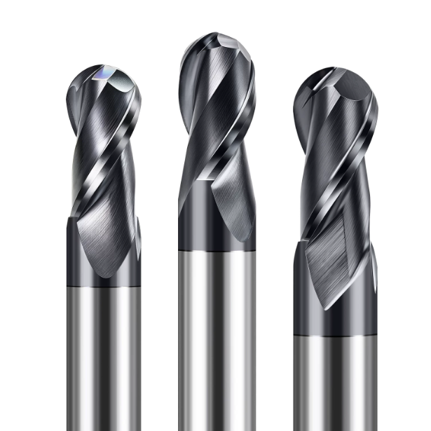
Can Manufacturer Parameters Be Used Directly? Real-World Testing of End Mill Speeds and Feed Rates for Stainless Steel
Tool selection catalogs near machine panels are a familiar sight, but copying catalog speeds into your CAM software often causes premature failure. Published data for end mill speed for stainless steel reflects ideal lab conditions with high-rigidity spindles, zero runout, and short tool overhangs. Real-world setups must account for spindle aging, fixture vibration, and toolholder balance.
Machining stainless steel requires balancing surface speed against chip load to avoid overheating. Excessive spindle speed traps intense heat in the cutting zone, degrading the coating and softening the carbide. Conversely, running low speeds with inadequate feed causes rubbing and burnishing. Fine-tuning parameters by listening to spindle harmonics and inspecting chip color is an essential shop-floor skill.
Why Blindly Following Catalog Recommendations for Stainless Steel End Mill Speeds Leads to Work Hardening
When encountering tool failure, operators often increase spindle speed and reduce feed per tooth to “take lighter cuts.” This mistake is devastating in stainless steel. If the feed per tooth (fz) drops below the edge honing radius, the flutes cannot shear under the material’s grain boundaries. Instead, the cutting edge rubs against the work-hardened layer left by the previous pass.
This rubbing spikes surface hardness and generates severe friction heat. Relying on generic recommendations for end mill speed for stainless steel without sufficient feed per tooth leads to rapid notch wear and chipped edges. In production runs, it is far better to lower surface footage slightly while maintaining a healthy chip load that slices through the hardened skin and carries away heat.
Guidelines for Adjusting Cutting Speed (SFM/Vc) and Feed per Tooth (fz) for Austenitic (304/316) and Precipitation-Hardening (17-4 PH) Stainless Steels
Different stainless grades require tailored cutting parameters rather than a generic formula. For gummy austenitic grades like 304 and 316, we recommend a cutting speed (Vc) of 80 to 140 m/min (260 to 460 SFM) and a feed per tooth (fz) of 0.03 to 0.08 mm/tooth. This window ensures clean shear plane formation and prevents chips from packing the flutes.
For aged 17-4 PH or 15-5 PH (HRC 36–44), high shear strength substantially increases tool pressure. We reduce cutting speeds to 50–90 m/min (160–300 SFM) to mitigate thermal shock along the cutting edge. Pairing a tough, small-rake stainless steel end mill with high-feed, shallow-depth profiling protects the cutting corners against brittle micro-fractures.
Extending Tool Life by Over 40% via Speed Fine-Tuning in High-Pressure Coolant and Trochoidal Milling Operations
Dynamic trochoidal milling combined with high-pressure through-spindle coolant (TSC) has revolutionized stainless milling. In trochoidal paths, radial engagement (Ae) is kept low—typically 5% to 10% of tool diameter. The brief engagement arc gives cutting edges ample time to cool during non-cutting rotation, preventing heat accumulation.
Because thermal build-up is minimized, you can safely increase your end mill speed for stainless steel by 30% to 50% (reaching over 180 m/min in 304). High-pressure coolant (70+ bar) fractures chips instantly and blasts them out of the cut. This eliminates chip re-cutting, stabilizes substrate temperatures, and extends batch tool life by over 40%.
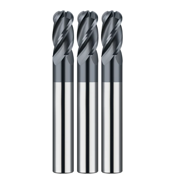
Acceptance Guide for Western Buyers: Key Criteria for Evaluating High-Reliability Stainless Steel End Mill Manufacturers
Micro-grain selection, AlCrN adhesion, unequal helix geometries, and feed optimization all depend on one factor: manufacturer process control. When evaluating a supplier for high-performance stainless steel end mills, look past glossy product brochures and test samples. True manufacturing competence lies inside the grinding facility and quality lab.
If you are sourcing tooling for high-volume stainless production, evaluate machine tool accuracy, inspection protocols, and technical responsiveness. When a manufacturer combines top-tier CNC grinding equipment with experienced application engineers, your machine shop avoids costly scrap and unplanned downtime during demanding production runs.
Key Benchmarks for 5-Axis Tool Grinding Equipment and Inspection Instruments
To evaluate a cutting tool manufacturer’s technical capabilities, request a list of their production and metrology equipment. Grinding micro-edge profiles and complex flutes demands high machine repeatability and thermal stability. Premium 5-axis CNC tool grinders from builders like Walter, Rollomatic, and Schneeberger are the industry baseline for batch uniformity.
Equally important is comprehensive post-grinding optical metrology. Require suppliers to provide inspection reports from non-contact measurement systems like Zoller or Alicona with every shipment. These reports should verify outer diameter, flute spacing symmetry, and edge hone radii across the entire batch before tools reach your spindle.
Consistency Control from First-Article Inspection (PPAP) to Bulk Shipment (Runout Controlled Within ±0.003mm per Batch)
Many machine shops experience flawless initial test samples followed by inconsistent production shipments. When sourcing wholesale milling cutters, require suppliers to follow PPAP principles and verify statistical process capability (Cpk). Grinding cells must incorporate automated wheel dressing and in-process thermal compensation to hold total indicated runout (TIR) within ±0.003 mm across the run.
In batches of hundreds or thousands of end mills, excessive runout causes single-flute overloading during multi-axis profiling. If your shop records show sporadic chipping or dimensional drift, inconsistent batch tolerances are the likely culprit. Implementing strict spot-check limits and individual laser-etched tracking codes ensures consistent tool life.
Sourcing Direct Manufacturers for Application-Specific Customization and On-Site Technical Support
If you are tackling difficult bottlenecks—such as deep pockets in 17-4 PH, miniature medical parts, or duplex slotting—partner directly with a primary grinding facility rather than a catalog distributor. Standard catalog tools are designed for general applications. Under extreme conditions, adjusting the rake angle by 2°, modifying core thickness, or adding reach necking solves chatter and chip-clearing issues.
A qualified cutting tool manufacturer should act as an extension of your engineering team. When dealing with work hardening, visible blend marks, or premature edge wear, share your part tolerances, fixture rigidity, and current feeds and speeds. Collaborating directly with tool engineers who understand cutting mechanics delivers real gains in shop-floor throughput.






