
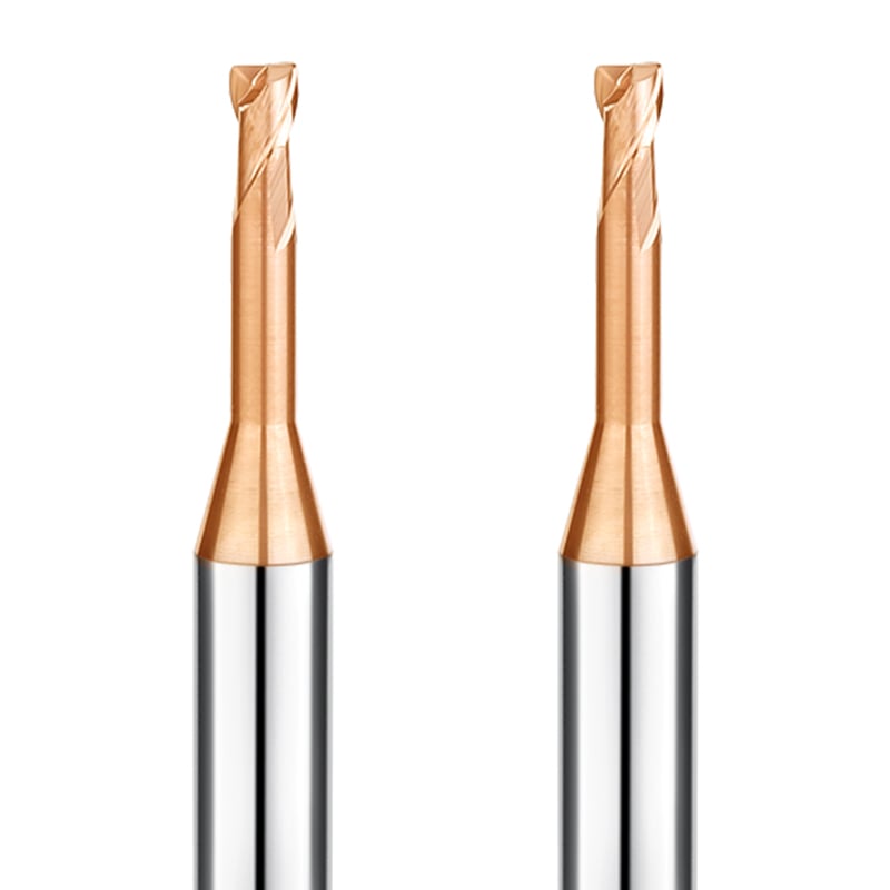
Last month, we received an urgent call from the technical lead of a German contract machine shop. They had just launched a production run of 316L aerospace structural frames on a 4-axis machining center. Less than two shifts in, flank wear across their entire tool inventory spiraled out of control. Operators had to constantly offset tools and back off feed rates, slashing effective spindle output by half.
When they sent over photos of the worn cutting edges along with their procurement specs, the root cause was obvious. The issue was not machine rigidity, fixture stability, or coolant delivery. They had simply walked into one of the most expensive selection traps when purchasing a milling cutter for metal.
We see this exact scenario play out almost monthly across European and US job shops. Tool buyers often get misled by catalog ratings and standard data sheets:
- Fixating on unit price and nominal hardness: Assuming sub-micron carbide grades and high surface ratings work everywhere, while ignoring transverse rupture strength (TRS) under interrupted cuts.
- Defaulting to generic PVD coatings: Running standard carbon-steel coatings on nickel-based alloys, triggering rapid heat buildup and coating delamination.
- Mismatched core diameter and flute space: Running high-tooth-count tools in enclosed slots, leading to immediate chip packing and edge chipping.
True tooling cost is rarely determined by the line item on an invoice. It is measured in ruined workpieces, spindle idle time, and unscheduled tool changes. Over the past 16 years of engineering custom tooling and solving shop-floor failures, we have documented the most critical purchasing errors.
When you faced unexplained chatter marks or erratic edge life last month, did you ever suspect the issue started the moment the purchase order was signed?
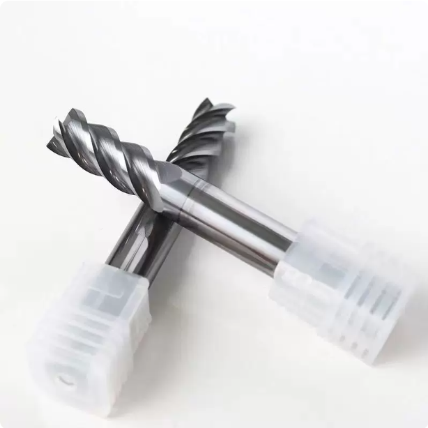
Mistake #1: Blindly Prioritizing Hardness and Choosing the Wrong Substrate for Carbide Milling Cutters
When reviewing tooling sheets from customer shops, we constantly see procurement teams treat substrate hardness as the sole indicator of cutter quality. Many supervisors order ultra-hard grades under the assumption that maximum hardness solves all wear problems across steels and alloys.
In our cutting trials and field tests, pushing hardness too high almost always backfires on interrupted cuts. Raising carbide hardness demands lowering cobalt content, which drastically cuts the material’s impact toughness. Once cutting dynamics shift from smooth cuts to mechanical shock, fragile carbide milling cutters fail rapidly at the spindle.
Harder Is Not Always Better: Why We Advise Against Ultra-Fine Substrates in Superalloys
While helping a French aerospace subcontractor mill deep pockets in Inconel 718, their team insisted on using ultra-fine sub-micron grade cutters. Their logic seemed sound: high-temperature alloys generate extreme heat, so they wanted dense carbide to fight abrasive wear. Instead, the cutting edge micro-chipped on the very first pass and blew out entirely two minutes later.
We halted the cut and swapped in a medium-grain substrate with two percent higher cobalt content. Nickel alloys work-harden aggressively, generating violent cyclic shock waves rather than steady abrasion. Sacrificing a fraction of theoretical hardness gives your carbide milling cutters the baseline fracture toughness needed to survive these thermal and mechanical spikes.
Troubleshooting Breakage in Western Shops: Matching Chip Load to Transverse Rupture Strength
A large injection mold facility in Michigan recently contacted us regarding severe lateral tool breakage in pre-hardened 42 HRC steel. The operator took an aggressive radial width of cut (ae) to clear a pocket corner quickly. This produced thick chip ribbons that failed to clear and packed tightly into the secondary cut zone.
The resulting chip re-cutting forces instantly smashed past the transverse rupture strength limits of standard hard carbide milling cutters. Rather than dropping the feed, we switched them to a high-TRS substrate with reinforced edge prep to handle the shock. When facing unpredictable tool fractures on your floor, verify whether your substrate toughness matches your actual chip load dynamics.
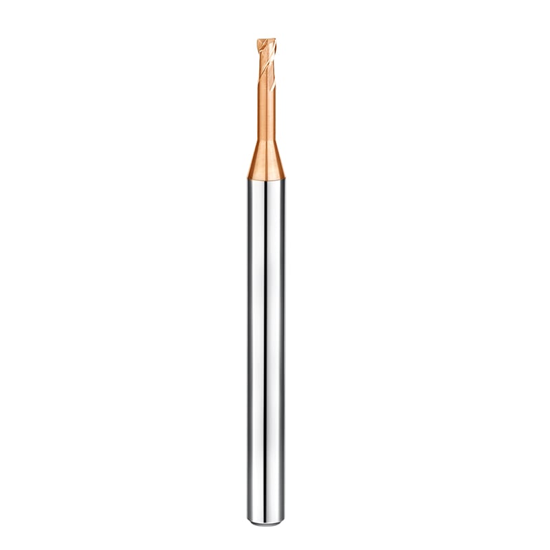
Mistake #2: Ignoring Chip Evacuation and Rigidity Balance Across Different End Mill Types
Machinists often blame poor finishes or tool breakage on machine spindle rigidity, but the real bottleneck is frequently flute geometry. Operators routinely grab standard general-purpose tools without balancing chip clearance against core thickness. Increasing flute gullet depth weakens the core diameter, while expanding the core chokes off the chip exit path.
Selecting the wrong geometry from available end mill types causes immediate failures in closed slots or deep pockets. Chips pack tightly inside the flutes, welding themselves to the cutter body and causing instant breakage. Even a small miscalculation in radial engagement can cause severe tool deflection and heavy chatter marks on side walls.
The Pitfalls of 2-Flute, 3-Flute, and Multi-Flute Tools: Lessons from Sticky Aluminum and Stainless Steel
While troubleshooting 316L deep slotting at a UK medical device shop, we found the team running 5-flute tools to push higher table feeds. Austenitic stainless steel produces stringy, expanding chips that quickly choked the narrow flute valleys, causing the spindle load meter to spike instantly. Among standard end mill types, multi-flute tools belong strictly in open-air peripheral milling where chips can escape freely.
Machining gummy aluminum requires the opposite strategy. We recently helped an automotive supplier double their feed rates by swapping 4-flute cutters for 2-flute and 3-flute polished geometry. The massive chip pockets eliminated chip packing, allowing much higher spindle speeds. Matching your flute count to material chip morphology matters far more than simply maximizing the number of teeth.
Rigidity in Flat, Ball, and Radius Geometries: Protecting Margins in Deep-Cavity Mold Work
At the cutting tip, geometry dictates structural tool life far more than coatings do. A Swiss mold shop we supported kept chipping sharp 90-degree square cutters while clearing internal pocket corners, leaving ugly witness steps along cavity walls. Sharp square tips create localized stress concentration zones that cannot withstand sudden tool load spikes in tight internal corners.
We solved the issue by switching them to corner-radius bull-nose end mill types with an R0.5 corner prep. The small corner radius spreads cutting forces along an arc rather than focusing stress onto a single point. Unless your blueprint strictly demands an absolute square corner, running a radius tool is the single best way to stabilize tool life in deep cavities.
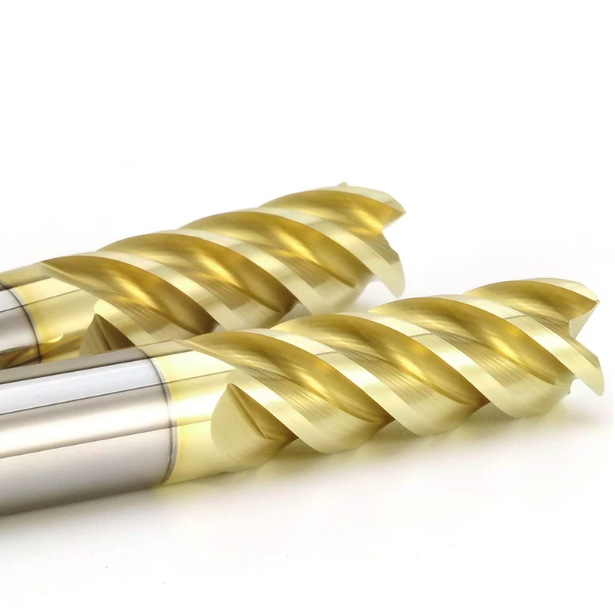
Mistake #3: Relying on a “One-Size-Fits-All” Coating and Ignoring Chemical Wear in Metal Milling Cutters
In many machine shops, operators run the same dark purple or copper-colored cutter on everything from 1045 steel to nickel-based superalloys. Purchasing agents assume high-hardness PVD coatings act like armor against all types of friction. In reality, a coating functions primarily as a thermal barrier to prevent extreme interface heat from degrading the tungsten carbide core.
During high-speed cuts, shear-zone temperatures routinely exceed 800°C, triggering aggressive elemental diffusion between the tool and the workpiece. Selecting a generic metal milling cutter without matching coating chemistry to workpiece metallurgy causes rapid layer delamination. When chemical affinity takes over, even thick coatings strip away in minutes.
Why the Same Metal Milling Cutter Fails Prematurely on Titanium yet Excels in Carbon Steel
While helping an Italian valve manufacturer troubleshoot aerospace components, we saw this failure mechanism firsthand. The shop used an AlTiN-coated metal milling cutter on 4140 steel with outstanding tool life. However, when running the exact same tools on Ti-6Al-4V titanium, the flank coating peeled within ten minutes, rapidly degrading the cutting edge.
Under SEM and EDS analysis, the failure mechanism was clear. AlTiN forms a protective aluminum oxide film when cutting steel, but titanium’s poor thermal conductivity traps extreme heat at the shear zone. This triggers a chemical reaction between the aluminum in the coating and the titanium substrate. Never rely solely on room-temperature hardness ratings; chemical stability at elevated cutting temperatures determines actual tool survival.
Assessing Cutting Temperatures and Coolant Strategies to Select the Optimal Coating
When formulating tooling recommendations, we always verify the shop’s cooling medium and chip evacuation setup first. For high-speed dry milling in hardened tool steels above 50 HRC, we specify silicon-doped nanocomposite coatings like AlTiSiN. These withstand oxidation past 1100°C and force thermal energy away from the tool and directly into the departing chips.
Wet machining environments require a completely different approach. Intermittent flood coolant creates severe thermal cycling, causing micro-cracking across brittle, high-heat coatings. In flood or high-pressure oil setups, choosing a tough metal milling cutter with low internal coating stress prevents thermal shock. Always evaluate whether your coolant setup is actively dissipating heat or creating a thermal shock trap at the tool tip.
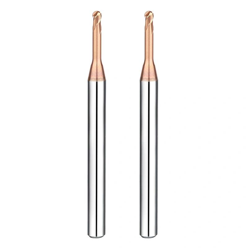
Mistake #4: Treating the 8mm Metal Milling Cutter as a Universal Tool and Exceeding Overhang Limits
In small and mid-sized job shops, the 8mm size is almost always the most stocked item in the crib. Machinists rely on it for slotting, profiling, and clearing small pockets. However, operators often forget the cubic deflection rule: radial deflection increases with the cube of the overhang length, while stiffness scales with the fourth power of the cutter diameter.
As cavity depth increases, extending tool stick-out by even 10mm causes structural rigidity to drop sharply. Forcing a standard 8mm metal milling cutter into deep pockets causes spring pass deflection, dimensional taper errors, and severe chatter marks. Without accounting for length-to-diameter ratios, high-efficiency machining becomes impossible.
Troubleshooting 8mm Metal Milling Cutter Chatter: Clamping Rigidity and Stick-Out Errors
Last year, a Swedish hydraulic valve manufacturer asked us to resolve chronic surface finish issues on internal cavity walls. Operators ran a standard 8mm metal milling cutter extended nearly 50mm out of an ER collet chuck to clear fixturing. Radial runout measured at the cutting tip exceeded 0.015mm, leaving heavy fish-scale chatter across the part.
We solved the issue immediately by switching them from standard ER collets to balanced shrink-fit holders. We also swapped the standard end mill for a short-flute cutter with a reinforced, relieved neck. Before dropping feed rates to suppress chatter, check your toolholder rigidity and minimize stick-out first.
Managing Deflection and Cutting Depths (ap / ae) in 8mm Slotting and Dynamic Toolpaths
Different toolpath strategies place distinct structural loads on an 8mm cutter body. In full-slotting cuts (1.0D), we advise capping axial depth of cut (ap) at 0.5D to prevent flute packing and core fracture. In high-efficiency dynamic milling with radial engagement (ae) at 5% to 10%, cutting forces convert mostly into lateral deflection loads.
Pushing radial step-over too hard during dynamic milling causes elastic tool push-off without immediate breakage. This deflection leaves uneven stock allowances along vertical walls, creating severe taper errors for the subsequent finishing pass. When pushing an 8mm metal milling cutter, you must balance your programmed step-over against cutter core deflection.
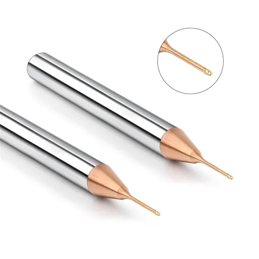
Mistake #5: Focusing on Purchase Price Over Cycle Times with an End Mill Milling Cutter
When reviewing tooling tenders, procurement teams often compare identical catalog specs and award orders to the lowest bidder. On paper, saving 20% to 30% on consumable costs appears efficient. However, tooling purchases typically represent only 3% to 5% of total manufacturing costs in a modern CNC machine shop.
Choosing a budget end mill milling cutter with inconsistent batch tolerances quickly erodes upfront savings on the shop floor. Lower-grade tools cause erratic flank wear, frequent tool-offset adjustments, and unexpected tool breakage. The resulting spindle downtime and scrap parts cost far more than any initial tooling discount.
How a Low-Cost End Mill Milling Cutter Cost an Ohio Machine Shop Thousands in Scrap
An Ohio facility manufacturing aluminum sensor housings ran into trouble when shipping delays led them to buy cheap replacement cutters. While initial cuts sounded clean, inconsistent edge preps and poor substrate quality degraded tool life rapidly. Operators were forced to stop machines every two hours to touch off tools and update offsets.
The frequent tool retractions left visible witness steps across tight-tolerance mating surfaces, causing CMM inspection failures across the batch. The shop saved $12 per tool but scrapped over 60 precision components, costing more than $7,000 in lost production and weekend overtime. Buying a cheap end mill milling cutter often trades minor invoice savings for massive losses in spindle efficiency.
Calculating Real Shop-Floor Value: Evaluating Tooling TCO Through Cycle Time and Part Yield
When structuring production runs, we measure tooling performance through Total Cost of Ownership (TCO), prioritizing cycle time reduction and metal removal rates. A premium tool may cost twice as much, but if its rigid core and smooth flutes allow 30% higher table feeds, total manufacturing costs drop substantially.
Machining profitability depends on how many in-spec parts a spindle produces per hour, not initial tool cost. Running an optimized end mill milling cutter cuts cycle times and frees up valuable spindle hours on expensive multi-axis machines. Before approving a purchase order based solely on unit price, calculate the true hourly cost of spindle downtime and frequent tool resets.
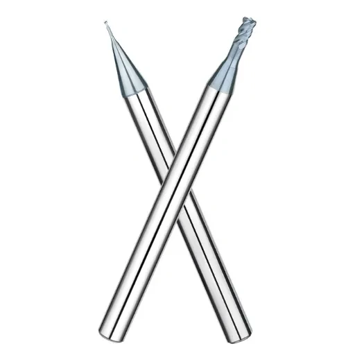
Mistake #6: Confusing Roughing and Finishing Requirements with an End Mill Milling Cutter
In many shop schedules, programmers take a shortcut by using a single cutter for an entire cycle. To eliminate tool changes, they run an asymmetric anti-vibration tool across everything from rough forged scale down to final critical wall passes. This workflow ignores the opposing physics of heavy metal removal versus micro-finishing.
Roughing demands massive chip pocket clearance and impact toughness to handle heavy radial stock. Finishing requires sharp cutting edges, low cutting resistance, and minimal tool deflection. Forcing a specialized end mill milling cutter designed for harmonic chatter suppression into heavy roughing overloads the flutes, rapidly destroying precision edge prep.
Why Variable Pitch and Asymmetric Geometry Fails in Heavy Roughing Cuts
While auditing a Belgian agricultural equipment manufacturer, we saw operators roughing 42CrMo forgings on an older three-axis mill with spindle play. They used a premium variable-helix end mill milling cutter for full-width slotting. The spindle growled under load, and after two passes, the secondary cutting edge chipped away, leaving chatter waves across the forged link.
Variable pitch designs disrupt harmonic resonance frequencies during light-to-medium radial engagement, but they require a rigid machine platform. Under heavy roughing loads, cutting forces exceed the tool’s harmonic damping capacity. Using an asymmetric finishing tool to plow through heavy scale wastes tool budget and accelerates spindle bearing wear.
Process Handover: Roughing Wave Cutters to Precision End Mill Milling Cutter Finishing
High-efficiency milling relies on strict separation between roughing and finishing passes. Running a wave-edge rougher slices broad chips into small, manageable segments, slashing radial tool pressure on lower-horsepower machines. Once bulk material is cleared, establishing a uniform, predictable finishing stock allowance protects final part accuracy.
We advise setting your radial finishing stock between 1% and 3% of cutter diameter (about 0.1mm to 0.2mm on a 10mm tool). If the previous roughing pass leaves irregular stock steps, lateral load fluctuations will deflect your end mill milling cutter, causing witness marks on finished walls. Always leave a clean, uniform stock layer for your final finishing pass.
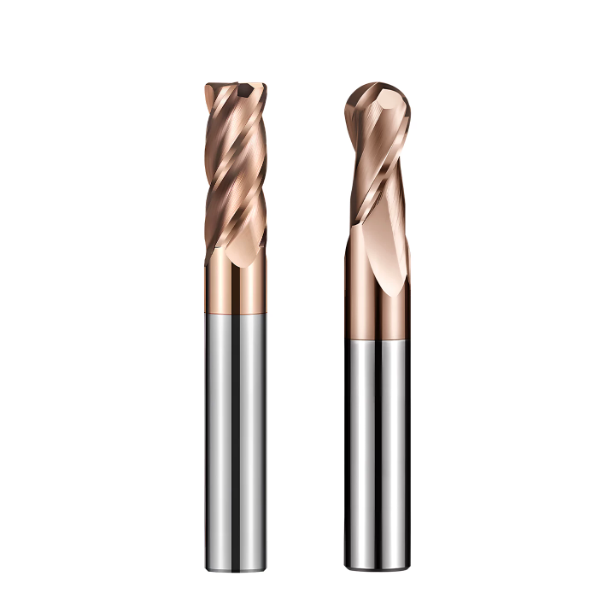
Mistake #7: Sourcing from Middlemen Instead of Direct Carbide Milling Cutter Manufacturers
When troubleshooting production lines, erratic tool-to-tool consistency is far more damaging than standard abrasive wear. A trial tool may run cleanly at high feeds, while the reordered production batch chips prematurely. Machinists often blame machine fixtures or CAM toolpaths, overlooking hidden risks in their tool procurement channels.
Distributors frequently split large purchase orders across different job-shop grinders to widen margins, causing major batch-to-batch variations in flute geometry and edge honing. Sourcing directly from certified carbide milling cutter manufacturers ensures strict substrate traceability, temperature-controlled 5-axis grinding, and consistent coating adhesion across every single order.
How Tool Tip Runout Exceeding 0.005mm Triggers Edge Chipping in Production
A Spanish automotive supplier machining engine blocks experienced sudden edge chipping and a 60% drop in tool life on a new order of four-flute end mills. Using optical measurement at the machine spindle, we discovered tip runout ranged between 0.008mm and 0.012mm—well outside acceptable precision tolerances.
When runout exceeds 0.005mm, multi-flute tools effectively cut on only one or two teeth, doubling chip load on a single cutting edge and triggering rapid edge fracture. Reliable carbide milling cutter manufacturers enforce automated optical inspection and dynamic balancing to lock total indicated runout (TIR) under 0.003mm out of the box.
Developing Custom Step and Form Tools with Dedicated Carbide Milling Cutter Manufacturers
Prototyping custom multi-step form tools through third-party distributors often results in severe communication breakdowns. A North American hydraulics plant spent two months and three failed revisions on custom spool cavity tools because a broker omitted critical drawing callouts for step relief clearance and internal coolant hole locations.
Once their engineering team contacted our manufacturing floor directly, our tooling designers optimized the relief angles, internal coolant channels, and step transitions within forty-eight hours. The updated tool passed CMM inspection on the very first pass. Partnering directly with carbide milling cutter manufacturers eliminates communication gaps, protects print tolerances, and shortens cycle times on non-standard tooling.






