
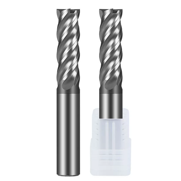
Last month, we received an urgent email from a long-standing customer in Ohio. Their shop was batch-machining 316L stainless steel valve bodies for food-grade fluid systems, but their production line ran into severe trouble.
When pocketing and cutting full-width deep slots, the operators used the same 4-flute tools that had delivered excellent results during sidewall profiling. After fewer than eight parts, the spindle load spiked, accompanied by a piercing screech from the enclosure. The cutters snapped at the slot corners, with the fracture points caked in melted chips. Switching to generic square-end mills stopped the breakage, but severe chatter marks on the outer profiles pushed the surface roughness out of tolerance.
As cutting tool manufacturers with over 15 years of experience on the grinding floor, we have seen this scenario play out across countless machine shops. Machinists often select general end mill bits for stainless steel based only on the workpiece material, overlooking the distinct mechanical demands of specific toolpaths. Stainless steel has poor thermal conductivity, high shear strength, and work-hardens rapidly.
In full-width (1.0xD) slotting, the main engineering bottleneck is balancing chip evacuation volume against available flute space. During profile milling, the priority shifts to core rigidity and deflection resistance. Choosing the right cnc milling cutters means finding the balance between chip pocket volume and cross-sectional stiffness. So, where is the boundary where you must switch from 2 flutes to 4 flutes?
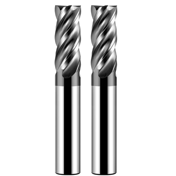
Why Stainless Steel Machining Defies a “One-Size-Fits-All” Approach: Real-World Tool Failures Observed in CNC Workshops Across Europe and North America
Over the years, we have visited dozens of production facilities across North America and Europe, from automated plants in Bavaria to job shops in the Great Lakes region. When troubleshooting tool failures, we consistently find piles of scorched, discolored end mills in scrap bins. Operators often blame poor PVD coatings or machine rigidity, but the real issue is usually a mismatch between the cutting strategy and tool geometry.
Stainless steel creates high cutting temperatures and work-hardens instantly under friction. Trying to use a single tool geometry for both heavy slotting and fine contour finishing pushes the carbide beyond its physical limits. We often remind shop supervisors that shortcuts taken to avoid tool changes usually backfire, leading to premature tool wear, erratic part tolerances, and costly machine downtime.
The Root Cause of Tool Breakage and Work Hardening in Western Workshops: Incorrect Flute Count Selection for Slotting and Side Milling
During a project with a UK aerospace contractor machining 316L brackets, we observed a classic process mistake. To eliminate a tool change, they programmed a standard 4 flutes end mill for stainless steel to plunge-cut deep, enclosed slots at full tool diameter. Because the flutes were narrow, high-pressure coolant could not flush the swarf away. Red-hot chips packed into the gullets, underwent secondary shearing, and snapped the tool corners within seconds.
When the shop switched to a 2-flute tool to finish the outer walls, the reduced core diameter caused excessive radial deflection. The cutting edges rubbed and pushed against the sidewall instead of shearing cleanly, creating a severe work-hardened layer. When the next flute engaged the hardened surface, cutting forces spiked, resulting in heavy chatter and ruined surface finishes.
The Physical Trade-off Between Chip Gullet Volume and Core Rigidity: The Fundamental Balance in CNC Milling Cutters for Stainless Steel
When grinding dedicated tools on our 5-axis CNC tool grinders, our design work centers on an uncompromising physical trade-off. Producing high-performance cnc milling cutters requires balancing chip pocket volume against the central core diameter. If you grind deep flutes to ensure smooth chip evacuation, you sacrifice structural core thickness and bending resistance.
Conversely, expanding the core thickness beyond 60% of the cutter diameter resists lateral deflection during heavy side cuts, but it constricts chip evacuation channels. In full-slotting operations, ejecting chips in milliseconds prevents thermal expansion and tool binding. In contour profiling, high rigidity prevents taper and chatter, making this geometric trade-off the core criterion for tool selection.
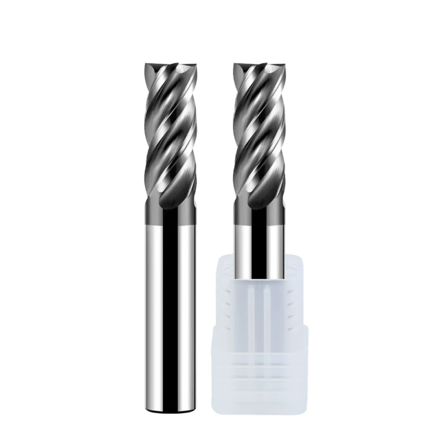
Slotting Operations—Why a 2-Flute End Mill for Stainless Steel Remains the Top Choice for Deep Slots and Cavities
In high-volume production, programmers often assume that higher flute counts and faster table feeds yield higher output. However, in enclosed slotting or pocket clearing with 100% radial engagement, this assumption causes problems. In our testing of a dedicated 2 flutes end mill for stainless steel, providing ample physical space for chip evacuation proved far more critical than adding extra cutting edges.
Tool life typically drops once slotting depth exceeds 1.0 to 1.5 times the tool diameter. In these cuts, the radial engagement arc reaches 180 degrees, keeping the cutting edge under constant mechanical load with limited coolant access. The generous flute valleys of a 2-flute design provide an open exit path for chips, making it the most reliable choice for deep slots in gummy alloys.
Chip Evacuation Challenges in Full-Width Slotting of 304/316L: How the 2-Flute Design Prevents Secondary Shearing and Built-Up Edge (BUE)
Machining austenitic grades like 304 or 316L produces ductile, stringy chips that weld easily under pressure. In full-width slotting, cutting zone temperatures quickly exceed 800°C. If the chip gullets are too shallow, hot chips become trapped between the tool body and the slot walls. These trapped chips re-weld to the cutting edge, forming a built-up edge that causes micro-chipping on the next rotation.
This is where specialized stainless steel milling cutters prove their worth. By grinding wide, polished parabolic flutes, chips curl and eject smoothly the instant they shear from the workpiece. Removing chips quickly carries away over 70% of the cutting heat, preventing chip recutting and localized heat buildup while maintaining consistent spindle load throughout the cut.
Real-World Case Study: Tool Breakage Rate Dropped to Zero After Switching a German Medical Component Client from 4-Flute to 2-Flute Carbide Flat End Mills
In early 2024, we provided tooling support to an orthopedic device manufacturer in Tuttlingen, Germany. They were milling 6mm wide, 10mm deep blind grooves in 17-4 PH stainless steel on a 5-axis machining center. The customer initially used a standard 4-flute coated cutter, but chip packing in the narrow slots broke the tool tips every four to five parts, leading to frequent machine alarms.
We advised replacing the 4-flute cutter with custom 2-flute carbide flat end mills featuring open flute profiles. Although the number of teeth per revolution was halved, the open gullets allowed the chips to clear cleanly without packing. Combined with a stepped axial depth of 0.5D per pass, tool breakage dropped to zero, and the shop completed 120 consecutive parts within surface finish tolerances.
Recommended Parameters and Feed Rate Limits for Full-Slot Milling with 2-Flute End Mills (Avoid Slippage on the Work-Hardened Layer Caused by Insufficient Feed per Tooth)
When setting up 2-flute cutters in tough alloys, operators often make the mistake of dropping the feed rate too low out of caution. Stainless steel work-hardens instantly under friction. If the feed per tooth (fz) drops below the edge hone radius, the cutting edge rubs against the hardened layer instead of shearing cleanly, rapidly dulling the flank face and causing edge chipping.
When running dedicated end mill bits for stainless steel in full-slotting applications, we recommend maintaining cutting speeds (Vc) between 60 and 90 m/min for 304/316 grades. The feed per tooth must stay within a healthy range, typically 0.025 to 0.05 mm/tooth for 6mm to 12mm tools. Reducing spindle RPM while maintaining a solid feed rate ensures consistent tooth engagement and prevents edge rubbing.
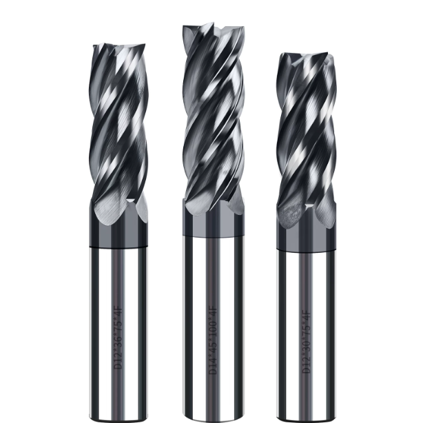
Profiling: Why 4-Flute End Mills for Stainless Steel Offer Superior Rigidity and Surface Finish
When shifting from enclosed slotting to external profile milling or sidewall finishing, the cutting forces change completely. In narrow radial cuts, chip evacuation space is no longer the main constraint. Instead, tool bending rigidity and dynamic stability dictate success. Testing shows that a 4 flutes end mill for stainless steel utilizes its extra cutting edges and higher cross-sectional strength to provide superior vibration control and feed efficiency.
Using tools with fewer flutes and large chip pockets in this scenario often results in subtle elastic deflection. This lateral bending leads to visible chatter marks and wall taper. A 4-flute design distributes cutting loads evenly per revolution and shortens the interval between tooth impacts. This enables machinists to safely increase table feed rates while achieving tight tolerances and exceptional surface finishes.
Controlling Sidewall Chatter and Runout: The Practical Significance of the 4-Flute Tool’s Large Core Diameter for Verticality
When milling tall stainless steel sidewalls, machinists often battle chatter and taper as the cutter reaches full depth. The root cause is excessive tool overhang paired with inadequate core rigidity, which creates high-frequency vibration under load. In our four-flute designs, we expand the core thickness to 58%–65% of the outer diameter, significantly increasing the tool’s resistance against bending forces.
This increased core strength maintains a true vertical cutting path along the entire flute length during lateral passes. It prevents taper defects where parts end up narrower at the top and wider at the bottom. The 4-flute layout also provides more frequent tooth contact, turning heavy, interrupted shocks into a smooth, continuous shear that keeps chatter to an absolute minimum.
Case Study: US Valve Manufacturer Reduces Surface Roughness (Ra) to 0.4μm Using Specialized 4-Flute End Mills for Stainless Steel
Last year, we helped a Texas valve manufacturer refine their machining process on 316L stainless steel flange sealing surfaces. The client needed an ultra-smooth finish of Ra 0.4μm without secondary polishing. They previously used two-flute tools at low feeds, but persistent micro-waviness caused high scrap rates and forced expensive hand-polishing operations.
We introduced specialized 4-flute end mill bits for stainless steel featuring unequal flute spacing. The increased flute count allowed minimal per-tooth chip loads while maintaining fast table feeds, effectively breaking up harmonic resonance. The resulting surface roughness stabilized between Ra 0.35μm and 0.4μm, eliminating manual benchwork and boosting overall production line throughput by 40%.
Integrating Trochoidal/Dynamic Milling: 4-Flute Flat End Mills Achieve High Metal Removal Rates with Large Axial Depths and Small Step-overs
Dynamic milling and trochoidal toolpaths have transformed stainless steel machining, and 4-flute tools are ideal for these strategies. By keeping the radial cut width (Ae) between 5% and 15% of tool diameter, axial depths (Ap) can safely reach 2x to 3x the cutter diameter. The brief contact arc generates minimal cutting heat, allowing the tool to run at high surface speeds.
Under these light radial step-overs, chip clearance is never an issue, allowing carbide flat end mills to leverage their maximum core stiffness. Programmers can push surface footage 1.5 times higher than conventional milling. This utilizes the entire flute length for even wear, reducing spindle loads and delivering significantly higher metal removal rates.

Practical Parameter Chart for Stainless Steel Slotting and Side Milling: Logic for Setting 2-Flute and 4-Flute Carbide Flat End Mills
Many machinists rely on generic speeds and feeds printed on tool packaging, but these numbers rarely account for actual engagement angles. In work-hardening alloys like stainless steel, cutting force distribution varies widely between full-slotting and light profiling. Setting parameters for carbide flat end mills requires understanding the distinct physics of each toolpath.
Slotting demands rapid chip clearing to prevent chip welding under high frictional heat. Conversely, profiling leverages small radial step-overs to maximize cutting speeds and tool rigidity. We recommend building a feed matrix based on true chip thickness. Tailoring parameters to chip gullet capacity and core strength is the best way to extend tool life while maintaining aggressive cycle times.
Reference Comparison of Cutting Speed (Vc) and Feed per Tooth (Fz): 2-Flute Slotting vs. 4-Flute Side Milling
When milling 304 or 316L grades, cutting speed (Vc) and feed per tooth (fz) must match the specific cutting environment. In full-width (1.0xD) slotting with a 2-flute tool, the 180-degree engagement arc traps heat quickly. Keep cutting speeds between 65 and 85 m/min and maintain a solid fz of 0.03 to 0.06 mm/tooth to avoid heat buildup and premature coating failure.
| Tool Type / Machining Operation | Ae | Ap | Vc | fz | Key Process Focus |
| 2 Flutes (Full-Width Slotting) | 1.0 × D (100%) | 0.5 – 0.75 × D | 65 – 85 m/min | 0.03 – 0.06 mm/tooth | Ensure smooth chip evacuation; strictly prevent chip recutting and chip welding (BUE). |
| 4 Flutes (Finishing / Profiling) | 0.1 – 0.2 × D | 1.0 – 1.5 × D | 110 – 140 m/min | 0.02 – 0.04 mm/tooth | Suppress tool deflection and chatter; achieve superior surface finish (Ra). |
| 4 Flutes (Dynamic / Trochoidal Milling) | 0.05 – 0.1 × D | 2.0 – 3.0 × D | 130 – 180 m/min | 0.05 – 0.09 mm/tooth | Leverage chip thinning effect; maximize metal removal rate (MRR) using full flute length. |
When switching to a 4 flutes end mill for stainless steel for side milling at 0.05D–0.15D radial width, the teeth have ample time to cool between cuts. This allows cutting speeds to safely rise to 120–160 m/min. Applying chip-thinning compensation lets you increase table feed rates, completing high-quality finishing passes in significantly shorter cycle times.
Recommendations on Flute Count and Entry Angles for Helical Ramping and Linear Ramping
Never plunge straight down into stainless steel without a pre-drilled pilot hole. The zero-speed dead zone at the tool center will chip instantly under vertical thrust loads. We always advise using helical interpolation or continuous linear ramping. For pocket clearing or opening blind slots, 2-flute cutters are the safest entry choice due to their open center-cutting geometry.
The tool’s flute count directly dictates your maximum ramping angle. When running a 2 flutes end mill for stainless steel, open flute pockets allow ramping angles between 2.0°and 3.5°. If entering with a 4-flute cutter, the thicker core restricts center clearance, requiring you to limit the ramp angle to 0.5°-1.5° to prevent chip packing and center-tooth chipping.
Practical Coolant Experience: The Impact of High-Pressure Oil/Coolant and External Emulsion Spray on the Lifespan of 2-Flute and 4-Flute Stainless Steel Milling Cutters
Coolant delivery method often determines whether a cutter wears out gradually or fractures from thermal shock. When using 2-flute cutters for slotting, the primary role of coolant is mechanical chip evacuation. Standard low-pressure nozzles fail to reach deep slot bottoms, whereas high-pressure through-spindle coolant blasts hot chips away instantly, protecting sharp cutting corners from chip recutting.
During high-speed profiling with stainless steel milling cutters, flutes undergo rapid thermal cycles as they enter and exit the cut. Intermittent coolant splashes cause thermal cracking on the carbide substrate, leading to premature edge chipping. We recommend using continuous flood coolant or high-pressure micro-lubrication (MQL) mist to maintain a stable lubricating film that extends tool life.

Tool Selection from the Manufacturing Perspective: How Professional Carbide End Mill Manufacturers Fine-Tune Cutting Edge Details
When reviewing catalogs, machine shop engineers often focus strictly on outer dimensions, flute length, and coating colors. However, on our 5-axis precision grinding machines, we know that preventing catastrophic failure in tough austenitic alloys comes down to micro-geometry. As experienced carbide end mill manufacturers, we understand that micron-level edge honing and specialized relief angles are what truly extend tool life in stainless steel.
Every micro-feature—from tungsten carbide grain sizing to mirror-polished rake faces—is engineered to reduce work-hardening and prevent BUE. Often, premature tool failure is not caused by operator error, but because standard geometries cannot handle specific cutting forces. Understanding these subtle manufacturing details allows you to assess the real-world limits of your tooling accurately.
Variable Helix and Variable Pitch Designs: Eliminating Resonance in 4-Flute End Mills During Thin-Wall Side Milling
When side-milling thin-walled parts or deep cavities, machinists dread hearing that sharp, high-pitched screech from the machine enclosure. This high-frequency chatter leaves dense vibration marks and causes micro-chipping along the carbide edges. Symmetrical 4-flute designs with equal 90-degree spacing create a constant impact frequency that easily triggers harmonic resonance with the spindle.
When developing a high-performance 4 flutes end mill for stainless steel, we incorporate unequal flute indexing and variable helix angles. This asymmetric layout disrupts cyclic harmonics by staggering tooth impact phases, allowing cutting forces to self-dampen dynamically. In thin-wall profiling, this anti-vibration geometry suppresses chatter and lets the tool maintain high feed rates while producing flat, vertical walls.
Corner Chamfering and Micro-Honing: Key Processes to Prevent Chipping During Initial Stainless Steel Engagement
Many machinists have watched a brand-new cutter fracture at the corner radius before completing its very first entry pass. A sharp, right-angle corner has virtually zero cross-sectional backup. When it hits work-hardened stainless steel, that microscopic point endures extreme compressive shock, instantly causing brittle failure on standard carbide tools.
When producing dedicated end mill bits for stainless steel, we grind a protective micro-chamfer (0.05mm to 0.2mm) or small corner radius at the tip. We then apply controlled edge honing to stabilize the edge radius between 8 and 15 microns. This micro-preparation reinforces the cutting edge, effectively absorbing the mechanical shock of initial engagement and preventing early corner chipping.
When to Commission Custom Flute Geometries from Carbide End Mill Manufacturers for Specialized, Non-Standard Parts
Standard catalog tools easily handle 80% of daily milling jobs in most CNC machine shops. However, complex parts like aerospace valve housings or deep medical components often push standard flute lengths and neck clearances beyond their limits. If adjusting speeds, feeds, and coolant fails to eliminate deflection or chatter, modifying the tool’s core geometry is your best path forward.
Partnering with knowledgeable carbide end mill manufacturers gives you access to custom tooling tailored to your exact part features. This includes adding relieved necks for deep reaches, expanding parabolic chip flutes, or grinding multi-step profiles. Combining multiple operations into a single custom tool cuts cycle times and removes the process risks of pushing standard end mills too far.

Quick Decision-Making Guide (Cheat Sheet) for European and American Machining Shops
Having helped machine shops across North America and Europe solve severe tool breakage, we know operators do not have time to read technical manuals at the control panel. Slotting always requires open chip flutes to manage thermal load, while profiling depends on core thickness to eliminate wall taper. Micro-honing and unequal pitch geometry provide the mechanical foundation for both operations.
To simplify tool selection when working with 304, 316L, or 17-4 PH, we distilled our shop-floor testing into a practical decision framework. Whether programming CAM routines or selecting tools directly at the machine tool rack, you can use these guidelines to match your setup, workholding rigidity, and toolpaths to the safest cutting approach.
30-Second Selection Decision Tree: Logic for Slot Depth-to-Diameter Ratio, Machine Rigidity, Cutting Path, and Flute Count
When setting up a job, take a moment to evaluate your part geometry and toolpaths against these practical operational thresholds:
- For enclosed slots, keyways, or deep pockets (depth > 1.0xD): Run a dedicated 2 flutes end mill for stainless steel with axial step-downs between 0.5D and 0.75D. Maximizing chip clearance prevents swarf packing, edge welding, and catastrophic tool failure.
- For side-wall finishing or dynamic trochoidal roughing (Ae≤0.2D): Switch to a 4-flute flat end mill with an enlarged core. The higher flute count allows higher surface footage, resists lateral deflection, and delivers superior surface finishes.
- For helical ramping without pre-drilled pilot holes: Set your ramp angle between 2° and 3° for 2-flute cutters. If ramping with a 4-flute cutter, keep the entry angle between 1.0° and 1.5° to prevent center-tooth packing.
If Your Machine Spindle Lacks Rigidity or Has Limited RPM, How Should You Choose Between 2-Flute and 4-Flute Cutters?
Shop conditions are rarely ideal, especially on older 40-taper machines or lighter BT30 spindles with maximum speeds capped around 6,000 RPM. On these lighter setups, running full-depth side cuts with 4-flute cutters can trigger heavy low-frequency chatter. Choosing a 2-flute tool reduces the number of cutting edges engaged simultaneously, substantially cutting radial tool pressure on the spindle.
If your machine provides high RPM but limited torque, 4-flute end mill bits for stainless steel running high-speed dynamic toolpaths (small step-over, large axial depth) deliver high metal removal rates without stalling. Every shop deals with different workholding, taper, and machine dynamics. If you are struggling with difficult prints or persistent chatter, share your workpiece prints and cutting parameters with our engineering team to dial in the ideal tooling setup.






