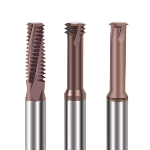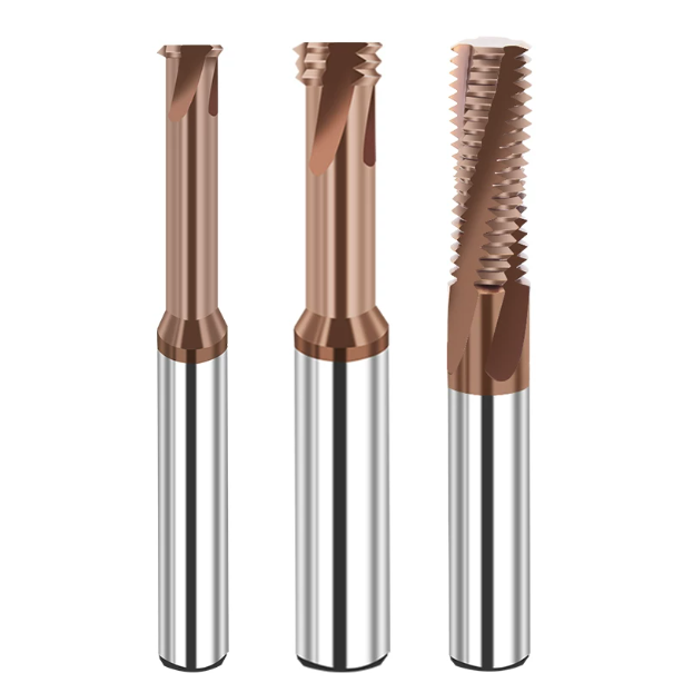
Two months ago, a long-standing mold-making client in Stuttgart reached out to us with an urgent production halt. They were attempting to thread M6 holes into a D2/1.2379 cold-work die core hardened to 62 HRC. They tested premium full-profile cutters from three well-known brands, but every tool failed catastrophically: the best lasted under three holes, while the worst snapped inside the cavity on the first entry.
Over the past 16 years, we have seen this identical failure mode across hundreds of machine shops in North America and Europe. Machinists comfortable with pre-hardened steels often watch their feeds, speeds, and toolpaths fall apart once material hardness passes 60 HRC. When cutting forces surge and work-hardening sets in, standard entry routines cause instant brittle fractures, leaving broken carbide stuck in six-figure mold cavities.
Overcoming these failures requires more than just buying premium thread mills for hardened steel. True reliability comes from a closed-loop machining strategy: pairing sub-micron carbide toughness with heat-resistant coatings, opening up pilot hole tolerances, and switching to high-pressure air blasts. Are you tired of watching your spindle load meter with your hand hovering over the feed hold, waiting for that awful snap?
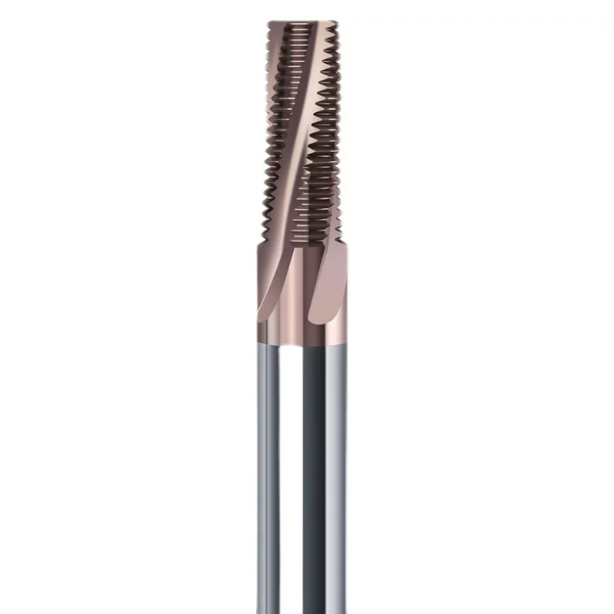
Why Do Thread Mills Frequently Break After Heat Treatment? Three Root Causes We Find on the Shop Floor
Whenever we inspect broken carbide cutters in a customer’s scrap bin, the fracture patterns tell a clear story. Many shops apply the same speeds, feeds, and hole sizing from pre-hardened work to fully quenched parts. They assume a tough cutter alone guarantees success. Once steel passes 60 HRC, its microstructure shifts to a dense matrix of martensite and hard carbides, causing cutting forces to spike dramatically.
At this hardness level, a runout of just two or three microns generates massive side thrust. Drawing from over a decade of troubleshooting stamping dies and casting tooling, we rarely find that the carbide grade itself was defective. Instead, tools are pushed past their mechanical limits by three overlooked process bottlenecks.
Blindly Copying Tap Pilot Hole Sizes: Root Interference and Expansion Rates in 60+ HRC Hardened Steel
We often see machinists grab a standard tapping chart and drill a 5.0 mm hole for a standard M6 thread. In soft steels, that hole size leaves plenty of room. In 60+ HRC tool steel, however, drilling a 5.0 mm hole is a death sentence for the cutter tip. Hardened materials have zero plasticity, meaning the tool cannot displace uncut stock or tolerate minor hole shrinkage from heat-treat stresses.
When programming a metric thread mill, you must target the upper limit of the minor diameter tolerance. For an M6x1.0 thread, we routinely open the pilot hole to 5.10 mm or 5.15 mm while remaining safely inside the 6H tolerance band. This tiny micron-level clearance reduces compressive friction at the crest by nearly 30%, which is our first adjustment whenever an edge chips during initial testing.
A Sharp Rise in Radial Cutting Resistance: Tool Deflection and Brittle Fracture
Machinists often ask us why a cutter runs smoothly in 45 HRC steel but snaps instantly in 62 HRC powder metal. The answer comes down to radial separation force. In 60+ HRC materials, chips no longer shear smoothly; they fracture under extreme compressive stress. This dynamic pushes the cutter away from the cut wall, creating measurable deflection and tool chatter.
This lateral pressure quickly overwhelms a general-purpose thread milling tool. Standard cutters feature deep flutes to maximize chip evacuation, which thins the web and sacrifices core rigidity. When high-hardness materials push back against a slender neck, torsional vibration causes immediate micro-chipping along the cutting edge. We design our hardened-steel tools with a web thickness 20% larger than standard designs to resist that deflection.
The “Hard-on-Hard” Impact of Radial Entry: How Linear Entry Shatters Carbide Edges
Inspecting an operator’s G-code often reveals a straight-line linear approach (G01) straight into the hole wall. While a straight plunge is acceptable in soft steel, it destroys carbide edges in 60+ HRC materials. Ultra-fine grain carbide offers exceptional hot hardness and wear resistance, but it lacks the tensile shock strength needed to survive a direct perpendicular impact against a hardened surface.
To eliminate that shock load, we program an arc-in move of at least 90 degrees, preferably a 180-degree helical roll-in. Even when running premium hrc65 carbide thread mills, a rolling entry is required to gradually scale the chip load from zero to full programmed feed. Easing the cutter into the cut prevents the instantaneous shock that routinely breaks teeth upon initial contact.
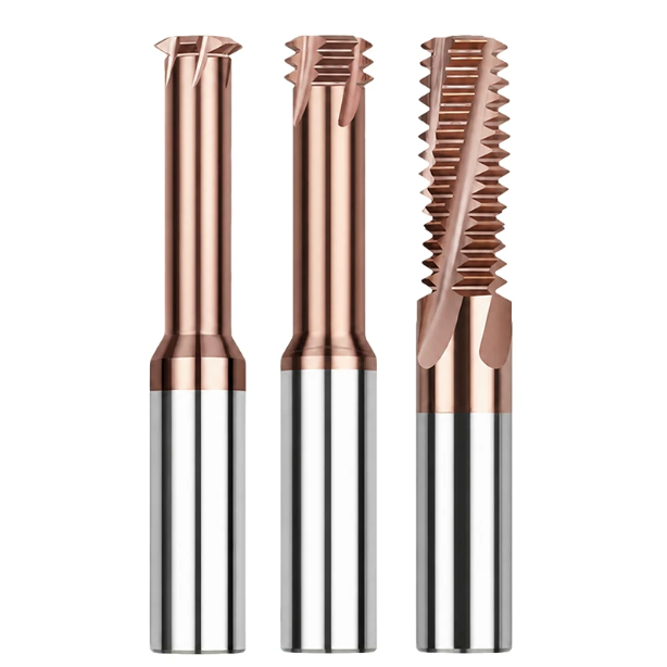
Tackling HRC65–HRC70 Hardened Steel: Redesigning Tool Substrates and Edge Geometries
Many tooling supervisors believe that applying an advanced coating onto a standard end mill geometry will make it cut 65 to 70 HRC steel. Our test logs on five-axis tool grinders prove otherwise. Beyond 65 HRC, the workpiece metal reaches its yield limit, and chip formation transitions into abrasive spalling and friction. Conventional positive rake designs fail within seconds.
Surviving this extreme operating window requires rebuilding the tool geometry from the core up. We eliminate deep, open chip pockets in favor of maximum core cross-sections and reinforced cutting edges. The following design changes are our field-proven solutions developed through years of cutting high-hardness components.
Helix Angle Optimization and Negative Rake Edge Honing for HRC65 Carbide Thread Mills
When machining steels like DC53 or fully hardened D2, a sharp cutting edge creates a dangerous weak point. Sharp, positive edges cannot handle the crushing contact stresses of a martensitic matrix, leading to rapid micro-flaking. We grind our tools with a -2° to -5° radial rake and apply an edge hone radius between 8 and 12 microns. This controlled hone supports the edge, channeling high compressive stresses safely into the carbide body.
Helix angle selection also requires a deliberate trade-off. While steep helix angles evacuate soft chips efficiently, they reduce the core’s resistance to torsional twisting in hard materials. Through real-world testing on stamping die inserts, we found a sweet spot between 15° and 20° for hrc65 carbide thread mills. This lower angle converts radial cutting deflection into axial support, stabilizing the tool and reducing cutting-edge fatigue.
Rigidity Trade-offs for HRC70 Carbide Thread Mills: Why We Advise Against Multi-Flute Full-Profile Designs
When a part reaches 68 to 70 HRC, full-profile thread mills become a liability. Cutting the entire thread depth in a single 360-degree revolution forces every tooth to engage the hardened workpiece at the same time. The resulting radial forces easily bend a slender shank, causing pitch taper errors or snapping the tool off at the shank transition.
For these extreme hardness levels, we advise shops to switch to single-form or short-stack profiles (two to three teeth). While a single-form cutter takes longer to run, it cuts radial contact area by 70% to 80%. This brings cutting resistance back into a range your spindle and toolholder can manage. When running hrc70 carbide thread mills, sacrificing a few seconds of cycle time is the only reliable way to protect expensive workpieces.
Real-World Performance of Nanocomposite Coatings: Preventing Tip Spalling During Dry Cutting
In dry-milling hardened steel, localized friction temperatures at the cutting edge routinely exceed 900°C (1650°F). When customers send us failed tools, we often see the coating peeled off the tip, leaving the raw carbide exposed to thermal wear. This failure is rarely caused by low surface hardness; it stems from thermal stress shearing the coating off its substrate.
To solve this issue, we rely on advanced surface preparation and specialized thin-film coatings. We treat the raw carbide using glow-discharge ion cleaning, apply an adhesive gradient layer, and cap it with a TiAlSiN or AlCr-based nanocomposite coating. This multilayer structure raises thermal oxidation resistance above 1100°C, ensuring friction heat evacuates with the chip rather than destroying your thread milling tool.
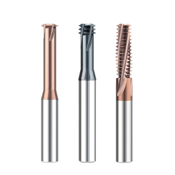
Practical Machining of Hardened Mold Steel: Selecting the Most Fracture-Resistant Thread Mills
Adding ejector pin holes or modifying thread sizes on mold inserts already hardened past 60 HRC is a high-stakes task. Many machinists simply grab any cutter with an adequate flute length off the rack. In hardened die steels, however, zero material yield means that even a minor mismatch in tool geometry will instantly trigger catastrophic tool failure.
Selecting cutters for 60+ HRC substrates requires looking past nominal thread diameter and pitch. You must evaluate the dynamic interaction between cutting resistance, flute overhang, and machine spindle rigidity. In tight spaces where chip evacuation is restricted, choosing the correct type of thread mills engineered specifically for deflection resistance is the only way to protect expensive mold inserts from being scrapped.
Tool Life Comparison: Single-Form vs. Multi-Form Thread Mills for Repairing 60+ HRC Mold Inserts
When modifying a hardened automotive stamping die worth six figures, machinists often reach for full-profile multi-form tools to save cycle time. However, our shop-floor testing reveals that full-profile cutters are exceptionally vulnerable to localized hardness variations. When all teeth engage simultaneously, radial cutting spikes overwhelm the tool web, causing rapid, multi-tooth fracture across the entire array.
For reliable mold repairs, we strongly recommend single-form cutters. Because only a single profile engages the workpiece, cutting resistance drops significantly, allowing smooth interpolation even on machines with moderate servo stiffness. In production testing on hardened H13 die inserts, single-form thread mills for hardened steel extended average tool life from a dozen holes to over one hundred, cutting total tooling and downtime costs by more than 50%.
Vibration-Damping Performance of Short-Overhang Straight-Flute vs. Micro-Helical Flute Thread Mills in Deep Blind Holes
Blind-hole threading in hardened tool steel presents a severe chip evacuation challenge. Operators often select high-helix tools hoping to pull chips upward, but high-helix flutes thin out the tool core. Under heavy cutting pressure, hard chips roll against the back of the tooth, inducing high-frequency chatter that rapidly snaps the cutting tip off at its base.
To maximize rigidity in deep blind holes, short-reach straight-flute tools provide the highest torsional strength, though they restrict chip flow. A micro-helix design (10° to 12°) strikes the ideal practical balance. Choosing this type of thread mills provides just enough axial lift to clear chips while maintaining maximum cross-sectional mass, preventing chatter-induced fractures deep inside the bore.
Deep-Hole Metric Thread Milling: Balancing Neck Rigidity and Chip Evacuation
Machining small internal threads like M3 to M5 in deep, hardened pockets frequently causes tool breakage at the neck transition. Toolmakers often undercut the neck excessively to clear the hole wall. In 60+ HRC tool steel, a slender neck behaves like a torsion spring, twisting and deflecting under load until the brittle carbide fractures.
To prevent deflection without causing wall drag, we engineer our relieved necks with a generous transition radius and tight clearance tolerances. This geometry keeps the neck cross-section as thick as possible while remaining fully clear of the minor diameter. The resulting metric thread mill provides the dynamic bending stiffness required to eliminate thread taper and prevent breakage at reach ratios of 3:1 or 4:1.
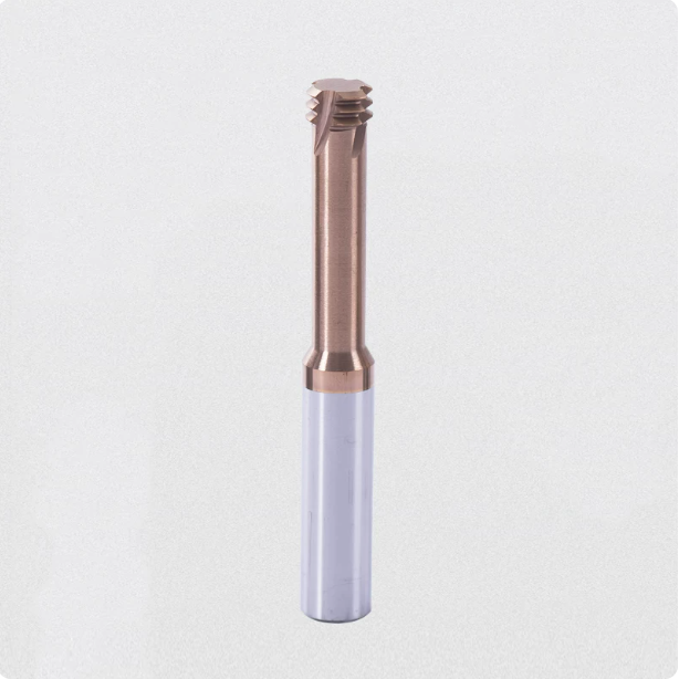
Core Rules for On-Site Programming and Operation to Eliminate Tool Breakage (Shop-Floor Insights)
When carbide breaks in hardened steel, operators usually blame the tool material first. Looking at the G-code, however, often uncovers the real culprit: poorly configured lead-in paths and stepover values. Materials hardened to 60+ HRC cannot yield plastically, meaning any abrupt directional change or feed hesitation delivers a destructive shock wave directly into the cutting edge.
Throughout our years supporting tooling shops across North America and Europe, we have established a strict set of operating guidelines. By dialing in runout tolerances, helical approach arcs, and radial stepovers, you can eliminate edge chipping and push a standard thread milling tool to its full design potential.
180° Arc Entry and Exit (Roll-In): Protecting Carbide Edges from Impact Damage
The most common programming mistake we observe is driving the tool straight into the bore wall using a linear G01 move. In 60+ HRC steels, entering perpendicular to the surface creates an extreme shock load that shatters the carbide cutting edge within milliseconds of contact.
We mandate a 180-degree semicircular helical roll-in and roll-out path in the CAM post-processor. This geometry gradually scales the chip load from absolute zero up to the programmed feed-per-tooth, stabilizing the machine axes before full engagement. Combining this roll-in path with high-rigidity hrc65 carbide thread mills shields the fragile edge and completely eliminates entry chipping.
Layered Milling Depth Planning: Radial Multi-Pass Allowance Allocation and Spring Pass Correction
Attempting to cut full thread depth in a single radial pass in 60+ HRC steel is a guaranteed way to break the cutter. Massive radial push-off forces bend the tool, creating tapered threads that are loose at the top and tight at the bottom. The tool often binds and snaps during retraction.
Instead, we program a three-step radial multi-pass routine: roughing at 60% total depth, semi-finishing at 30%, and finishing at 10%, followed by a zero-radial-feed spring pass. This step-down sequence stabilizes cutting forces during every orbit. It allows hrc70 carbide thread mills to hold strict pitch diameter tolerances without deflection errors.
Coolant Medium Analysis: Why High-Pressure Cold Air Outperforms Cutting Fluid
Flooding the cut with water-soluble coolant is a leading cause of edge chipping in hardened steels. As the tool rotates in and out of the cut, the teeth experience rapid thermal cycling between extreme friction heat and instant liquid quenching. This thermal shock causes micro-cracking across the carbide substrate, leading to premature flaking.
We recommend using dry, 6 to 8 bar high-pressure air blast or minimum quantity lubrication (MQL). Dry air eliminates thermal shock while instantly clearing hard, abrasive chips out of the bore to prevent recutting. Supplying clean, high-velocity air is essential to maximizing the life of thread mills for hardened steel.
Cutting Edge Linear Speed vs. Tool Center Feed: Avoiding the CAM Centerline Overload Trap
Programming a feed rate of 0.05 mm/tooth directly into CAM software can unintentionally overload your tool by 200% to 300%. Machine controllers calculate the feed rate (F) along the tool’s centerline path. In an internal arc, that centerline path travels a much shorter distance than the outer cutting edge, creating an invisible, massive increase in actual chip load.
When running a small-diameter metric thread mill, you must apply an internal feed-rate compensation formula to scale down the controller’s F-value. Calibrating the programmed feed ensures the outer edge maintains the intended chip thickness. This simple adjustment prevents tool overload and keeps cutting forces safely within structural limits.

On-Site Emergency Diagnosis for Quality Failures and Frequent Tool Wear
During high-volume runs of hardened mold cores or aerospace components, the true nightmare is pulling a part off the machine only to find the Go gauge binding at the hole entrance. Machine shops often panic at this stage. Operators instinctively crank up the feed rate or switch to an expensive catalog tool, only to discover that the very next piece fails inspection again.
These recurring defects can almost always be diagnosed directly at the machine tool. Hardened steel provides instantaneous feedback through acoustic pitch, dimensional drift, and hole-wall condition. Mastering this diagnostic logic allows machinists to identify root causes in minutes and restore thread mills for hardened steel to a stable, repeatable tolerance band.
Thread Gauge Anomalies: Correcting “Loose Top, Tight Bottom” Taper Caused by Deflection
When inspecting 62+ HRC threads, a common defect is a Go gauge that turns two threads and jams, while the No-Go gauge wobbles loosely at the mouth. This issue stems from tool deflection under heavy radial cutting pressure. Simply adjusting the global cutter radius compensation (D-value) will scrap the part: the entrance opens up out of spec while the tapered bottom remains too tight.
We correct this taper by combining localized tool offsets with an unforced spring pass. In your NC program, add a secondary finishing orbit with zero radial depth of cut, or increase the offset value by 0.01 to 0.02 mm exclusively at the bottom of the bore. This strategy allows the natural spring-back of hrc65 carbide thread mills to clean up remaining stock, restoring proper cylindricity without scrapping valuable inserts.
Identifying Early Signs of Micro-Chipping: Stopping the Cycle Before Catastrophic Failure
Experienced machinists know that spindle sound provides an earlier warning than digital load monitors. When air-cooling materials over 60 HRC, a healthy carbide cutter produces a continuous, high-frequency hiss during helical interpolation. If that steady pitch is suddenly interrupted by a dull rhythmic tap or a raspy drag, hit the feed hold immediately.
That subtle tonal shift indicates that an individual tooth has suffered micro-chipping. In extreme-hardness steels, that tiny defect rapidly triggers a destructive snowball effect, snapping the cutter shank within two spindle revolutions. Stopping the cycle right away to inspect the rake face allows you to swap the thread milling tool before it fractures inside the hole, saving the mold from costly EDM extraction.
Tool Breakage Caused by Pilot Hole Burr Compression: The Critical Role of Pre-Chamfering
During shop audits, we frequently catch operators scheduling hole chamfering after the threading cycle to save a tool change. In pre-hardened materials, this sequence rarely causes problems. In fully quenched mold steels, however, drill breakout leaves a work-hardened rim with burrs that measure 2 to 3 HRC points harder than the parent metal.
When the cutter enters along its helical path, the fragile tip slams directly into this hardened ridge rather than a prepared surface. This sudden impact chips the rake face before full thread engagement even begins. We always require pre-chamfering the hole to 45° or 60° beyond the major diameter using a rigid tool, ensuring a smooth entry that protects your metric thread mill from premature failure.
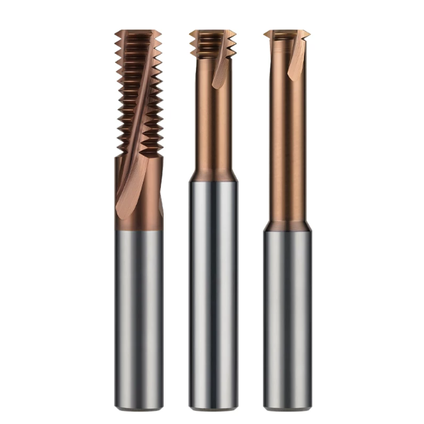
As a Carbide Thread Mill Manufacturer, How We Customize Non-Standard Tools for High Hardness
Process tweaks like hole clearance, arc roll-in paths, and feed compensation all lead toward the same goal: balancing cutting forces against structural limits. When dealing with 60 to 70 HRC steels, off-the-shelf catalog tools only work under textbook conditions. Deep pockets, thin-walled workpieces, and abrasive powder-metal alloys quickly push standard tools past their breaking point.
This performance gap is why our shop focuses heavily on custom engineering for extreme environments. As an established carbide thread mill manufacturer, we know that testing standard tools on expensive dies risks catastrophic failure. Effective customization requires matching machine dynamics, material grain structures, and toolholder runout tolerances to engineer an application-specific solution.
Analyzing Fracture Surface Grains: Material Traceability and Root-Cause Review
When a shop encounters repeated tool breakage, we ask them to send back the broken fragments rather than loading another cutter. A scanning electron microscope reveals what really happened: distinct fatigue beach marks expose toolpath chatter, shear slip planes confirm radial feed overload, and micro-cracks point toward thermal shock from liquid coolant.
Tracing grain behavior at the fracture site enables a specialized carbide thread mill manufacturer to optimize substrate composition. If your tools show premature flaking in cold-work tool steel, check the break: is it a flat brittle fracture or a jagged shear tear? We resolve these structural failures by formulating custom tungsten carbide blanks with tailored sub-micron grain structures (0.2–0.4 µm) and targeted cobalt content to arrest crack propagation.
Custom Profiles and Extended Reach for Global Toolrooms: Direct OEM Engineering Access
Toolrooms running aerospace and automotive dies frequently face tight print tolerances—such as high length-to-diameter ratios, asymmetrical crest radii, or shallow blind-hole clearances. Working through third-party distributors often turns critical feedback like “0.015 mm deflection” into vague complaints about tool life, dragging prototype cycles out for months.
Working directly with our engineering team lets us design tools around your actual spindle rigidity and part CAD geometry. If you are struggling with thread taper or edge breakage in deep 65+ HRC holes, send us your reach requirements and workpiece specs. We will optimize the neck relief, core thickness, and negative-rake hone to build tailored thread mills for hardened steel that perform consistently on your shop floor.