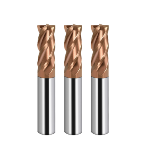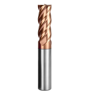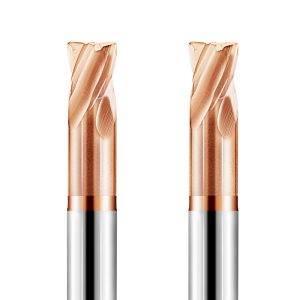
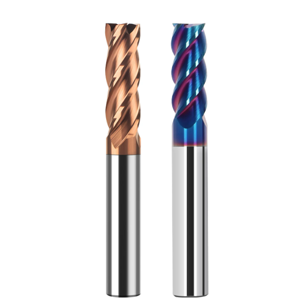
An urgent email from a mold-making client in Bavaria, Germany, highlights a pain point common to many precision machine shops: while finish-machining corners on 1.2379 (AISI D2) stamping die inserts hardened to 65 HRC using a 6mm solid carbide end mill, the tool developed microscopic edge chipping after fewer than two parts. This triggered an immediate spike in cutting force, causing the tool to fracture instantly.
The operator’s instinctive reaction was to dial down the HRC65 end mill feed rate on the control panel to “play it safe.” Paradoxically, this accelerated flank wear and burned the tool. This is not an isolated case. It is a recurring problem we tackle while providing on-site technical support for mold shops across Europe and North America.
When milling materials in the 60 to 65 HRC range, many operators focus strictly on coating temperature limits or spindle speed, ignoring the most critical control variable: the end mill feed rate. Once workpiece hardness approaches tool hardness, feed calculations no longer follow linear rules. If feed drops below the minimum chip thickness, the cutting edge simply rubs and burnishes the hardened surface. Conversely, a slight feed overload shatters the carbide’s brittle cutting edge.
Achieving a balance between wear resistance and chipping resistance requires linking your cutting speed feed rate directly to radial engagement (ae), tool overhang, and cutting-edge preparation. Dialing in HRC65 end mill feed parameters comes down to controlling microscopic negative lands and chip thinning, not copying generic textbook formulas.
Have you ever stood in front of a machining center watching an imported end mill chip within minutes, wondering whether to drop the feed for safety or push it harder to bite through the hardened crust?
Why Do Recommended Values Lead to Tool Failure? Our Empirically Derived Feed Rate Window for HRC 65 End Mills
Catalog cutting tables look great on paper, but they assume ideal conditions. Toolmakers test them on ultra-rigid horizontal machining centers with thick, solid test blocks and zero runout. In real-world mold cavities, you face corner load spikes, slight tool deflection, and uneven stock. In these conditions, catalog data often triggers immediate edge failure.
On the shop floor, the workable end mill feed rate window is narrow and unforgiving. We never treat it as a static number. Instead, we tune the feed rate against radial stepover, tool overhang, and machine rigidity. Keeping spindle load stable and suppressing high-frequency chatter is always more valuable than chasing theoretical metal removal rates.
Establishing Baseline Cutting Speeds and Feed Rates for Common Heat-Treated Materials in Western Workshops
Our team frequently supports shops running cryo-treated AISI D2 (1.2379), powder-metal CPM 1V, and fully hardened H13. Even when all three test at 60–65 HRC, they cut very differently. D2 features coarse, abrasive eutectic carbides that hammer the cutting edge. Powder metals like CPM have a uniform carbide structure, but their dense matrix creates massive shear resistance.
To establish a safe cutting speed feed rate baseline, we generally start with a conservative surface speed of 45 to 75 m/min (150–250 SFM). For high-chromium steels like D2, the feed must be positive enough to shear through hard carbide pockets. For tougher hot-work die steels, we slightly trim surface speed and maintain tooth load so cut chips carry the heat away.
Common Pitfalls: “Burnishing Friction” from Insufficient Feed vs. Micro-chipping from Excessive Feed
The most dangerous instinct on hard steel is dialing the feed override down to 30%. When the feed per tooth drops below the hone radius of the cutting edge, the tool cannot shear material. It simply slides, rubs, and burnishes the hardened surface. This severe friction spikes localized temperatures, work-hardens the workpiece, and rapidly destroys the tool flank.
Push the feed too hard, however, and the impact shock will exceed the transverse rupture strength of the carbide. This causes micro-chipping along the cutting edge. Once micro-chipping starts, cutting forces double within seconds and the tool breaks. When optimizing carbide end mill cutting parameters, listen for a dull thudding sound and check for white, torn edges on the cut floor.
Reference Guidelines for Preventing Tool Breakage: Proven Feed Parameters for Solid Carbide Milling Cutters
To help machine shops skip painful trial and error, we developed baseline numbers based on hundreds of hours of field testing. For a 4-flute solid carbide milling cutter in a shrink-fit or hydraulic chuck with under 3D overhang, target a chip load (fz) of 0.008 to 0.035 mm/tooth (0.0003″–0.0014″ IPT). This provides a reliable safety baseline against premature breakage.
Pair this with a shallow radial depth of cut (ae) capped at 4% to 8% of the cutter diameter. Never use liquid coolant—always use a dry, high-pressure air blast to clear chips and prevent thermal shock cracking. If your setup lacks rigidity, reduce your radial stepover instead of cutting your feed rate, ensuring you never drop below minimum chip thickness.
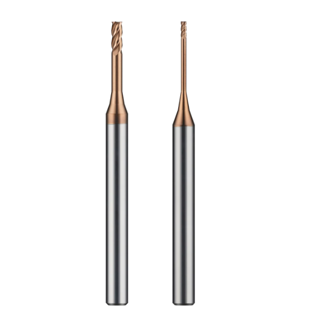
Tool Specifications and Cutting Boundaries: Precisely Setting Carbide End Mill Cutting Parameters
When cutting 60–65 HRC tool steel, evaluating parameters in isolation is a costly mistake. Speeds and feeds depend directly on tool core rigidity, flute geometry, and machine tool dynamics. At this hardness level, a tiny miscalculation in stepover or tooth load creates instant radial deflection. That force focuses directly on the corner radius, causing immediate edge breakdown.
We always define the rigidity boundary of the entire setup before touching feed rates. When troubleshooting jobs for clients across the US and Europe, we first inspect tool overhang, chuck selection, and spindle runout. Dialing in carbide end mill cutting parameters only works when you know the mechanical limits of your toolholder and machine.
Balancing Flute Count and Core Rigidity: Calculating Feed per Tooth (fz) for 4-Flute and Multi-Flute Solid Carbide End Mills
Choosing flute count is a constant trade-off between web thickness and chip room. High-hardness milling generates fine, needle-like chips rather than long curls, so oversized flutes are unnecessary. Standard 4-flute tools offer great chip clearance, but 5- or 6-flute cutters provide a significantly larger core diameter. That extra cross-section resists bending forces and allows higher table feeds.
Do not rely on standard catalog formulas to calculate chip load. With a rigid multi-flute solid carbide milling cutter, you must adjust your target based on the radial engagement angle. Shorter arc contact times mean you should run a lighter chipload per tooth ($f_z$) while increasing programmed table feed. Paired with high-speed toolpaths, shallow multi-flute cuts protect delicate cutting edges far better than heavy 4-flute passes.
Empirical Formulas for Adjusting Milling Feed Rates Based on Overhang and Dynamic Balance
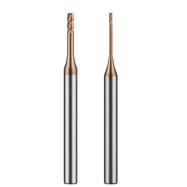
Part interference often forces machinists into long stick-outs reaching 4D to 5D. Tool deflection increases with the cube of overhang length. Once tool extension passes 3D, cutting forces trigger intense high-frequency chatter. In 65 HRC steel, chatter acts like micro-hammering on the edge, stripping coatings and breaking carbide.
For deep-reach cavities, we apply a strict stepped reduction rule. Up to 3D overhang, run baseline speeds and feeds. At 4D, reduce your milling feed rate by 25% to 35% and program smooth arc entries. Past 5D, switch to heavy-metal or carbide-shank extensions. Suppressing resonant vibration becomes your top priority, even if you must lower surface footage to avoid chatter frequencies.
Differences in Feed Parameters for HRC65 End Mills: Trochoidal/High-Feed Milling vs. Full-Depth Side Milling
Machinists often bounce between full-depth side milling and dynamic trochoidal roughing. Both paths create completely different thermal and mechanical stresses on the tool edge. Full-depth side milling uses a tiny radial engagement (ae), producing severe chip thinning. If you do not compensate with a higher feed per tooth, the flute will rub instead of shearing.
High-feed and dynamic peel paths use small stepovers and aggressive linear feeds, but the radial engagement angle changes continuously. When tuning HRC65 end mill feed parameters, we focus on corner transitions and cutter engagement arcs. Keeping cutting forces smooth and predictable as the tool engages hard steel prevents sudden shock breakage.
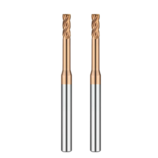
On-Site Machine Tuning for Mold Machining: Practical Application of Carbide End Mill Feeds for Hardened Steel
Real mold cavities expose the limits of baseline speeds and feeds. In our consulting work, over 80% of edge chipping happens during sudden geometry changes—internal corners, pocket entries, and slotting. Once hardened steel hits 60+ HRC, any spike in tool pressure immediately causes brittle failure.
Successful setups require dynamic feed adjustments across the toolpath. Never run a single, flat feed rate throughout a complex hardened cavity. Use adaptive toolpaths, corner deceleration, and radius blending to even out cutting loads. Dialing in your carbide end mill feed for hardened steel across tough features keeps cutters running for hours without chipping.
Deceleration Strategies and Corner Feed Compensation for Clearing Deep Cavities in Plastic and Die-Casting Molds
Internal corners cause the highest failure rates in precision die work. When a tool transitions from a straight wall into a sharp 90-degree corner, the tool engagement angle jumps from 15 degrees to over 90 degrees. This sudden surge spikes chip load. Without look-ahead deceleration, the spindle jolts and the tool corner snaps instantly.
We solve this by programming stepped deceleration zones in the CAM software or with on-machine look-ahead. Approaching a corner, reduce the mold steel milling feed rate by 30% to 50% roughly half a cutter diameter before the corner. Adding corner fillets instead of sharp corners eliminates shock spikes, trading seconds in cycle time for guaranteed process reliability.
Entry Strategies for 60–65 HRC Mold Steel in Closed Cavities: Ramping and Helical Interpolation
Vertical plunging into 65 HRC steel is a guaranteed way to destroy a cutter. The surface footage at the tool center is near zero, and there is nowhere for chips to escape. When pocketing or slotting enclosed features, we require linear ramping or helical interpolation as the only acceptable entry methods.
Match your ramp angle directly to your feed rate. For 65 HRC steel, keep ramp angles between 0.5 and 1.5 degrees, rarely exceeding 2 degrees. During helical entry, set your HRC65 end mill feed to roughly 60% of your linear side-milling rate. Keep the helical bore diameter between 1.2x and 1.6x the tool diameter to give chips an open exit path.
Assessing Thermal Fatigue in Wear-Resistant Coatings Under Extreme Feed-Friction Conditions
Modern coatings like AlTiN, AlCrN, and silicon nanocomposites act as critical heat shields on hardened steel. But feeding too slowly generates excessive friction, driving cutting zone temperatures past 900°C. Repeated thermal cycling between cuts causes micro-cracking due to mismatched thermal expansion rates, leading to severe coating flaking.
Inspect flank wear under a pocket microscope. If you see discoloration rings and flaked coating edges, friction heat is breaking down the bond layer. Avoid flood coolant, which causes rapid thermal shock and fractures carbide. Instead, run dry with a strong high-pressure air blast or MQL, and maintain a positive HRC65 end mill feed so the chips evacuate the heat.
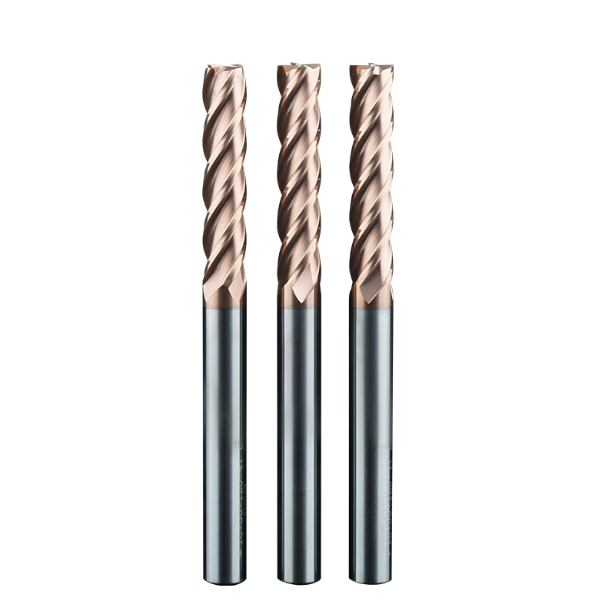
Troubleshooting on the Shop Floor: Deducing End Mill Feed Rate Settings from Chip Morphology and Wear Patterns
Without dynamometers on the shop floor, metal chips on the machine enclosure and wear scars on the tool flank serve as your best diagnostics. Across European and North American facilities, we often solve erratic edge chipping in minutes simply by pulling the toolholder and reading the flutes. At 65 HRC, abnormal chip evacuation is an immediate warning signal that tool failure is imminent.
Learning to reverse-engineer your cut from machining debris prevents unnecessary program rewrites. Inspecting chip geometry alongside flank flaking tells you immediately whether your end mill feed rate is overloading the carbide substrate with shear force or rubbing the work-hardened surface due to insufficient chip load.
Observing Chip Color (Deep Blue to Dark Red) and Curl: A Quick On-Site Method to Determine if the Milling Feed Rate is Excessive or Insufficient
In dry-milling hardened tool steel, the chip must carry away the cutting heat. Look for uniform, tightly curled needle chips or miniature “C” shapes with an even dark-blue temper color. This color proves the shear zone reached the ideal temperature to soften the matrix while your milling feed rate efficiently evacuated the heat.
If chips look pale yellow, silvery, or powdery, your feed is far too light. The cutting edge is burnishing the steel, and the tool flank will rapidly overheat. If chips appear dark red, black, or have ragged, torn edges, drop your table feed immediately. Heavy chip loads create severe shear spikes that break delicate carbide tips.
A “Stopgap” Strategy for Adjusting Carbide End Mill Feed Rates When Machining Hardened Steel with Limited Tooling Rigidity
We often see shops run 60–65 HRC workpieces on standard BT40 or CAT40 machines with long gauge lengths to clear fixtures. Pushing catalog depths of cut on these setups causes chatter and deflection at every shoulder. In low-rigidity environments, standard speeds and feeds quickly lead to broken cutters.
If you face poor rigidity, switch to a lighter radial approach. Reduce your radial depth of cut (ae) and fine-tune your carbide end mill feed for hardened steel by dropping chipload per tooth while raising spindle speed. Material comes off in rapid, low-force passes, preserving tool life and part dimensions when you cannot switch to a stiffer spindle.
Practical Checklist for Optimizing Feed Rates for HRC65 End Mills: Balancing Mold Surface Roughness (Ra < 0.4) with Tool Life
Hitting a mirror finish below Ra 0.4 while keeping cutters alive across long cycles requires disciplined pre-flight checks. High-grade surface finishes depend entirely on chatter-free tool contact rather than theoretical cusp height alone. Deflection or runout ruins surface finishes instantly on hard steel.
If you struggle with finish quality or inconsistent tool life, verify that runout stays under 0.003 mm (0.0001″), keep overhang under 3D, and program stepped corner deceleration. Once you close these physical loops, your calibrated HRC65 end mill feed rate will maintain predictable, mirror-grade cavity walls across 30-plus hours of runtime.
Every setup behaves differently. If you are cutting difficult tool steels like CPM or Vanadis, or fighting long stick-outs on CAT40 spindles, share your setup details with us. We are always glad to compare notes with fellow machinists and dial in a working cutting strategy.