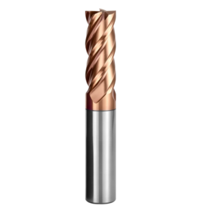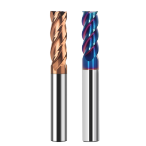
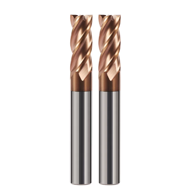
Last month, at a mold facility in Stuttgart, a sharp, piercing screech erupted the instant the spindle hit 8,500 RPM.
The workpiece was a through-hardened powder-metallurgy insert measuring HRC 64–65. The shop was running a standard 4-flute carbide end mill with equal flute spacing. Less than two minutes into the cut, the spindle load spiked violently. We retracted the tool and cleaned off the cutting oil. The cutting edge had broken into micro-chipped notches, and the sidewall showed severe, washboard-like chatter marks that scrapped the part immediately.
Over 16 years of troubleshooting cuts across Europe and North America, we have seen this failure mode countless times. The immediate reaction is usually to drop the feed rate, drop the RPM, or choke up on the stick-out. Yet the real issue rarely stems from machine rigidity or coating wear. The true bottleneck is standard solid carbide end mill geometry.
Milling steels over HRC 60 generates extreme cutting resistance and severe thermal concentration due to minimal plastic deformation. With symmetrical, equal-flute spacing, each tooth engages the workpiece at an identical time interval. This repetitive impact locks the cutting-force frequency directly onto the natural frequencies of the tool holder, spindle, and workpiece assembly.
This creates destructive regenerative chatter, ruining micro-grain carbide edges in seconds and cutting tool life drastically. For deep cavities and high-hardness tooling, we rely on HRC65 end mill unequal flute spacing to solve this. By breaking the symmetry of the tooth angles, we force a continuous phase shift in cutting forces that disperses harmonic energy at the source.
If you machine parts over HRC 60 and cannot eliminate sidewall chatter marks despite constant parameter tweaks, look closely at your tool setup. Could those symmetrical flutes be steering your cutting forces directly into a resonance trap?

Why Equal-Flute Cutters Chip in Hardened Steel: The Real Cutting Forces We See On-Site
Whenever we visit a plant to troubleshoot edge chipping in hardened die steels, seeing a 90° symmetrical cutter tells the whole story. Equal spacing balances chip loads cleanly in mild steels, but it acts as a trap in materials that resist plastic shear. At high hardness, each tooth impact behaves like an unyielding mechanical collision. Identical engagement intervals create undamped, synchronized force spikes across the contact zone.
Using dynamometers to log dynamic cutting forces, we consistently see equal-flute cutters generate clean periodic sine waves in hardened steel. Any micro-shift in chip clearing or core hardness triggers self-excited regenerative chatter instantly. The carbide edge stops shearing smoothly and absorbs rapid micro-impacts far beyond programmed feed limits. This dynamic load quickly shatters the edge integrity of an unequal flute end mill hardened steel setup’s brittle carbide counterpart.
Harmonic Superposition: The Fatal Flaw of Standard 4 Flute Carbide End Mill Cutters in Deep Side Milling
When finish-milling deep vertical walls, machinists often reach for a standard 4 flute carbide end mill to secure adequate chip room and core strength. However, finishing radial cuts (ae) typically engage only 5% to 10% of the tool diameter. That means only one tooth cuts at any single microsecond. With 90° intervals, mechanical shock waves synchronize precisely at four times your spindle rotational frequency.
This setup creates a severe harmonic trap: waviness left by one tooth directly phases into the cut of the following tooth. During a trial in Switzerland on a 4mm-thick hardened rib, shifting spindle speed by merely 50 RPM doubled our peak lateral forces. Standard BT40 holders or basic shrink-fit tooling cannot absorb this load, because the periodic force spikes originate right at the edge-wall interface.
Force Spikes and Surface Collapse: What Happens When an End Mill for Milling HRC62 Hardened Steel Hits Resonance
When running an end mill for milling HRC62 hardened steel on contour passes, surface quality often drops off a cliff. The wall might hold a clean Ra 0.4 finish for 20 minutes before suddenly turning white with severe chatter marks. Many operators assume the coating wore out. Yet stereomicroscopes usually reveal minimal flank wear; instead, resonance has chipped away the edge honing, leaving micro-serrations.
Steels like cold-work D2 or DC53 at HRC 62 are abrasive, brittle, and unforgiving of depth variations. Once chatter sets in, actual chip thickness swings wildly between near-zero rubbing and severe overload. Rubbing work-hardens the surface and spikes friction heat, while the subsequent overload snaps the honed edge. Surface finish does not degrade gradually—it crashes abruptly once harmonic vibration peaks cross the fracture threshold.

Combining Unequal Flute Spacing with Variable Helix Angles: Practical Vibration-Damping Dynamics in Solid Carbide End Mill Geometry
When milling hardened mold steels, a piercing squeal often prompts machinists to simply drop the spindle speed. That is merely a temporary compromise. Real vibration damping starts at the source with dynamic decoupling in solid carbide end mill geometry. While grinding profiles on five-axis CNC tool grinders, we observed that shifting flute spacing alone still allows localized resonance at specific axial depths (ap). True damping requires combining unequal pitch with variable helix angles—such as an alternating 35°/38° layout—to ensure continuous, three-dimensional contact changes along the workpiece.
This geometry prevents shearing forces from forming a repeatable excitation pattern. As the cutter rotates at high RPM, entry angles and exit delays shift continuously down the flute length. This breaks the energy feedback loop needed to sustain regenerative chatter. To an engineer, this is not just a clever design tweak. It is a calculated compromise balancing beam deflection, lateral cutting resistance, and open chip room.
Cutting-Phase Misalignment and Resonance-Disruption Mechanisms in Hardened Steel Machining with Unequal Flute End Mills
When troubleshooting hardened gear dies on-site, we track tooth engagement using high-speed dynamic signal sensors. Running an unequal flute end mill hardened steel setup relies on intentionally asymmetrical indexing, such as an 88°-92°-88°-92° or 87°-93°-89°-91° pattern. This few-degree offset creates a microsecond timing gap between consecutive tooth passes. It forces incoming cutting edges to miss the peak ripples left on the surface by the previous tooth.
Think of it as destructive wave interference. Before micro-vibrations can amplify into full harmonic chatter, the next tooth engages out of phase and cuts the wave off. Individual flutes absorb slight variations in dynamic chip load, but modern micro-grain carbide handles these elastic strains easily. That small load variation is a minor price to pay for suppressing destructive chatter entirely.
Balancing Core Thickness and Flute Design: Preventing Tool Binding and Fracture During Deep-Depth-of-Cut Milling
Pushing axial depths to 1.5D or 2D during deep-wall finishing introduces a tough design trade-off in end mill flute geometry. To counter severe radial pushback in HRC65 steel, engineers often beef up the web to 62%–68% of the tool diameter. However, every point gained in core thickness pinches the flute gullet. Choked chip clearance traps fine debris, quickly causing thermal buildup, tool binding, and sudden breakage.
At a North American client’s shop, we investigated a catastrophic failure during deep-pocket milling with long tool stick-out. The issue was not vibration, but a swollen web lacking flute polishing and eccentric relief. Red-hot micro-chips welded into the gullet bottom, wedging the tool solid. In steels over HRC62, we favor an involute flute profile with polished gash pockets. This provides rigid web backing while leaving clear escape paths for chips under heavy axial loads.
Field Testing of Variable Pitch Designs: Force Distribution at the Tool Tip Under Dynamic Radial Runout
Many machinists worry that the uneven tooth spacing of a variable pitch end mill overloads individual flutes and accelerates corner breakdown. We put this to the test on a vertical machining center using precision shrink-fit holders. With total indicator reading (TIR) held under 3 microns (≤ 0.003 mm), the cutting force imbalance between flutes measured only 6% to 9%. That is far lower than the single-tooth overload caused by typical spindle runout on standard equal-pitch cutters.
At the cutting edge, unequal spacing smooths out sharp force spikes. By eliminating harmonic amplification, each tooth experiences a steady, quasi-static normal load instead of repetitive hammer blows. The wear land along the flank develops evenly and predictably. However, this demands strict toolholder hygiene: if your tool assembly runout exceeds 0.008 mm, it wipes out the damping benefits of variable pitch and forces single-tooth chipping.
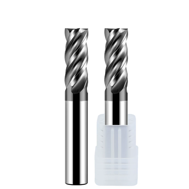
Matching Flute Count with Material Hardness: Selecting Between 4-Flute and 6-Flute Carbide End Mills
Many shops assume that higher flute counts are always better for hard steels, while others run a 4-flute cutter for every job. Based on our field trials across Europe and the US, choosing between a 4 flute carbide end mill and a 6 flute carbide end mill comes down to chip room versus structural bending stiffness. Near HRC65, shearing gives way to high-pressure scraping and micro-fracture. Material removal rates take a back seat to tool stability, and flute count dictates both cutting forces and impact frequencies.
Plunging a multi-flute tool into deep cavities often causes chipping from recutting chips trapped in narrow flutes, not from cutting forces. Conversely, sticking to four flutes on shallow, wide contour cuts leaves significant spindle throughput on the table. When helping shops choose between 4-flute and 6-flute options, we look at the radial step-over (ae) relative to tool diameter first. If chips cannot evacuate freely, flute count means nothing.
Deep Cavity and Slotting: Balancing Chip-Evacuation Capacity and Rigidity with 4-Flute Unequal-Pitch End Mills
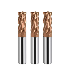
When cutting depths exceed 2D or during semi-enclosed slotting, we routinely set up clients with a 4-flute unequal pitch end mill. Slotting in HRC60+ materials creates a 180° engagement wrap with almost zero room for chip escape. A 4-flute layout leaves open gullets that eject brittle, purple-blued micro-chips before they can pack into the cut, grind against the workpiece, and snap the tool.
The unequal flute geometry solves the chatter problems that plague standard 4-flute cutters under heavy slotting engagement. During a die-machining trial in Italy, we held the core at 60% of diameter while dialing in variable pitch spacing. The tool cleared chips cleanly while completely eliminating low-frequency thumping on heavy cuts. For slotting and corner pocketing, it remains our most reliable compromise between chip clearance and tool deflection.
Precision Milling and High-Speed Dynamic Milling: Chatter Suppression with 6-Flute Carbide End Mills at Ultra-Low Feed-per-Tooth
For finishing tall sidewalls or running high-speed trochoidal toolpaths, our choice shifts to a 6 flute carbide end mill. Multi-flute designs feature thick cores—often 68% to 72% of diameter—giving them the beam strength needed to fight radial deflection. Six flutes also sustain healthy table feeds (Vf) while keeping chip loads (fz) down to an ultra-fine 0.008 to 0.01 mm per tooth.
In hardened steels, tool deflection at tooth entry triggers instantaneous chatter. A 6-flute variable-index cutter divides the contact arc into short, rapid pulses, spreading cutting resistance smoothly across spindle bearings. As long as holder runout is tightly controlled and radial engagement (ae) stays below 5%, a 6-flute geometry achieves clean sidewall finishes that 4-flute cutters simply cannot match.
The Critical Hardness Threshold: Adjusting Negative T-lands and Edge Honing for HRC 58–62 vs HRC 65 Materials
Applying edge preps meant for HRC58 mold steel to an HRC65 part is a sure recipe for chipped edges within minutes. We treat HRC62 as a strict geometric boundary. Between HRC58 and HRC62, steels retain enough yield ductility to reward a relatively sharp edge. We grind these with a light negative T-land of -5° to -8° (0.02–0.03 mm wide) and an 8–12 micron hone to keep cutting resistance low.
At HRC65, machining behaves like abrasive micro-grinding. Delicate edges shatter upon impact with hardened carbide precipitates. For an HRC65 end mill for hardened steel milling, we grind a robust -10° to -15° negative chamfer spanning 0.04 to 0.05 mm, backed by a dual-stage abrasive brush hone. The slightly higher radial force is an intentional trade-off: a rounded, reinforced edge is the only geometry that cuts for hours without micro-chipping.

Real-World Case Study from Western Workshops: Parameter Tuning and Clamping Protocols for HRC65 End Mills in Hardened Steel Milling
Applying variable-pitch geometry and micro-honed edges on the shop floor tests your clamping setup immediately. In many facilities, operators swap cutters without checking holder and spindle interface wear. Milling materials at HRC 64–65 generates massive cutting forces compared to carbon steels. Runout of just a few microns gets amplified by the hardened grain boundaries. That is why dynamic balance and runout verification are mandatory when running an HRC65 end mill for hardened steel milling.
If you are currently running standard ER collet chucks or set-screw side-lock holders, pause and check total indicator reading (TIR) at the tool tip. Our tests show that runout exceeding 0.005 mm destroys the chatter-suppression benefits of variable pitch geometry. For deep cuts in hard steel, switch to precision shrink-fit or hydraulic chucks. Always verify that spindle-to-taper contact exceeds 85% to support dynamic, asymmetrical cutting loads.
Machining Die-Casting Inserts: How Unequal-Pitch End Mills Eliminate Tool-Pass Marks and High-Frequency Chatter on Deep Side Walls
At an automotive mold shop in Detroit, we helped troubleshoot 45 mm deep sidewalls on 1.2343 ESR inserts hardened to HRC 63–65. The shop was running equal-pitch cutters in constant-Z steps. The cut generated high-pitched spindle squeal and left pronounced step-down witness marks across the walls. Bench hands were spending hours hand-stoning each cavity to salvage the finish.
We replaced the tools with a 4-flute unequal pitch end mill featuring polished chip gullets. The broken tooth timing stopped lateral forces from synchronizing into standing acoustic waves. The piercing chatter vanished within thirty seconds. Sidewall roughness dropped to a consistent Ra 0.25, while tool life doubled from two to four inserts per tool without edge breakdown.
A Practical Pitfall with Overhang Ratios Exceeding 3.5D: Re-evaluating Tool-Holder Rigidity and Cutting Speed (Vc) with Variable-Pitch Geometry
When stick-out stretches past 3.5D or 4D, machinists instinctively drop the feed per tooth (fz). This is a costly trap in hardened steels. When feed drops below the edge hone radius, the tool stops shearing and starts rubbing. This friction causes rapid thermal spiking that anneals the carbide tip in seconds without damping vibration.
If you are dealing with long reach, keep chip thickness healthy by maintaining fz at 0.012 to 0.015 mm/z. Instead, dial back surface speed (Vc) from 65 m/min to 45–50 m/min to drop out of the machine’s harmonic zone while letting the variable pitch end mill break the chatter. When possible, run a tapered-neck tool body rather than chasing feed rate overrides on the controller.
Every shop faces distinct variables: spindle taper wear, machine age, toolholder balance, and heat-treat lot variations. If you are struggling with poor sidewall finish, witness marks, or stubborn chatter in hardened steel, send over your cut data, workpiece material, or part drawings. We can look at your parameters, tool geometry, and toolpaths together as engineers.