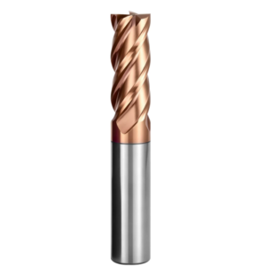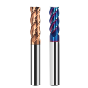
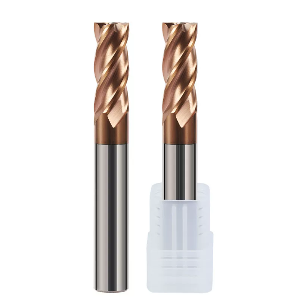
Last month, our team assisted an automotive mold client in Stuttgart with on-site troubleshooting. They were hard-milling heat-treated 1.2379 tool steel (D2 cold-work steel at 64–65 HRC) on a 5-axis machining center. After cycling through three batches of imported cutters, micro-spalling appeared along the sidewall within eight minutes. This quickly escalated into severe chipping, causing spindle load to spike by nearly 40%.
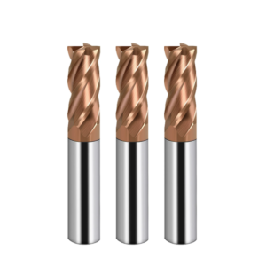
Machinists often react by dropping feed rates, lowering cutting speed, or swapping to harder coatings. In our sixteen years of tooling manufacturing and shop-floor support, this approach only treats symptoms. Once hardness exceeds 60 HRC, positive or weak negative cutters cannot survive the impact of a hardened martensitic matrix. Handling these extreme cuts demands dedicated carbide end mills for hardened steel with sufficient backing carbide.
Under an electron microscope, the failed edges showed pure high-pressure shear fatigue. Many shops focus heavily on sub-micron carbide grades and AlTiN/Si nano-coatings while ignoring the most critical safeguard: the end mill rake angle. Hardened milling is not smooth slicing; the cutting edge undergoes severe plastic deformation and high-temperature compression.
Optimizing tool geometry redirects cutting force vectors back into the tool body rather than across the fragile edge. Should axial and radial negative rakes sit at -10° or -15°? How do negative lands (T-lands) and edge honings work together to distribute shear stress without causing thermal runaways? If your tool runout is under 0.003 mm yet tool life hits a wall at ten minutes, can your current cutting geometry truly survive 65 HRC material?
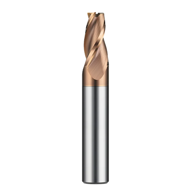
Why Standard Tools Fail on Hardened Steel: The Reality of Edge Chipping Observed on the Shop Floor
During shop-floor audits across Europe and the US, we often see operators trying to cut hardened die steel with standard general-purpose end mills. Many believe that cutting feed rates in half and setting depth of cut to 0.05 mm will let a standard tool squeak through. However, spindle vibration spikes and edge fractures tell the real story. Once hardness crosses 60 HRC, the physics of chip formation changes entirely.
In dense quenched martensite, chips do not form via continuous shear slip. Instead, material is torn and extruded ahead of the edge under extreme hydrostatic pressure. Standard flute shapes and clearance angles are built for ductile materials. Under extreme mechanical stress, heat concentrates along a microscopic contact band, causing tools that lack dedicated HRC65 end mill geometry to micro-crack and chip instantly.
Addressing Cutting Stress Characteristics of 65 HRC Workpieces: Why Specialized Carbide End Mills for Hardened Steel Are Essential
During a force-monitoring trial on 64–65.5 HRC cold-work die steel, our cutting dynamometer recorded an immediate spike in normal thrust force. Normal force reached 2.5 to 3 times the tangential cutting force. The primary load is not smooth shearing, but massive perpendicular compression against the rake face, accompanied by instantaneous contact temperatures exceeding 800°C.
Standard tungsten carbide with 0.6–0.8 μm grain structures develops rapid thermal fatigue cracking under this cyclic pounding. A dedicated carbide end mill for hardened steel relies on sub-micron grain substrates with cobalt content restricted to 8%–10%. This formulation does not just raise bulk hardness; it delivers the compressive yield strength needed to prevent plastic deformation under extreme shock.
Micro-chipping Induced by Positive Rake Angles: Insufficient Cutting Edge Support Strength Revealed by a Case Study from a German Mold Shop
A failure analysis we conducted for an automotive mold shop in Stuttgart illustrates this issue clearly. Machining hardened deep cavities, the programmer chose a general-purpose end mill with a +3° nominal rake angle to reduce cutting resistance. Within five minutes, fish-scale tear marks covered the cavity sidewalls. High-magnification inspection revealed no standard flank wear, but rather continuous, serrated micro-chipping.
A positive rake angle eases chip flow and cuts spindle loads, but it thins the wedge angle supporting the edge. Interrupted cuts in 65 HRC steel convert this thinned tip into a cantilever beam under heavy cyclic bending. Because tungsten carbide has far lower tensile strength than compressive strength, micro-bending fatigue causes brittle edge fracture. A positive end mill rake angle trades away structural survival for temporary cutting ease.
The Trade-off Between Tool Body Rigidity and Chip Evacuation: Underlying Logic for Optimizing Hardened Steel Milling Tool Geometry
Tool manufacturing always involves a trade-off between web core thickness and chip pocket clearance. Some machinists assume that boosting core thickness to 65% or 70% of the cutter diameter solves every chatter issue. However, 65 HRC chips form as fine, abrasive dust or tiny flakes. If the flute gullet is over-constricted, these hot, hard particles pack into the flutes, causing secondary cutting, thermal spikes, and edge blowout.
Our grinding shop balances core mass against chip space based on overhang ratios. At overhangs over 3:1, we reinforce core thickness and apply eccentric relief lands to suppress chatter and deflection. For short-reach high-speed finishing, we maintain generous flute curvature alongside variable helix spacing to break harmonic resonance. Optimizing hardened steel milling tool geometry is always a calculated compromise between fracture resistance, dynamic stiffness, and smooth chip evacuation.
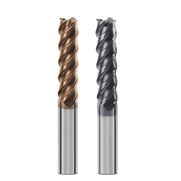
The Key to Rake Angle Design: Balancing Critical Parameters for Hardened Steel End Mills
In precision tool grinding, the rake angle acts as the helm directing cutting forces. When clients return fractured tools, radial shell patterns on the edge usually point to weak compressive reserves behind the tip. At 65 HRC, workpiece fracture toughness drops drastically. If the wedge angle falls below a safe threshold, the edge takes the full brunt of peak shear loads.
We use negative geometry to convert destructive tensile stresses into compressive loads that tungsten carbide handles best. Increasing rake angles to lighten spindle load causes catastrophic edge failure within the first two passes. Conversely, an overly blunt edge triggers severe friction and heat extrusion. Mastering the end mill rake angle is essential for high-volume, predictable machining.
Selection Criteria for the Negative Rake Range: Vibration-Dampening Performance of -10° to -15° Rake Angles in Interrupted Cutting
During an on-site audit for a North American stamping die shop, we faced severe interrupted cutting around ejector holes and step drops. Standard -5° cutters caused frequent spindle alarms, and edge micro-chipping hit 80% within fifteen minutes. We ground a test batch with a -12° rake angle. The change smoothed out harmonic spikes and doubled tool life immediately.
Dynamic force data shows that a -10° to -15° end mill rake angle pushes the shear initiation point deeper onto the rake face. This shift moves primary impact away from the delicate tip into solid backing carbide. However, run a -15° angle only on high-rigidity spindles. On weaker setups, an aggressive negative angle can induce low-frequency chatter instead of damping it.
Dual Negative Rake Angle Configuration (Radial and Axial): Balancing Extreme Impact Resistance with Sidewall Finish
Finishing hardened sidewalls often forces an unwelcome compromise. A single negative rake resists chipping, but sidewalls frequently show chatter lines and stall near Ra 0.8 μm. To solve this, we grind compound radial and axial negative rakes on our 5-axis CNC grinders. This compound geometry redirects the 3D chip flow vector, stopping abrasive chips from rubbing against finished walls.
The axial negative rake channels cutting forces toward the spindle nose, utilizing high axial thrust stiffness to resist lateral deflection. Meanwhile, a moderate radial angle protects the peripheral cutting edge. Tuning this compound end mill cutting geometry balances edge strength with clean shearing, avoiding push-rub burnishing while holding mirror finishes on precision mold inserts.
Avoiding “Push-Rub Heat” and Premature Wear: Fine-Tuning the Critical Rake Angle Window for HRC65 End Mills
Taking negative rake angles to extremes creates another common failure mode. In smaller shops, operators sometimes grind excessive negative rakes hoping to eliminate chipping entirely. The cutter loses its ability to slice into the material, turning cutting into dry, high-friction pushing. Chips come out dark purple, and frictional heat quickly destroys the nano-coating.
We grind our tools within a tightly controlled parameter window. The targeted HRC65 end mill rake angle must generate concentrated shear stress right at entry. This localized heat softens the hardened steel shear zone without overheating the carbide substrate. Exceeding this boundary accelerates abrasive flank wear into catastrophic thermal breakdown.
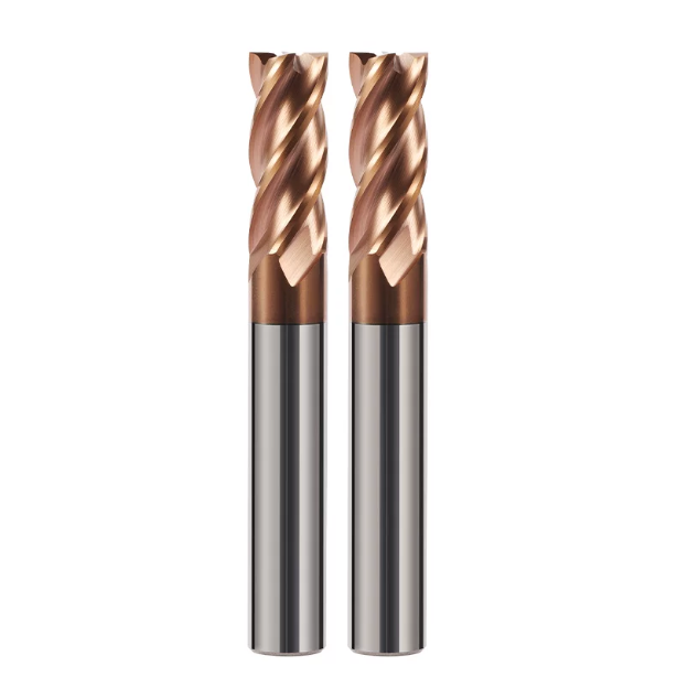
Beyond a Single Angle: Engineering HRC65 End Mill Geometry to Withstand High-Pressure Impact
Many machinists focus solely on rake angles, assuming a steeper negative face makes a tool indestructible. Our shop experience proves that adjusting rake angles alone leaves you vulnerable. At 65 HRC, cutting loads create complex, alternating 3D forces. Without a matching structural foundation behind the edge, peak stresses will find the weakest link and fracture the cutter.
Tool performance depends on the combined torsional stiffness of the entire cutter body. Micro-edge prep, flute curvature, core mass, and helix angles form an integrated support network. A razor-sharp edge breaks instantly without a micro-chamfer, while a weak core causes lateral deflection and chatter. Only a holistic HRC65 end mill geometry survives heavy cyclic shock in hardened tool steels.
Micro-Honing and Negative T-Lands: Passivation Parameters That Protect Tool Integrity Better Than Rake Angle Alone
We diagnosed an aerospace mold maker in Germany suffering micro-chipping within the first three minutes of cutting. White-light interferometry showed their negative-rake tools had only light air-blasting with a micro-hone under 5 μm. The grinding ridges left microscopic notches that acted as crack starters. Relying on visual sharpness created a direct path to premature edge failure.
We applied a hybrid edge prep: a precision-ground T-land (0.03–0.05 mm wide at -20° to -25°) followed by nylon brush honing to a 10–15 μm symmetrical radius. This hardened steel milling tool geometry diverts maximum principal stress back into the solid carbide core. You sacrifice a tiny bit of initial free-cutting feel, but the gain in edge survival at 65 HRC is immense.
Core Thickness and Flute Curvature Design: Suppressing Chatter in Deep Cavity Machining by Enhancing HRC65 End Mill Structural Rigidity
When cavity depth forces tool overhang beyond 3.5 times diameter, radial deflection multiplies rapidly. This triggers high-pitched chatter and wavy step marks in cavity corners. While operators often blame machine ways or toolholders, displacement sensors reveal that maximum deflection happens right at the flute runout. Backing up the cutting edge requires optimizing the flute cross-section.
When producing a dedicated HRC65 end mill, we increase the web core to 68%–72% of tool diameter and grind smooth, shallow parabolic flutes. Hardened steel produces fine, brittle chips that need very little gullet volume. Thick cores maximize torsional inertia, eliminate flute root stress concentrations, and keep the tool tracking true through deep-pocket corners.
Dynamic Synergy Between Helix Angle and Rake Angle: Measured Performance of Variable Helix Angles in Suppressing Harmonic Vibration
Standard four-flute end mills with constant 35° helix angles enter the cut at identical time intervals. In hardened steel, this rhythmic hammering hits the spindle at a fixed frequency, driving the tool and workpiece into harmonic resonance. When resonance strikes, even heavy negative rakes fracture under violent load spikes, leaving chatter across the wall.
We break this excitation loop by pairing negative rakes with unequal indexing and variable helix angles (such as 36°/39°/37°/39°). This irregular flute timing spreads impact energy across a wide frequency band. In high-speed hard milling trials, this HRC65 end mill geometry cut lateral vibration acceleration by over 40%, delivering stable cuts and superior surface finishes.
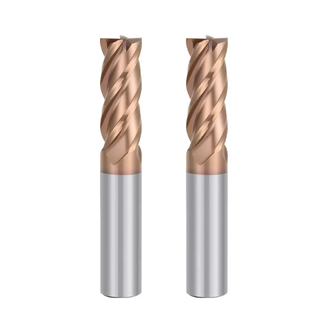
Real-World Mold Steel Machining: End Mill Geometry for HRC 65 Mold Steel
Lab cutting trials and daily production in mold shops are completely different environments. Many toolmakers report impressive tool life on standard test blocks. However, once a tool enters a deep mold cavity, chipping often occurs without warning. Heat-treated injection molds and stamping dies inevitably develop uneven microstructures, causing local hardness to jump between 62 and 66 HRC.
When supporting mold makers across Europe and the US, we never recommend cutting parameters in a vacuum. Mold cavities force cutters into variable widths of cut, interrupted engagement, and severe lateral deflection. If a tool is ground only for smooth, straight-line cuts, cornering will trigger elastic deflection and gouging. A proven HRC65 end mill geometry for mold steel must adapt to dynamic toolpaths in complex cavity corners.
Deep Cavity and Corner Machining: Matching Tool Geometry with Micro-Depth Cutting in Long-Overhang Setups
In Sweden, we assisted a shop milling a 75 mm deep automotive connector insert using a 5:1 length-to-diameter overhang. The machinist played it safe with a 0.02 mm radial width and 0.05 mm axial depth. Even with this delicate cut, the tip chipped continuously in tight corners. Under a microscope, the flank showed fused metal debris instead of a clean wear band.
When feed per tooth drops below the edge hone radius in long-overhang setups, the edge rubs instead of shearing. This elastic pushing generates extreme frictional heat and vibration. In deep corners, we increase primary relief by 1.5° to 2° and tighten edge honing to a strict micron window. Suppressing push-rub chatter with dedicated hardened steel milling tool geometry preserves cutting edges better than raw carbide mass alone.
Rough Slotting vs. High-Speed Light-Cut Finishing: Tailored Geometry Modifications for End Mills
Mold shops often divide operations into high-efficiency trochoidal roughing and high-speed, light-cut finishing. However, trying to run a single cutter across both operations ruins tool economics. Roughing demands high chip-evacuation clearance and heavy impact resistance. Conversely, high-speed finishing prioritizes tight sidewall perpendicularity and fine surface finishes.
We grind differentiated features into each tool to match these contrasting operational demands. For roughing tools, we maximize core thickness, apply a -12° rake, and use unequal flute spacing to damp torque spikes. For finishing cutters, we moderate the negative rake, grind an eccentric relief, and add a micro-corner radius. Changing your toolpath strategy requires updating the end mill cutting geometry at the cutter tip.
Differences Between Hot-Work and Cold-Work Die Steels: Fine-Tuning Tool Geometry for Machining 1.2379 (D2) vs. Hardened NAK80/S136
Shop floors frequently confuse cold-work and stainless mold steels because both reach extreme hardness levels. Cold-work steels like 1.2379 (D2) contain hard, abrasive chromium carbide segregations. In contrast, pre-hardened or quenched stainless steels like S136 are gummy and prone to work hardening. This material difference causes rapid built-up edge (BUE) and micro-welding on the rake face.
We adjust edge prep based on the metallurgical grain structure of each alloy. When milling abrasive 1.2379 steel, we prioritize wedge thickness and wider negative T-lands to withstand hard carbide particles. When milling mirror-grade S136, we mirror-polish the rake face and reduce the hone radius. Tuning your HRC65 end mill geometry to workpiece metallurgy prevents chip adhesion and extends tool life.
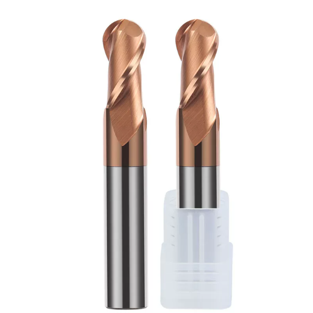
Synergizing Parameters and Coatings: Key Factors for Maximizing the Lifespan of HRC65 Carbide End Mills
A rigid cutter body cannot survive on mechanical geometry alone. Without heat-barrier coatings and tight machine spindle accuracy, tool life drops quickly in production. Cutting 65 HRC steel creates intense mechanical impact alongside friction temperatures over 1000°C. Peak performance requires matching tool geometry with thermal barrier coatings and spindle dynamics.
A dependable HRC65 carbide end mill requires total harmony between carbide grain toughness, rake geometry, coating adhesion, and spindle balance. If coatings delaminate within a few hundred meters, the failure is rarely an isolated coating defect. It usually signals mismatched thermal stress distribution and mechanical chatter across the tool-holder-spindle interface.
The Intersection of Geometry and Heat-Resistant Coatings: Impact of Rake Face Honing on the Adhesion and Flaking Resistance of AlTiSiN-based Coatings
Coatings are not just uniform protective layers sprayed onto raw carbide. In the shear zone of 65 HRC material, cutting edge micro-geometry controls coating lattice integrity. AlTiSiN nanocomposite coatings generate protective aluminum and silicon oxide barriers at 900°C to 1100°C. However, their high hardness and internal residual stress make them vulnerable to substrate surface defects.
Depositing coatings over unpolished ground flutes creates columnar grain defects and stress risers along the cutting edge. This causes early flaking during initial engagement. In our grinding shop, we mirror-polish the rake face and hone the edge to a continuous 10–12 μm radius. This seamless micro-transition provides a secure anchor for the coating, preventing premature delamination under high heat.
From Manufacturing to the Machine Tool: Matching Feed and Speed to On-Site Spindle Rigidity and Runout Tolerances (<0.003 mm)
Machinists often plug catalog speeds and feeds directly into their CNC controllers without checking actual spindle runout. Hardened martensitic steels have zero elongation tolerance. If dynamic runout at the tool tip exceeds 0.005 mm, one or two flutes take the entire cutting load. This spikes the effective feed per tooth and fractures the cutter.
If you run a rigid machining center with shrink-fit holders and runout under 0.003 mm, you can safely run 70–90 m/min at 0.015–0.03 mm/tooth. Under these conditions, controlled friction heat softens the shear zone for productive hard milling. If you run moderate-rigidity spindles or extended reach, you can drop speeds to 45–60 m/min to maintain dynamic balance and prevent chatter.
Three Mandatory Grinding Quality Inspection Standards for Our HRC65 Carbide End Mills
With sixteen years of tooling experience, our primary rule is that uninspected cutters never leave the facility. As a specialized HRC65 carbide end mill manufacturer, we subject every custom batch to three micro-level quality checks after 5-axis grinding. We refuse to transfer manufacturing tolerances and edge risks onto customer machine spindles.
First, we verify edge hone uniformity with a 3D optical profiler, keeping the hone radius within ±1.5 μm along the flute. Second, we verify the symmetry of radial negative rakes and T-land widths to balance cutting loads across all teeth. Third, we verify total radial runout and polish flutes to Ra < 0.1 μm to stop chip packing.
If you are currently milling high-hardness mold steels and battling edge chipping in deep corners, you can review your shop-floor setup. You can send us your part prints, workpiece hardness specs, and cutting parameters. Discussing tool force vectors and micro-geometry engineer-to-engineer is the fastest way to stabilize tool life and eliminate unexpected downtime.