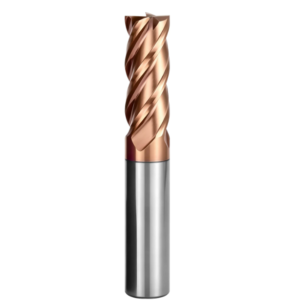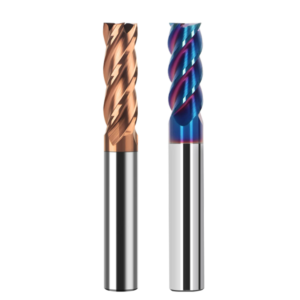
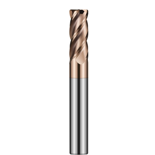
Last month, our technical team resolved a classic failure mode for a Detroit automotive stamping die shop. While finish milling SKD11 punches heat-treated to HRC 62–65, tool life fell off a cliff. Their cutters suffered severe micro-chipping in under 18 minutes, triggering chatter and thermal discoloration across the workpiece.
The client’s lead engineer blamed insufficient coating lubricity and tested high-heat nanocomposites rated above 1,000°C. When we inspected the worn tools under our toolmaker’s microscope, the real culprit was obvious. Failure did not start at the coating layer. It stemmed from chip packing, restricted gullet paths, and severe shock loads directly tied to stock carbide end mill flute design.
Over 16 years as an HRC65 end mill manufacturer, we have seen this mistake play out hundreds of times. Machinists often focus solely on sub-micron carbide grades and exotic coatings. Yet at HRC60+, the shear mechanism shifts from plastic deformation to brittle fracture. That transition makes dedicated HRC65 end mill flute geometry the single most critical factor for heat dispersion and vectoring cutting forces away from fragile edges.
Standard flutes feature wide pockets to evacuate ductile chips. On hardened stock, however, those deep channels slash core mass and kill structural rigidity. Shrinking the flutes too much causes hard, powdery debris to wedge into the gullet, triggering secondary cutting that shatters the carbide. Dialing in end mill flute geometry—from core diameter ratios and negative lands to edge hones—is what separates a cutter that lasts two hours from one that snaps in twenty minutes.
Have you ever faced that frustrating moment on the floor where, despite running premium coatings, your tool screams and chips out within minutes?

Conquering HRC65 Hardened Steel Milling: Why Conventional End Mill Flute Geometry Inevitably Fails on the Shop Floor
If you try to cut HRC 60+ tool steel using standard end mills, the tip will fracture within minutes—even at reduced feed rates. Operators often blame spindle runout or aggressive programming. In reality, it is a straightforward mechanical failure. Conventional flutes are built for soft steels, designed to curl long chips away from the cut.
Hardened steel does not produce curled ribbons. Instead, it generates fine, red-hot abrasive dust. Conventional end mill flute geometry features deep flutes and sharp positive rake angles. Under hard milling loads, this profile increases tool deflection. The cutting edge lacks backing support, tensile stress exceeds the carbide’s transverse rupture strength, and the edge chips immediately.
The Core Conflict in Hardened Steel Flute Geometry: Insights from a North American Mold Maker’s SKD11 Machining Issues
That Detroit shop was finishing critical punch walls in SKD11 (HRC 63–65). They were using standard 4-flute finishing tools from a tier-one catalog. The coatings were rated for 1,100°C, yet the tools failed to hold surface roughness (Ra) tolerances. The root cause was severe mechanical stress cracking right along the flute base.
This case highlights the core dilemma in hardened steel flute geometry: balancing chip clearance against cross-sectional rigidity. SKD11 is packed with hard alloy carbides that amplify tool vibration. We redesigned their tool core, sacrificing some theoretical chip volume to gain over 30% static stiffness. Tool life immediately jumped from a single part to five finished parts per cutter.
Balancing Rigidity and Chip Clearance: Critical Empirical Data on Core Diameter for High-Hardness Machining
Engineers frequently ask us: “Why not grind micro-shallow flutes to maximize tool stiffness?” Our grinding records prove that this approach backfires. On 10mm end mills, a core diameter ratio below 62% causes measurable tool deflection at just 0.1mm radial engagement. However, pushing that core beyond 70% creates a different disaster.
A 70%+ core turns the tool into a rigid punch, but it chokes the chip gullet. Hot, powdery chips cannot evacuate the tight flute trough. Friction spikes instantly, stripping the PVD coating and welding chips to the flute. For HRC65 steel, we target a 65% to 68% core ratio. On tools below 4mm, we hold 68% for rigidity; on tools above 8mm, we drop to 64%–66% with polished gullets to maintain air clearance.
Passivation via Negative Rake Design: Counteracting Interrupted Cutting Impacts on Hard Materials
Sharp positive edges work wonders on mild steel by slicing smoothly through the shear plane. At HRC65, however, razor sharpness equals instant brittleness. For hard milling, our carbide end mill flute design replaces positive rakes with a -5° to -12° radial negative rake, backed by a micro-honed negative T-land at the cutting edge.
This negative geometry redirects cutting forces inward. It converts dangerous tensile stress into compressive stress, which solid carbide handles exceptionally well. We pair this profile with an asymmetric waterfall edge preparation of 10 to 15 microns. Anything below 8 microns chips on hard carbide inclusions; anything above 18 microns pushes radial forces too high and causes rapid thermal wear.
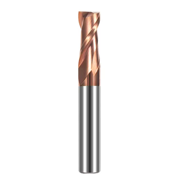
Real-World Performance Comparison: 2-Flute vs 4-Flute vs 6-Flute High-Density End Mills in Hard Milling
Shop machinists constantly debate the best flute count for hardened mold steels. Veterans often lean on a single 4-flute cutter for every job. Meanwhile, high-speed programmers prefer 6-flute or 8-flute tools for fine surface finishes. Testing hundreds of production setups taught us that no single tool fits every stage. Choosing the right end mill flute count is a direct trade-off between chip pocket clearance and core rigidity.
Moving from a 2 flute vs 4 flute end mill to a 6-flute tool thickens the core and multiplies cutting contacts per minute. This jump delivers mirror-like finishes, but it drastically shrinks the chip gullet. If radial engagement spikes, fine hot chips cannot escape before the next edge hits. Trapped chips create thermal extrusion, causing catastrophic blowout on high-flute cutters.
Avoid Forcing 4-Flute Cutters into Deep Cavities in Hardened Steel: The Impact of Flute Count on Heat Accumulation During Side Milling and Corner Cleanup
Machinists often assume a 4-flute cutter’s rigidity makes it safest for clearing deep corners. In high-hardness steels, this choice traps heat instantly. On an injection mold slider with cavity depths over three times the diameter, a client ran a 4-flute tool at low feed. Within ten minutes, poor air evacuation annealed the tips to a dark purple, ruining the cutter.
For deep, semi-enclosed corners, selection logic must flip: drop down to a 3-flute or reinforced 2-flute tool. A 2-flute cutter has a thinner core, but its wide chip gullet lets compressed air hit the cutting zone directly. This airflow ejects 800°C abrasive chips immediately. Running high spindle speeds with a light feed (fz 0.008–0.015 mm) gives a 2-flute tool far longer life in deep pockets than a choked 4-flute tool.
Selection Criteria for 4-Flute vs 6-Flute End Mills HRC65 for Cold-Work Die Steels like SKD11
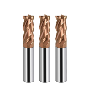
High-carbon, high-chromium cold-work steels like SKD11 and D2 contain dense eutectic carbides that spike cutting resistance. In our custom tooling setups for European mold makers, we draw a hard line between 4-flute and 6-flute applications. For semi-finishing, corner clearing, or radial depths of cut between 8% and 15% of the cutter diameter, a 4-flute design remains our safe ceiling because it provides enough chip clearance during interrupted cuts.
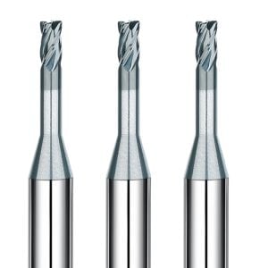
When switching to high-speed finishing to remove the final 0.03 to 0.05 mm, specialized HRC65 end mill flute geometry for SKD11 favors a 6-flute build. SKD11 chatters easily during micro-engagement. A 6-flute tool features a massive 70% core and shallow parabolic flutes, creating the rigidity needed for mirror finishes at 20,000 RPM. However, machine runout must stay under 3 microns to prevent narrow gullets from packing with chips.
Cycloidal Milling and High-Feed Conditions: Real-World Shop-Floor Experience Using Variable Pitch to Eliminate Chatter
Full-flute side milling with uniform flute spacing often triggers ear-piercing spindle screams and washboard chatter marks. While tuning a hardened-steel aerospace setup, our team found 0.02 mm surface ripples during cycloidal passes, even on a high-rigidity machining center. This problem is resonant phase superposition: identical tooth entry intervals continuously amplify cutting force waves between the tool and workpiece.
Grinding an asymmetric variable pitch into the tool geometry disrupts this harmonic cycle at the physical source. Shifting uniform 90° spacing to an alternating 88°/92° spacing scatters tooth impact frequencies. On the shop floor, this geometry suppresses resonance, lowers cutting noise by 5 dB, and lets you push axial depth of cut to 1.5 times the tool diameter in trochoidal paths without chatter.
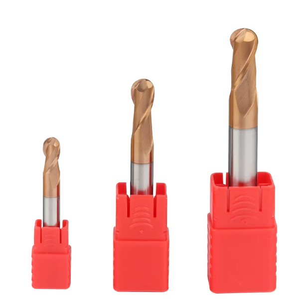
Flute Cross-Section and Chip Evacuation: Practical Control of Heat Transfer via Carbide End Mill Flute Design
During dry milling of hardened steel, chips and sparks fly off in dark red or blue streams. Many operators assume the PVD coating absorbs all that thermal punishment alone. In reality, cutting thermodynamics show that chips carry away over 80% of generated heat. Poor flute curvature traps 1,000°C abrasive dust along the flute wall, forcing heat back into the carbide substrate and stripping the coating.
Our carbide end mill flute design treats the flute as a thermal exhaust duct rather than an empty pocket. By blending the gullet radius and involute opening angle, we direct hot chips along the shortest escape path. Minimizing contact time between incandescent chips and the tool body cuts thermal shock to the cutting edge, securing dependable dimensional stability during dry hard milling.
Helix Angle (35° vs. 45°) Analysis: The Relationship Between Axial Force Distribution and Chatter Marks When Milling HRC65 Material
Clients frequently ask whether they should run a 35° or 45° helix angle on hardened steel. A 45° helix eases entry impact and cuts smoothly in soft steels, but on HRC65 material it generates massive upward axial pull. We saw this on a BT40 spindle running a 45° tool on deep walls: high axial forces caused microscopic tool pullout in the collet, leaving fish-scale chatter marks and tripping spindle sensors.
For balanced stability on an HRC65 carbide end mill, we recommend a moderate 35° to 38° helix, or an unequal 38°/41° setup. Trimming the helix angle sacrifices a fraction of slicing smoothness, but it drops axial pulling force substantially. This keeps cutting loads aligned with the machine spindle’s stiffest radial axis, wiping out micro-chatter during long-reach finishing.
Flute Mirror Polishing: How Micron-Level Chip Friction Affects Dry Milling Chip Evacuation
Tool buyers often judge a cutter by its outer grind, but our CNC grinders spend the most wheel-dressing time inside the flutes. Under a microscope, an unpolished flute shows grinding ridges around Ra 0.4 μm. These tiny grooves mean little in soft steel, but in dry hard milling, powdery chips pack into them instantly, welding into built-up edge formations.
Applying flute mirror polishing down to Ra 0.1 μm stops chip sticking at the microscopic level. Smooth gullet surfaces cut friction, allowing cold compressed air to blast chips out with minimal backpressure. Our shop tool-life tracking shows that mirror-polished flutes lower dry cutting friction heat by 15%, substantially slowing crater wear on the rake face.
Ultra-Fine Carbide Substrate Combined with Streamlined Flute Geometry: Preventing Thermal Stress-Induced Micro-Cracks at the Flute Root
Cutting zone spikes above 800°C followed by cold air blasts create severe thermal fatigue. Standard carbide grades develop micro-cracks along grain boundaries under this shock. We grind from sub-micron carbide rods (0.2–0.4 μm grain size) with low cobalt content for extreme hardness, but this dense structure is vulnerable to stress notches at the flute bottom.
To prevent fractures, hardened steel flute geometry requires seamless tangential blending between the core and flute floor. Any sharp grind transition concentrates expansion stress right at the root, snapping flutes off at the neck. Blending smooth, notch-free gullets with an ultra-fine grain substrate distributes thermal loads across the flute curve, eliminating sudden cutter breakage.
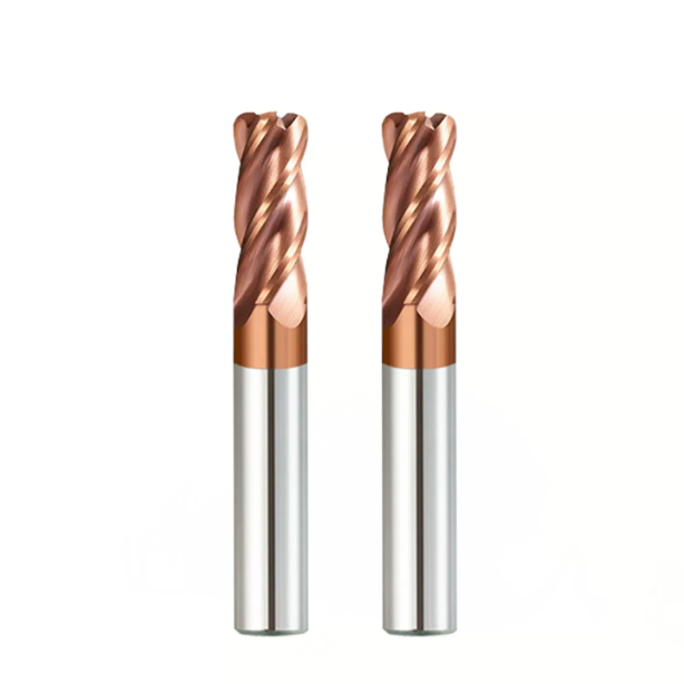
Microscopic Wear Analysis: Typical Wear Patterns on HRC65 End Mills Caused by Flute Design Flaws
When tool life tanks during production runs, machine shops usually blame coating peeling or a soft carbide grade. But when we put failed tools under a 3D digital microscope, the truth becomes clear. Fracture angles, adhered workpiece smear, and flaking zones reveal the dynamic stress balance during the cut. Most of these failure modes trace straight back to flawed flute profiles.
In hardened steel, an unbalanced flute disrupts the cutting tip’s support zone and spikes localized stress. Examining real-world HRC65 end mill tool wear, uniform abrasive wear is practically a myth. Instead, shops battle early mechanical cracking and thermo-mechanical fatigue from trapped chips. These micro-cracks propagate in seconds, wiping out the cutting edge.
Chip Compression Caused by Narrow Flutes: Tracing the Origins of Chipping and Initial Micro-spalling
We investigated a tooling failure for an automotive fixture builder where cutting edges broke into serrated teeth within thirty minutes. Under magnification, the damage did not start at the cutting tip. It began as heavy scoring on the rake face right at the flute root. The flute cross-section was ground too narrow in a flawed attempt to maximize tool rigidity.
Because the channel lacked adequate clearance, rock-hard chips wedged tight against the carbide body. When chips pack, chipping quickly escalates from micro-pitting to total edge blowout. Trapped chips apply reverse radial forces against the incoming cutting edge. Combined with forward machine feed, this shear load tears coating and carbide grains away in sheets.
H3: Flank Wear and Thermal Phase-Change Wear: Optimizing Chip-Breaker Geometry to Facilitate Nanocoating Heat Dissipation
Seeing heavy galling and scoring on the clearance land, programmers often demand thicker PVD coatings. But above HRC 60, coatings must stay ultra-thin to prevent delamination. Your flute profile does the heavy lifting for thermal control. If the flute entry angle is too steep, 900°C cutting heat cannot escape with the chip stream, bleeding straight into the tool substrate.
When flank wear shows signs of thermal melting, an optimized flute profile rescues the coating. We grind a smooth relief radius between the primary relief land and the flute heel. This creates an open channel for cold compressed air while generating turbulent air vortices in the gullet. These currents help AlTiN nanocomposite coatings dump heat fast, keeping the substrate from softening.
On-site Troubleshooting Guide: Inferring Chip-Flute Compatibility via Chip Morphology
The fastest diagnostic tool in your shop is the chip splatter on your machine enclosure glass. In balanced hard milling, chips look like dry, silvery, needle-like slivers. This proves the workpiece material sheared cleanly via brittle fracture and flew out on the air stream. That morphology confirms your flute depth, rake angle, and feed per tooth are working in harmony.
If you find dark blue, black, or sintered chip clusters in the conveyor, shut the machine down. Blue chips mean debris is dwelling inside the gullet and welding during flow transitions. It signals poor flute clearance or excessive chip load driving heat back into the tool. Cranking spindle speed here will only trigger a catastrophic spindle load spike within minutes.
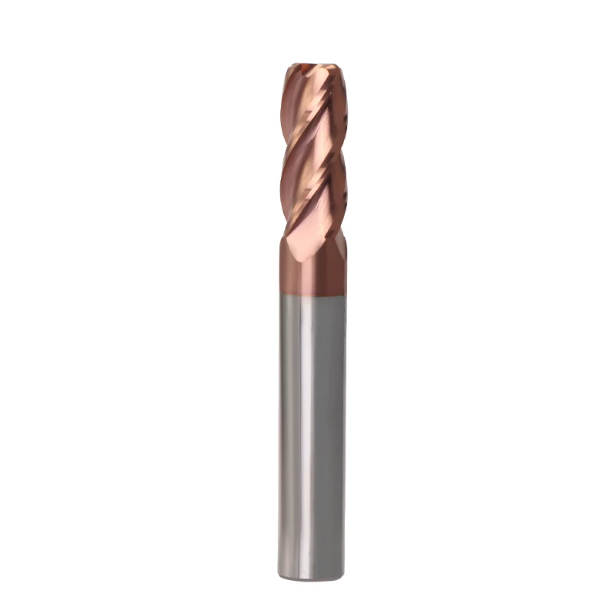
Frontline Solutions from a Custom Workshop: How an HRC65 End Mill Manufacturer Fine-Tunes Flute Geometry for European and American Markets
Standard catalog tooling is engineered as a mechanical compromise—a safe middle ground for average conditions. Over our years serving European and American mold shops as a specialized HRC65 end mill manufacturer, we learned that one generic flute profile cannot cover every machine dynamic. True breakthroughs come from custom grinding: micro-adjusting core diameters, offsetting flute indexing, and polishing flute bottoms.
Massive tool life gains rarely require exotic, expensive blank materials. Instead, you need a tool profile built around your exact machining strategy. Combining negative micro-honed lands, tuned helix angles, and mirror-finished flutes balances chip clearance with deflection resistance. This custom engineering is the real secret to eliminating chronic edge failures on the production floor.
Custom HRC65 End Mill Flute Design Case Study: Batch Finishing of Hardened Stamping Dies for a German Automaker
A stamping shop in Stuttgart was finishing large automotive trim dies cast from 1.2379 (D2) steel hardened to HRC 64–65. Using standard European 4-flute end mills at a 4xD overhang, the tools developed chatter waves on vertical walls. Worse, thermal wear dulled the cutting tips after just two dies. Dropping feed rates would have wrecked their customer delivery deadline.
After reviewing their spindle dynamics and chip formation, we engineered a dedicated HRC65 end mill flute design. We shifted to variable flute spacing (88°/92°) to break resonance, dropped the helix angle to 37° to kill axial pull, boosted the core to 67%, and mirror-polished the flutes. At identical cutting speeds, tool life jumped 2.5 times, completely eliminating sidewall chatter and premature chipping.
A Pitfall-Avoidance Checklist for CNC Programmers: High-Speed, Ultra-Low Radial Depth (ae) Strategies Paired with Specialized Hard-Milling Flute Geometries
If you program hard milling toolpaths, remember: specialized flute geometry requires a matched cutting strategy. If you are milling tool steels above HRC 60, then you should run high-speed trochoidal paths. Keep radial cut width (ae) strictly between 2% and 5% of tool diameter, while pushing axial depth (ap) up to 1.5xD. This ultra-thin chip method traps cutting heat inside tiny needle chips and ejects it instantly.
If you are clearing deep pockets with long overhangs, then you should drop 4-flute tools for reinforced 2-flute or variable 3-flute designs. Keep feed per tooth between 0.008 mm and 0.015 mm, using high RPM to maintain surface speed. If you are struggling with chipped edges on hard steels, check your chip color and setup rigidity. If you have challenging part prints or stubborn tool breakage issues, let us know your specific machine setup so we can dial in the right flute geometry.