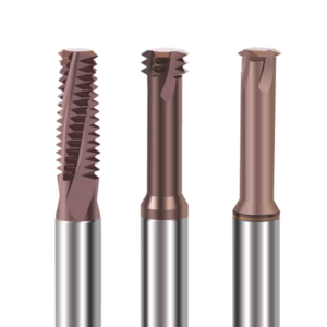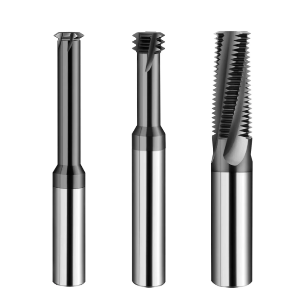
Last month, a client in Stuttgart specializing in spinal implants sent us an urgent email. They were machining M1.4×0.3 blind-hole internal threads on 316LVM bone screws using a Swiss-type lathe. The micro-tap snapped at the bottom of the hole on the 23rd piece, instantly scrapping a semi-finished component worth over €80.
We have seen this scenario play out hundreds of times over the past fifteen years. In the M1 to M3 range, traditional tapping in medical alloys is a gamble. Extreme work hardening, high shear strength, and restricted chip evacuation easily exceed the torsional strength of a slender tool. Even without breakage, elastic spring-back and thread taper often cause parts to fail Go/No-Go inspection.
That is why we actively assist medical contract manufacturers in upgrading their shop floors. For high-value, thin-walled medical components, thread mills for stainless steel are no longer an optional upgrade. They are the only repeatable way to lock in a consistent 99%+ yield rate on micro-machining lines.
As a dedicated solid carbide thread mill manufacturer, we know what it takes to grind micro-tools at a microscopic level. We balance transverse rupture strength in ultra-fine substrates, apply heat-resistant nanocomposite coatings, and optimize geometry to minimize radial load. Yet, the tool itself is only 30% of the battle; the other 70% comes from mastering feed compensation, arc-in toolpaths, and multi-pass strategies.
Are you tired of watching your Swiss lathe trip an alarm on another ruined bone screw, wondering why your micro-tooling never survives past the 500-part mark?
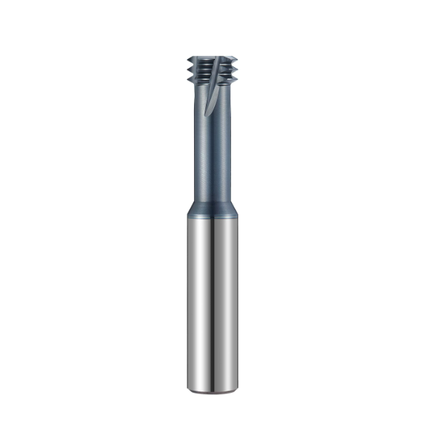
Why Do We Recommend Replacing Taps Entirely with Carbide Thread Mills for Micro-Threading 316LVM and High-Hardness Alloys?
Machining precipitation-hardening stainless steels like 17-4PH or Custom 465 is vastly different from cutting austenitic 316LVM, but both share two brutal traits: severe work hardening and high cutting resistance. Many programmers stick with micro-taps out of habit because the G-code is simple and cycle times appear short. In M1–M3 holes, however, the excessive contact area causes cutting torque to spike rapidly, easily exceeding the shear strength of slender shanks.
Taps work fine on free-machining brass or aluminum, but on high-value medical screws, a snapped tap ruins the entire part and stalls the line. When we help medical contract shops convert their processes to high-performance carbide thread mills, we break that excessive torque down into manageable, light helical passes. This shift eliminates catastrophic failure and gives production managers complete, predictable control over their tool life and scrap rates.
Zero Tolerance for Broken Tools in Medical Bone Screw Production: Eliminating Scrapped Implants Caused by Micro-Tap Breakage
Few things are more frustrating on a machine shop floor than seeing an EDM machine tied up trying to burn a broken tap out of a complex bone screw. After turning, deep-hole drilling, and Torx broaching, a sudden tap failure turns an expensive finished component into immediate trash. Beyond the scrap cost, a broken tap often damages the live tooling spindle, collet, or tool setter.
Thread milling fundamentally changes the safety equation because the tool diameter is always smaller than the hole minor diameter. Even if an edge chips or wears out prematurely, the cutter never seizes inside the part. The chips or broken tool can simply be flushed out with air or oil, leaving the screw undamaged. Equipping your machines with dedicated thread mills for stainless steel is less about shaving two seconds and more about buying complete process security.
Eliminating Deformation from Forming and Cutting: Using Specialized Thread Cutters to Prevent Outer Diameter Expansion in Thin-Walled Micro-Tubing
If you run hollow cannula screws or catheter connectors with wall thicknesses under 0.35 mm, you know how easily thin walls distort. Cold-forming taps rely entirely on material displacement, and the resulting radial hoop stress will quickly bulge or crack the outside diameter. Cutting taps are barely better, generating enough radial pressure to push thin walls out of round by more than 0.015 mm.
To protect delicate parts, we set up our jobs with a specialized miniature thread cutter tool. Because helical interpolation allows you to take shallow radial cuts of only 5 to 15 microns per pass, cutting forces stay extremely low. Combined with smooth climb milling, this method eliminates wall expansion entirely, holds true concentricity, and delivers a clean surface finish below Ra 0.2 that no tap can match.
Precision Bottoming of Full-Length Blind-Hole Threads: A Practical Case Study on Swiss-Type Lathes with Minimal (0.5P) Clearance
Programming blind micro-holes on a Swiss turn gang slide often leads to a major bottleneck: the blueprint demands full thread depth almost to the bottom of the drill point. Many implant screws leave less than 0.5 pitches (0.5P) of axial clearance. Miniature taps need a lead chamfer of 1.5P to 2.5P, forcing operators to bottom out dangerously close to the floor, which invites instant tool breakage if chips pack the bottom.
We solve this tight-clearance challenge by utilizing a dedicated flat-bottom cnc thread milling bit with a minimal corner radius. By positioning the cutter just 0.1 mm above the hole floor and interpolating upward toward the entry, high-pressure oil flushes chips out ahead of the cut. This bottom-up strategy cuts clean, full-profile threads down to the final fraction of a pitch without risking bottom impact or packing chips.
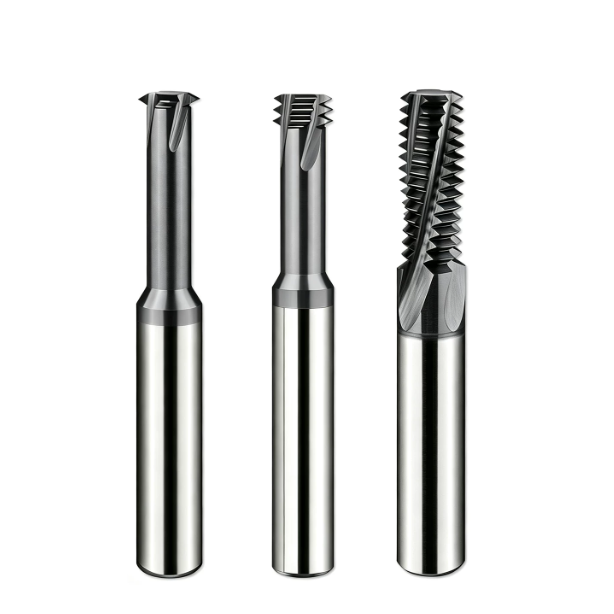
A Tool Manufacturing Perspective: Our Geometric Design Principles for Solid Carbide Thread Mills with Micro-Diameters and Micro-Cutting Edges
Shop floor supervisors often ask us why standard 0.75 mm diameter cutters can yield radically different tool life in identical M1 holes. Catalog specs only tell half the story. In micro-cutting zones under 1 mm with overhang ratios exceeding 3×D, cutting forces in austenitic stainless steel quickly trigger severe tool deflection or sudden brittle fracture.
As a dedicated solid carbide thread mill manufacturer, we never simply downscale macro-tool profiles. Slender micro-cutters require maximum core stiffness, immediate thermal dissipation, and microscopic edge precision. Dialing in these critical grinding parameters at our facility is what establishes a reliable, repeatable machining window on your CNC machines.
The Delicate Balance Between Core Thickness and Chip Flutes: Optimizing Flute Design for Torsional Rigidity in M1–M3 Micro-Tools
When designing micro-tools for medical implant clients, the biggest debate usually centers on the core-to-diameter ratio. Some programmers demand oversized flutes to clear chips in blind holes. However, on micro-tools below M1.6, cutting flutes too deeply strips away cross-sectional inertia, causing torsional chatter and rough thread flanks in gummy 316L.
Through extensive cut testing, we moved away from deep U-shaped flutes on our miniature carbide thread mills. Instead, we grind a shallow, variable-curvature flute that maintains a rigid core ratio of 58% to 62%. This geometry preserves critical bending resistance, completely eliminating the tapered pitch diameters and wall deflection common in deep micro-bores.
Real-World Performance of Ultrafine-Grain Substrates and Nano-Coatings: High-Temperature BUE Resistance and Nano-Honing for Austenitic Steels
Examine discarded micro-tools under a microscope, and you will rarely see normal abrasive flank wear. Most micro-cutters fail because built-up edge (BUE) tears away the microscopic edge radius. Stainless steel generates intense local heat above 700°C; if an edge is razor-sharp, it chips from thermal shock, but over-honing work-hardens the workpiece immediately.
We grind our tools from sub-micron carbide (0.2–0.4 µm grain size) to balance extreme hot hardness with edge toughness. We then apply a controlled 2–4 micron micro-hone and a silicon-rich nanocomposite coating. This smooth barrier prevents chip welding during high-precision thread milling stainless steel, ensuring the cutting edge survives repeated thermal cycles without micro-chipping.
Strict Control of Runout to Within 0.002 mm: The Direct Impact of Manufacturing Concentricity on Micro-Threading Tool Life
On large parts, 5 microns of runout simply degrades your surface finish slightly; in micro-threading, 5 microns is a death sentence. When cutting an M1.4 thread, your actual chip load may only be 3 to 5 microns per tooth. If dynamic runout exceeds 3 microns, one flute carries triple the load while the other rubs and work-hardens the bore.
To prevent premature failure, every micro threading cutting tool we produce undergoes non-contact optical inspection to guarantee total runout under 0.002 mm. We always caution our shop-floor peers: mounting a high-precision tool into a worn ER collet ruins its performance. You must pair micro-cutters with precision shrink-fit or hydraulic holders to preserve edge life.
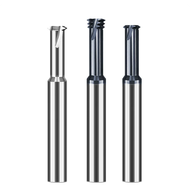
Practical Tips for Swiss-Type Lathes: Toolpaths and Programming Compensation for M1–M3 Thread Milling Stainless Steel
Machining micro-threads on Swiss-type lathes requires a completely different approach than programming a rigid vertical machining center. Compact driven-tool spindles have limited bearing mass and lower torsional damping. Paired with slender tool shanks, any sudden chip surge or entry shock immediately produces deflection and dimensional errors.
In our field troubleshooting, premature micro-tool failure almost always stems from rough toolpath generation rather than spindle speeds. For micro-parts, smooth toolpath motion matters far more than machine brand. Achieving continuous, trouble-free thread milling stainless steel requires gradual entry filtering, balanced radial depths, and proper CNC feed compensation.
Eliminating Tool Marks and Impact Chatter: Why We Mandate Tangential Arc Entry (Arc-in/Arc-out) During On-Site Commissioning
Many shops program a straight plunge (X-axis vector) into the bore to keep macro-programs simple. On free-machining brass this shortcut might pass, but in tough stainless steel, a straight plunge slams the micro-flutes into material instantly. This sudden impact leaves heavy witness marks on the wall, rattles the spindle, and micro-fractures the cutting edge.
We always mandate a smooth 90-degree tangential arc-in with a synchronized helical z-ramp, followed by an equivalent arc-out exit. This entry geometry allows cutting resistance on the carbide thread mills to build gradually from zero to full load. The tool exits just as cleanly, preventing exit burrs and ensuring the thread profile passes tight optical inspections.
Radial Pass Strategy: Avoiding Single-Pass Heavy Cuts for 17-4PH and Custom 465 Alloys
Attempting to cut full thread depth in a single pass on 44 HRC precipitation-hardening stainless is a guaranteed way to snap a cutter. These alloys work-harden rapidly under pressure, and full-depth cuts overload slender tool necks. The severe lateral deflection produces tapered threads that fail Go-gauge inspection—or snaps the tool before completing a single turn.
We recommend splitting the radial depth into two roughing passes and one zero-load spring pass. For an M2×0.4 profile, take 65% depth on the first pass, 35% on the second, and finish with a spring pass at the final pitch diameter. This step-down strategy shields your micro thread cutter tool from peak cutting forces and clears taper completely.
Tool Center Path Conversion: Preventing Instant Chipping of Micro CNC Thread Milling Bits Caused by Feed Compensation Errors
This is the most common programming error we see when machinists move from mills to Swiss-type lathes. Control units like Fanuc or Mitsubishi calculate programmed linear feed (F) at the tool center path, not at the cutting edge periphery. In tiny bores, the tool center path radius is dramatically smaller than the actual thread major diameter.
If internal circular feed compensation is disabled in your CAM post-processor, the controller applies the edge chip load directly to the centerline. This mistake can easily double or triple the actual chip load at the cutting edge. For a delicate micro cnc thread milling bit, this instant overload breaks the tool on the first revolution; always double-check your compensated feed rates before pressing cycle start.
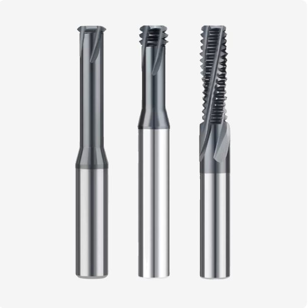
Conquering Tool Deflection and Tolerance Issues: On-Site Solutions for Thread Mills for Stainless Steel
Few things frustrate quality inspectors and machinists more than failing thread Go/No-Go tests on micro medical screws. Typically, the Go gauge turns smoothly for the first half-pitch before seizing completely at depth, while the No-Go gauge enters the hole mouth too loosely. This discrepancy is rarely a simple calibration error; it stems directly from physical tool deflection during helical milling.
Austenitic and martensitic stainless steels have low elastic moduli and high yield strength, meaning slight radial forces easily flex slender tool necks. Operators often try to compensate by adjusting the global D-offset, but this only creates a trade-off between an oversized entry and an undersized bottom. When tolerances span only a dozen microns, applying thread mills for stainless steel requires dedicated toolpath compensation to cancel out mechanical deflection.
Eliminating the “Loose Top/Tight Bottom” Taper: Practical Compensation Adjustments for Micro Thread Cutters
When thread depth reaches 3×D or 4×D, tooth design directly determines the severity of part taper. Full-profile multi-tooth cutters seem efficient because they finish the profile in one helical pass, but engaging multiple teeth in gummy 316L generates excessive lateral push. The resulting deflection starves the tool tip of cutting depth, leaving an invisible taper that wedges the Go gauge.
For deep micro-holes, switching to a single-tooth thread cutter tool reduces cutting pressure by more than 60%. If cycle times require a multi-flute tool, program a stepped taper compensation into your subroutines. Expanding the interpolation radius outward by 0.002 mm for every 0.5 mm of Z-depth dynamically shaves off residual taper, ensuring the gauge spins smoothly to the bottom.
Medical Cleanliness and Deburring Solutions: Eliminating Micro-Burrs on M1–M3 Thread Crests in Swiss Lathes
Micro-implants cannot have loose burrs or folded crest edges under cleanroom inspection microscopes. Manual deburring with picks or brushes after ejection is slow, risks scratching precision crests, and leaves loose debris inside blind micro-holes. Medical parts demand an automated, repeatable deburring sequence executed entirely inside the machine envelope.
We program miniature carbide thread mills into an automated sequence: drill, chamfer, thread, and final deburr. Milling the thread after chamfering the pilot hole ensures clean crest definition. A final, zero-depth spring pass at the entry with the thread cutter cleanly shears away displaced micro-burrs, producing an implant-grade surface right off the sub-spindle.
Tool Holder Rigidity and High-Pressure Coolant Configuration: Securing Reliable Micro-Hole Chip Evacuation
Holding 3 mm or 4 mm micro-shanks in worn ER11 collets guarantees poor tool life and inconsistent sizes. Standard collet assemblies routinely introduce 0.008 mm of runout, which instantly exceeds the delicate chip load per tooth. Flooding the outside of the part with low-pressure oil is equally ineffective because surface tension keeps oil from reaching the bottom.
When chips pack the bottom of a hole, a rotating cnc thread milling bit will shatter within a fraction of a second. We mandate high-precision shrink-fit or hydraulic holders to keep total dynamic runout under 0.002 mm. Pairing this setup with an 80-bar high-pressure oil jet aimed directly along the tool flutes blasts chips out continuously and protects the micro-cutting edges.
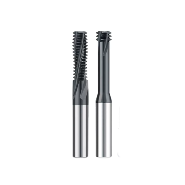
Customer Workshop Case Study: Yield and Cycle-Time Gains with Custom CNC Thread Milling Bits
The scrap bin behind a Swiss-type lathe is the ultimate test of any tooling strategy. We frequently visit medical machine shops running top-tier Swiss turns that still choke on M1 to M3 threads in tough alloys. Rapid flank wear, bore taper, and broken tools constantly force operators to interrupt production for tool offsets and manual inspections.
Eliminating these headaches simply requires matching the tool’s core geometry and toolpath to the exact workpiece conditions. When shops replace off-the-shelf catalog tools with an application-specific cnc thread milling bit, the results are immediate. Bore taper disappears, tool life stabilizes, and operators can confidently let the machines run unattended through lights-out shifts.
Swiss-Turn Machining of 316L Spinal Screws (M1.6×0.35): Boosting Tool Life from 80 to 450 Parts
A contract shop in the Swiss Jura Valley struggled with an M1.6×0.35 internal thread in 316L spinal screws on a Citizen lathe. Using an off-the-shelf micro-cutter in a single radial pass, chip packing and deflection chipped the flutes after just 80 parts. Operators spent half their shifts re-setting tools and sorting out rejected screws.
We divided the cutting path into two radial passes (60% and 40% depth) and added a 0.002 mm spring pass to clean the taper. We then switched from external flood coolant to an 80-bar high-pressure oil line and mounted our reinforced carbide thread mills. Milling time increased by only 1.8 seconds, while usable tool life surged from 80 to over 450 screws per tool with a 99.4% yield.
Serving Global Medical Manufacturers: Delivering Custom Solid Carbide Thread Mills to Print in 48 Hours
If you are struggling with thin-walled bone screws, 46 HRC alloys, or narrow relief grooves, you do not have to settle for catalog compromises. Off-the-shelf tools include excessive flute lengths and generic clearances that invite chatter and deflection in tight bores. Custom geometries eliminate that flex by maximizing shank rigidity for your exact hole depth.
As a specialized solid carbide thread mill manufacturer, we know how crucial quick turnaround times are for medical device pre-production runs. Send us your component print, material grade, and holder specifications, and we can calculate the optimal core diameter and grind custom micro-cutters within 48 hours. If challenging micro-threads are bottlenecking your shop floor, let’s look at your drawings and dial in the cutting data together.