
Last month, we received an urgent call from an engineering manager at a precision injection mold shop in Germany.
His crew was finishing an S136 mold core—hardened to 54 HRC and valued at over $30,000—on a vertical machining center. An operator tried cutting M6 blind-hole cooling threads using a premium solid-carbide tap. The tap bound, twisted, and snapped deep in the hole. Burning it out via EDM meant wasting half a shift and risking thermal stress cracks across a high-polish finish.
Over fifteen years of manufacturing tooling and supporting machining facilities across North America and Europe, we have seen this final-stage disaster far too often.
Whether it is abrasive D2 cold-work steel at 58–62 HRC, thermal-fatigue-prone H13 at 48–52 HRC, or corrosion-resistant S136, everything changes once steel crosses 50 HRC. Cutting forces surge, edge temperatures exceed 1,470°F (800°C), and chip clearance vanishes. Relying on taps in these conditions is a pure gamble that risks thousands of dollars to save a few seconds of cycle time.
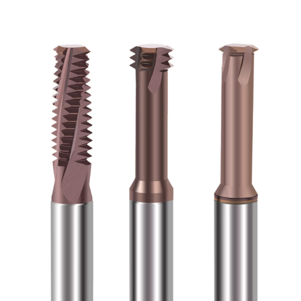
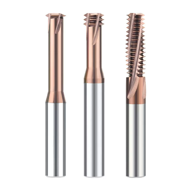
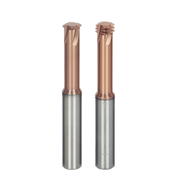
That is why we standardized on thread milling cutters for hardened steel across our production lines and client shops. Hard milling is never about brute force. It relies on light radial cuts, high surface speeds, and controlled helical interpolation to generate tiny, manageable chips. By pairing heat-resistant nanocomposite coatings with negative-rake micro-geometries in shrink-fit holders, a carbide thread milling cutter maintains pitch diameter and runout within tenths while keeping your parts safe.
When you machine these three distinct tool steels, does your machine spindle squeal, chatter, or chip teeth unexpectedly during thread cycles? More often than not, the culprit is an incorrect entry vector, poor tool selection, or an uncompensated internal circular feed rate.
Why We Stopped Tapping and Standardized on a Carbide Thread Milling Cutter for Hardened Mold Steels
Eight years ago, we pulled taps from every hardened component setup in our shop and urged our mold-making clients to do the same. Machinists often push back because rigid tapping appears ten to fifteen seconds faster on paper. However, that margin disappears the moment you factor in rework, EDM burn-outs, or scrapped inserts. Chasing seconds on hardened steel is simply not worth risking the entire block.
Process reliability boils down to your Cpk and safety margin under extreme loads. At 50+ HRC, a tap’s massive surface contact creates instant torque spikes and severe heat build-up. If blue, micro-fine chips pack the flutes or the bore drifts slightly from heat-treat distortion, the tool snaps instantly. Switching to a dedicated carbide thread milling cutter provides point-contact clearance, keeping cutting forces predictable.
The Cost of a Broken Tap in Finished H13 and D2 Inserts
Every mold shop manager knows the sickening sound of a tap breaking in a nearly finished block. You spend dozens of hours roughing and high-speed finishing an H13 insert or a carburized D2 slide (58–62 HRC), only to snap an M8 tap on the final thread. The spindle retracts empty, leaving broken carbide wedged tight inside the hole. The entire production schedule grinds to an immediate halt.
A stamping client in Michigan learned this lesson the expensive way. Rushing an urgent job, they tapped deep holes into a massive D2 die shoe using premium coated taps. The tap fractured under excessive torque, and subsequent EDM burning left a recast layer and micro-cracks across the critical sealing face. That scrapped part settled the debate: they banned taps and standardized on thread milling hardened steel for all die details.
Eliminating Workpiece Scrap with the Right Thread Milling Cutter Tool
Machine spindles never run in textbook conditions; tools inevitably wear and lose microscopic carbide grains. The real advantage of an engineered thread milling cutter tool is that it downgrades total part scrap into a manageable size adjustment. Because the cutter diameter is considerably smaller than the pre-drilled bore, chips flush out freely and the tool never binds against the walls.
Even if an operator misses a tool-life warning and the cutting edges chip, the mold insert remains completely safe. If the thread gage runs tight, you simply enter a 0.02 mm wear offset in the CNC control for a spring pass, or index to a new tool. The bore stays on location, the thread flanks stay smooth, and your expensive mold core avoids the scrap bin.
Material-Specific Strategies: Thread Milling Hardened Steels (H13, D2, and S136)
Using identical speeds, feeds, and toolpaths across all hardened die steels will quickly backfire. When troubleshooting setups on-site, the most common mistake we encounter is assuming that similar Rockwell hardness numbers mean identical cutting behavior. Even if an insert and a cavity block both test at 52 HRC, their shear stress profiles and heat generation differ completely based on alloy chemistry and carbide structure.
Selecting the right thread milling cutters for hardened steel is only the first step. Success depends on adapting your cut to the specific metallurgy of each steel grade. Coarse carbides in cold-work steels demand high edge toughness, hot-work alloys challenge your thermal management, and stainless mold steels punish hesitant entry moves. Dialing in parameters requires knowing how each alloy behaves under microscopic shear strain.
Tackling Abrasive Wear in D2 Cold-Work Die Steel (58–62 HRC)
D2 is packed with hard, undissolved eutectic carbides dispersed throughout the hardened matrix. When running a carbide thread milling cutter along a helical path, these abrasive carbide particles act like tiny grinding wheels hammering the cutting edge. Pushing surface footage too high generates localized flash heat, rapidly softening the cobalt binder and triggering premature flank wear or micro-chipping.
Our tool testing shows that the best countermeasure is reducing surface speed to 45–60 m/min while moving to a high 40°–45° helix angle. A higher helix angle cushions the initial radial blow, turning harsh impact cuts into a smooth, progressive shearing motion. This setup drastically reduces micro-spalling along the cutting edge, keeping tool wear predictable across long unattended runs.
Thermal Fatigue and Chip Evacuation in Hot-Work H13 (48–54 HRC)
When cutting threads deep inside large H13 die blocks (48–54 HRC), heat buildup is your main enemy. Because H13 preserves high yield strength at elevated temperatures, shear heat struggles to leave with the chips. Running high-pressure water-soluble coolant often backfires: the violent thermal cycling creates microscopic comb cracks along the carbide flutes, accelerating catastrophic edge failure.
Shop-floor testing confirmed that high-pressure cold air paired with Minimum Quantity Lubrication (MQL) delivers far better tool life when thread milling hardened steel. Blasting continuous dry air above 0.6 MPa clears hot, blue chips out of blind holes instantly to prevent recutting. Simultaneously, an ultra-fine vegetable oil mist lubricates the cut without causing severe thermal shock to the carbide.
Preventing Work Hardening in Mirror-Finish S136 Stainless Mold Steel (50–54 HRC)
S136 stainless mold steel combines 50–54 HRC core hardness with a notorious tendency to work-harden. Operators often dial the feed down, thinking a light skim cut protects the fragile tool tips. In reality, an undersized chip load causes the tooth to burnish and rub against the pre-hardened skin left by the previous tooth, destroying the tool edge in seconds.
When running a thread mill cutter in S136, you must cut with authority. Regardless of your radial step-over, keep your feed per tooth (Fz) locked firmly between 0.03 and 0.05 mm to stay beneath the work-hardened zone. Combining this chip load with a 5–8 micron micro-honed edge ensures smooth, burr-free thread profiles that easily pass strict mold seal inspections.
Engineering HRC65 Carbide Thread Milling Cutters for Extreme Die Hardness
Machining past 60 HRC requires throwing standard milling rules out the window. At these extreme levels, the workpiece yield limit approaches the rupture strength of standard carbide. Macroscopic plastic flow disappears, replaced by brittle micro-fractures and severe shock loads. Conventional geometries that excel in pre-hardened tool steel will fracture within the first two pitches on 60+ HRC dies.
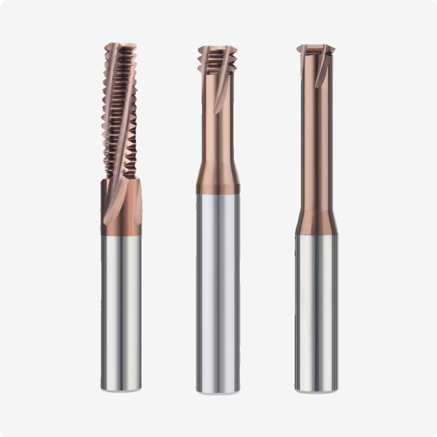
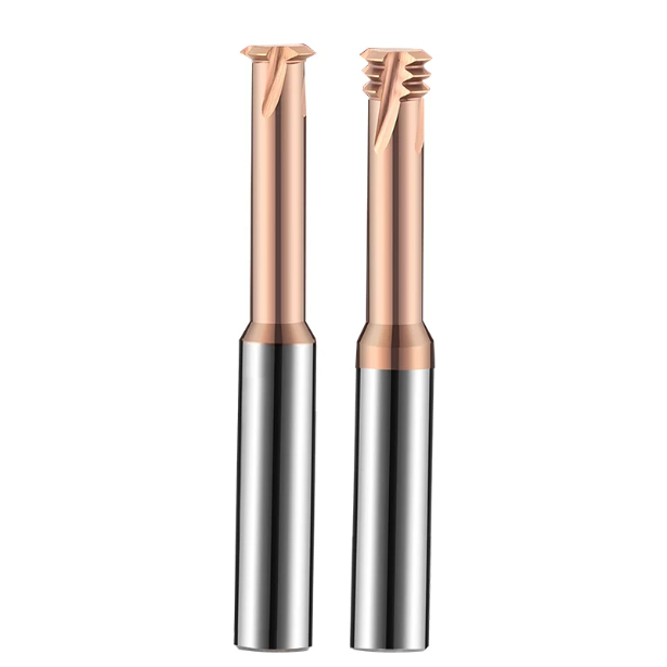
Manufacturing reliable hrc65 carbide thread milling cutters requires balancing substrate toughness, edge prep, and PVD coating performance. Achieving this demands 5-axis CNC grinding precision with tight runout tolerances, along with a dedicated sub-micron grain structure. Without optimized micro-geometry engineered directly into the tooth profile, even the most advanced helical toolpath will snap the tool.
Sub-Micron Carbide Substrates and Negative Rake Geometries for 60+ HRC
We avoid chasing raw substrate hardness alone, focusing instead on fracture toughness. For steels harder than 60 HRC, we grind our tools from ultra-fine sub-micron rods (0.4–0.6 µm grain size) with 8%–10% cobalt content. This fine grain structure arrests micro-crack propagation during high-frequency interrupted cuts, forming a strong initial defense against edge chipping in every carbide thread milling cutter.
For cutting geometry, we ditch positive rake designs for a negative rake (-3° to -6°) paired with a 0.015–0.025 mm negative T-land chamfer. This micro-chamfer shifts severe shear loads rearward into the solid carbide tooth body, converting dangerous bending tension into stable triaxial compression. This structural reinforcement is what keeps the tool cutting smoothly when engaging a 62 HRC blind hole.
High-Temperature AlTiN/AlCrN PVD Coatings to Resist Edge Breakdown
In hard milling, thin chips and high shear deformation frequently drive contact zone flash temperatures above 900°C. Raw carbide will quickly succumb to chemical crater wear and oxidation under these conditions. We apply high-aluminum nanolayered AlTiN or AlCrN PVD coatings, which develop a self-healing, dense aluminum oxide (Al₂O₃) protective film that acts as an effective thermal shield.
However, thicker coatings are not the answer for thread milling cutters for hardened steel. Excessive coating thickness rounds the cutting edge radius, dramatically increasing tool pressure and deflection. We hold our PVD thickness strictly to 1.8–2.5 microns, maintaining oxidation resistance near 1,000°C while keeping the honed cutting edge within a crisp 4–6 micron window.
Practical Shop-Floor Rules for Thread Milling Hardened Mold Cores
A premium tool solves only half the equation; the rest comes down to shop-floor execution. Above 50 HRC, machine controls instantly penalize the slightest programming oversight. Minor entry shocks or slight radial deflection—forgiving in mild steels—quickly escalate into piercing tool chatter, out-of-tolerance pitch diameters, or chipped cutting edges in hardened mold blocks.
Standardizing cutting paths for every thread mill cutter builds a reliable safety envelope for your spindle and workpiece. High-hardness machining leaves no room for guesswork. From smooth tangential roll-ins to staged depths of cut and internal arc feed adjustments, following hard-milling physics is what delivers repeatable tool life and zero scrap.
Arc-In and Arc-Out Toolpaths: Eliminating Dwell Marks and Premature Chipping
When troubleshooting edge chipping in hardened dies, we inspect the entry code before touching cutting speeds. The most destructive habit is driving a thread milling cutter tool straight in radially, cutting 360 degrees, and retracting along the same axis. Above 55 HRC, that abrupt radial plunge spikes cutting pressure instantly and leaves severe dwell marks on the thread flank.
Programmers must always apply smooth 90° or 180° helical roll-in and roll-out toolpaths. Sweeping the tool in along a gentle arc ramps chip thickness smoothly from zero to the target chip load. This completely eliminates mechanical shock, protects delicate micro-chamfers from snapping, and produces clean, mirror-like thread flanks without stress risers.
Multi-Pass Radial Infeed Strategy for Deep-Hole Thread Milling in Hardened Steel
When thread depths exceed 2.5D, tool deflection becomes your primary hurdle. Cutting the full thread profile in a single radial pass in 55+ HRC steel leads to classic taper errors: the pitch diameter narrows toward the bottom, causing the Go gage to bind while the No-Go spins right through. Heavier single cuts only trigger deflection and severe chatter.
We enforce a multi-pass radial infeed routine when thread milling hardened steel. In 58 HRC tool steel, run three progressive passes: take 65% of the radial depth on the rougher, clean up 25% on the semi-finisher to remove taper, and take a 10% spring pass to finish. This staged approach unloads the tool shank and locks deep-hole pitch diameters on size.
The Dynamic Feed Compensation Rule: Why Your CAM Pitch Feed Is Cracking the Cutter
This hidden trap catches even seasoned CNC programmers. When setting a chip load like 0.04 mm/tooth for internal threads, CAM software outputs an F-value along the tool center path. Because the center path circle is much smaller than the cutting edge periphery, the actual chip load at the bore wall spikes dramatically if internal arc compensation is inactive.
This geometric distortion is why a new carbide thread milling cutter can shatter seconds into the cut. The smaller the hole and the closer the tool diameter is to the bore, the worse the overfeed becomes. Always activate internal arc feed reduction in your CNC control, or manually scale the linear feed down to keep edge chip loads within safe limits.
When Off-the-Shelf Fails: Deploying Custom Carbide Thread Milling Cutters
Standard tool catalogs often hit a dead end on complex mold builds. Off-the-shelf tools are designed around general tolerances and wide-open clearances. Real mold components rarely offer ideal access: compact slide cores, dense water-line counterbores, and angled lifters routinely box the tool into tight, zero-clearance pockets.
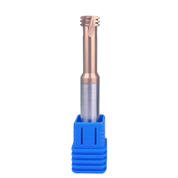
Forcing standard tools into extreme cavities drives up hidden scrap rates. When tackling deep non-standard threads or blind holes with zero relief, switching to custom carbide thread milling cutters is practical risk mitigation. Redesigning neck clearance, core thickness, and flute geometry for specific part geometry eliminates dwell marks, deflection, and unexpected tool breakage.
Solving Short-Pitch and Zero-Clearance Blind Holes with Custom Carbide Thread Milling Cutters
We ran into this scenario supporting a European automotive mold shop on an S136 core (54 HRC). The thread ended right against an internal cooling jacket, leaving less than 0.8 mm of axial clearance. Standard thread mills had lead-in chamfers that bottomed out before hitting full thread depth, while forcing Z travel lower risked crashing the flat tip into the floor.
Our team engineered a dedicated single-tooth, flat-bottom custom carbide thread milling cutters design with an enlarged core diameter. By eliminating front pilot dead-space and micro-dishing the tip, the tool cut full-depth threads within 0.2 mm of the blind bottom. If tight axial limits or zero relief grooves are stalling your shop, moving to a rigid, short-flute custom tool eliminates manual hand-chasing.
Form Tool Integration: Combining Chamfering and Threading in One Rigid Thread Milling Cutter Tool
Every extra tool change on 50+ HRC steel introduces runout stack-up and cycle delays. Running a spot drill for the chamfer followed by a thread mill often leaves subtle steps or secondary burrs due to micron-level spindle indexing errors. In high-pressure injection molds, these tiny flaws compromise critical O-ring sealing surfaces.
Integrating both operations into a single thread milling cutter tool solves the problem. Grinding a precise 45° or 60° chamfer tooth behind the thread flutes lets you finish the top bevel and thread the hole in one uninterrupted helical move. If multiple tool offsets are causing datum drift or cycle bottlenecks, combining the profiles locks down concentricity and eliminates machine positioning errors.
Machining H13, D2, and S136 requires balancing thermal shocks, abrasive wear, and work-hardening. Every setup differs in clamping rigidity, spindle power, and coolant pressure. If your shop is battling premature edge wear or tapered threads on complex mold drawings, reach out with your material hardness, hole depths, and CAD models. We will review the blueprints together to dial in a stable, chip-controlled cutting process.






