
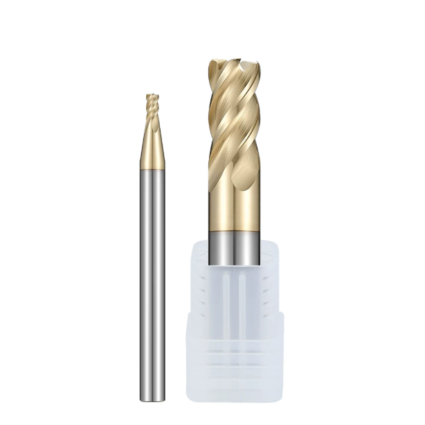
Last month, we assisted a North American aerospace facility troubleshooting a tough Ti-6Al-4V deep-slot job on a 5-axis mill. Less than twenty minutes after spindle start, the operator heard two sharp, piercing screeches. We immediately stopped the cut and pulled the tool: a deep, V-shaped notch had formed right at the depth-of-cut line, followed by a 0.3 mm fracture across the corner radius.
This combination of notch wear and micro-chipping is the single most common failure we see when helping shops optimize their milling cutters for titanium. Operators often react by dialing back cutting speed or switching to harder grades. Unfortunately, that usually backfires by creating more friction, trapping severe heat at the tip, and causing costly solid carbide tools to fail prematurely.
Titanium alloys feature extremely low thermal conductivity, high elasticity, and intense work hardening. They simply cannot be machined with standard steel strategies. Solving premature tool failure requires a systematic review of three critical areas:
- Edge micro-geometry: Are micro-chamfers and edge hones properly matched to the material? Do variable-helix flutes actively cancel cutting resonance?
- Toolpath engagement: Does your CAM strategy prevent sudden radial load spikes during corner transitions?
- Tool type and reach: Are you running rigid long neck bull nose end mill tools or targeted corner radii to distribute mechanical load across deep pockets?
Scrapped titanium billets and unscheduled downtime cost far more than cutting tools ever will. When tackling Grade 5 titanium, does unexpected notch wear frequently disrupt your cycle times?
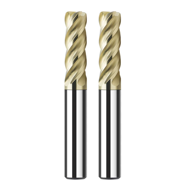
Why are milling cutters for titanium so prone to notch wear and tip chipping?
If you regularly monitor roughing operations on titanium structural parts, you know that tools rarely fail from uniform flank wear alone. Instead, failure usually begins when a localized groove tears into the depth-of-cut line, or a corner radius chips away unexpectedly. This premature breakdown in milling cutters for titanium is the direct result of extreme cutting physics clashing with the mechanical limits of cemented carbide.
Many programmers mistakenly apply stainless steel or tool steel parameters to titanium alloys. Titanium’s thermal conductivity is exceptionally low—roughly one-sixth that of medium-carbon steel—so cutting heat cannot escape through the chips. Temperatures at the cutting zone rapidly exceed 800°C. Combined with titanium’s high spring-back elasticity, severe shear stress and friction concentrate directly onto a microscopic section of the edge.
Understanding the Ti-6Al-4V work-hardened layer: Microscopic causes of notch wear at the depth-of-cut (DOC) line
During a recent failure analysis on tools returned from a medical bone plate line, we observed a classic wear pattern under the microscope. While the primary flute showed minimal wear under 0.08 mm, a jagged 0.25 mm V-notch had carved into the axial depth-of-cut line. This damage is driven by the abrasive outer scale of Ti-6Al-4V forgings and the work-hardened boundary left by previous machining passes.
During continuous engagement, the cutting edge strikes this hardened boundary with every revolution. Meanwhile, hot chips evacuate across this junction, reacting with ambient oxygen and nitrogen to accelerate chemical and mechanical abrasive wear. Simply thickening the PVD coating will not solve this; without breaking up the fixed contact point along the depth-of-cut line, notch wear will quickly lead to tooth breakage.
High Cutting Heat and Stress Concentration at the Tool Tip: Analysis of Conditions Causing Instantaneous Micro-chipping in Solid Carbide Milling Cutters
The tool-chip contact length is exceptionally short when milling titanium—often half that of carbon steel. This concentrates immense shear force and high thermal energy within 0.2 mm of the cutting edge. Under these conditions, the cobalt binder phase in solid carbide milling cutters quickly softens, triggering severe thermal-mechanical fatigue and micro-cracking across the edge.
If standard flood coolant fails to reach the cut consistently, rapid thermal cycling induces thermal shock cracks perpendicular to the cutting edge. Normal cutting resistance fluctuations then propagate these cracks until the corner chips away. In our field experience, controlling heat build-up and lowering localized tip pressure always takes priority over pushing heavy radial cuts.
Sudden Load Spikes and Over-cutting Impact: The Direct Influence of CAM Toolpaths on Micro-chipping of Titanium End Mills
When diagnosing edge chipping, many shops immediately blame the carbide grade. However, in our field audits across hundreds of machine shops, over 40% of chipping issues stem directly from basic CAM toolpath errors. When a tool drives straight into an internal corner, the radial engagement angle instantly spikes from 40 degrees to well over 180 degrees.
This sudden spike creates a severe shock load on any titanium end mill cutter, causing instantaneous tool deflection and high-frequency chatter. As the machine servos struggle with the load change, the resulting chatter chips the thinned cutting edge. We always recommend adding corner fillet smoothing or dynamic trochoidal motion rather than letting tools crash into sharp internal corners.
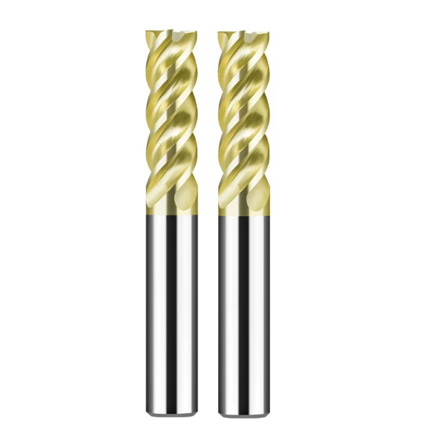
Geometric Edge Optimization to Prevent Chipping in Carbide Round Nose End Mills vs Flat End Mills
When troubleshooting edge chipping in titanium, we start by examining both macro-geometry and edge preparation. On flat-bottom end mills, the sharp 90-degree outer corner is inherently weak due to minimal backing carbide and severe thermal concentration. Upgrading to carbide round nose end mills introduces a continuous radius that redistributes cutting forces and dramatically reduces localized stress.
However, changing external geometry alone will not solve chipping. Tool engineers must balance micro-edge honing, rake angles, and core thickness. An overly sharp edge fractures under load, while excessive rounding causes severe rubbing and work hardening. Finding the sweet spot between sharpness and structural support is essential for stable production.
Dispersing Thermal Stress at the Tip via Round-Nose Geometry: Real-World Impact Resistance of Carbide Round Nose End Mills in Aerospace Structural Components
During a recent test on Ti-6Al-4V aerospace casing pockets, standard flat-bottom tools chipped at the corners after only 12 minutes. Switching to carbide round nose end mills with an R1.0 corner radius extended tool life past 45 minutes under identical cutting speeds and feed rates. The radial arc smoothly spreads cutting forces, drastically cutting down thermo-mechanical shock per unit area.
The corner radius also produces natural radial chip thinning. Chips curl and clear the pocket smoothly instead of packing and folding tightly in sharp corners. Where part blueprints allow, we always recommend replacing sharp corners with an R0.5 to R2.0 radius to eliminate premature tip failure during medium-to-heavy side milling.
Edge Honing and Micro-Chamfering Parameters: Standard Practices to Prevent Edge Chipping in Solid Carbide Slot Milling
Under high magnification, an un-honed carbide cutting edge reveals a jagged row of micro-serrations. In titanium slotting, these micro-teeth break off immediately, triggering rapid edge failure. When manufacturing solid carbide milling cutters for difficult alloys, we apply controlled CNC honing to maintain an edge radius between 12 µm and 18 µm, combined with a 2° to 4° negative micro-chamfer.
This edge preparation reinforces the carbide substrate against heavy shear loads without adding excessive tool pressure. While some operators fear honing increases cutting resistance, eliminating micro-crack initiation points far outweighs minor force increases. Protecting edge integrity in tough titanium cuts is always the top priority.
Unequal Pitch and Variable Helix Design: Eliminating Chatter and Chipping Caused by High-Frequency Resonance in CNC Milling Tools for Titanium
Titanium’s low modulus of elasticity easily triggers severe chatter when tooth pass frequencies match machine harmonics. To break these resonant frequencies at the source, our high-performance CNC milling tools for titanium feature unequal flute indexing combined with variable helix angles (such as 38°/41°).
Unequal flute spacing disrupts the harmonic timing between successive tooth impacts, while the variable helix shifts the cutting phase continuously along the axial depth. This geometry dampens chatter before it can build, transforming harsh cutting squeals into a steady hum and preventing harmonic chipping on tall sidewalls.
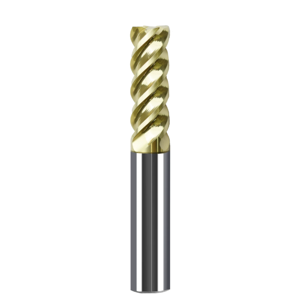
Deep Cavity and Narrow Clearance Conditions: Vibration Control and Tool Breakage Prevention for Long Neck Bull Nose End Mills
Deep-cavity titanium components like blisks and housings demand extended reach where clearance is tight. When overhang exceeds 4xD to 6xD, bending stiffness drops sharply, leaving standard tools prone to deflection. Running a long neck bull nose end mill clears side walls effectively, but the relieved neck creates a localized bending zone that requires strict deflection control.
Simply backing off the feed rate often backfires, causing the tool to rub and work-harden the flexible titanium wall. Successful deep-reach milling requires balancing neck overhang ratios, rigid toolholding, and adaptive toolpaths to keep tool deflection and harmonic vibration within tight, predictable limits.
Deflection and Micro-Vibration in Long-Overhang Machining: Preventing Premature Fatigue Failure at the Neck-Shank Junction of Long-Neck Bull-Nose End Mills
Investigating tool failures at an aerospace supplier revealed that most breakages occurred directly at the neck-to-shank transition radius. Scanning electron microscopy confirmed high-cycle fatigue beach marks caused by continuous alternating bending loads on the long neck bull nose end mill during deep pocketing passes.
To stop fatigue failures, we blend and polish the neck transition zone to eliminate microscopic grinding stress risers. Where wall draft angles permit, we switch from straight necks to tapered necks. Even a modest 1° to 1.5° taper increases the cross-sectional moment of inertia by over 30%, drastically cutting deflection and preventing brittle neck fractures.
Varying DOC and Trochoidal Side Milling Strategies: Distributing Wear Along the Long-Neck Bull-Nose End Mill
Milling deep slots at a fixed axial depth of cut concentrates abrasive work-hardened titanium right at the DOC line. This creates heavy localized notch wear that rapidly compromises the flute strength of your long neck bull nose end mill and triggers sudden corner breakage.
We prevent this by programming a dynamic trochoidal path with varying axial depths of cut. Shifting the DOC slightly on every pass spreads the depth-of-cut line wear across the flutes, preventing deep notches from forming while keeping radial tool engagement light, constant, and chatter-free.
Shrink-Fit Holders and High-Rigidity Clamping: Reducing Radial Runout to Under 3 µm in Deep Titanium Slot Milling
Long overhangs multiply spindle runout errors directly at the tool tip: 5 µm of runout at the holder nose can easily exceed 15 µm at 6xD overhang. When cutting tough titanium alloys, excessive dynamic runout forces a single flute to carry the entire chip load, causing catastrophic tip chipping upon initial entry.
We strongly advise replacing standard collet chucks with high-rigidity shrink-fit or precision hydraulic toolholders. These systems maintain total dynamic runout under 3 µm. Equal chip load across all flutes prevents single-tooth overloading and allows your titanium end mill cutter to achieve predictable, long-lasting tool life in demanding deep cavities.
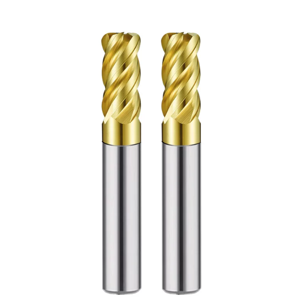
On-Site Machining Parameter Adjustment: Practical Rules for Extending the Life of CNC Milling Tools for Titanium
When troubleshooting cutting issues, machinists often drop the feed override at the first sign of noise. While backing off the feed protects cutters in aluminum or mild steel, doing so in titanium accelerates edge breakdown. Low thermal conductivity and strong elasticity require parameters that balance mechanical shear forces and thermal dissipation in the cut.
To get the full potential from CNC milling tools for titanium, you must maintain a stable, continuous shearing action. This balance depends on surface speed, feed per tooth, and proper coolant penetration through the thermal barrier. Real-world parameter tuning is not about copying catalog charts—it is a dynamic balance between chip evacuation and tool life based on machine rigidity.
The Bottom Line for Feed Rate and Feed Per Tooth (Fz): Preventing Titanium End Mill Cutters from Rubbing and Slipping in the Work-Hardened Layer
A frequent mistake on the shop floor is running feed rates below 0.01 mm per tooth. Titanium creates a 0.01 mm to 0.03 mm work-hardened skin under plastic deformation. If the feed rate of your titanium end mill cutter drops below this threshold, the edge rubs against the hardened layer instead of shearing, causing instant thermal ablation and flank wear.
We enforce a strict minimum chip load rule: the tooth must bite past the work-hardened boundary. Keep finish side-milling at a minimum of 0.035 mm per tooth, and roughing between 0.06 mm and 0.12 mm adjusted for chip thinning. Positive chip formation carries heat away in the chip and prevents catastrophic edge micro-chipping.
Dynamic Milling and Tool Engagement Angle (TEA) Control: Minimizing Mechanical Impact on Milling Cutters for Titanium
Full-slotting cuts subject carbide tooling to a punishing 180-degree engagement arc, leading to rapid mechanical shock and micro-fractures. When optimizing titanium roughing, we prioritize high cutting speeds and deep axial cuts paired with light radial engagement (Ae at 5% to 10% of tool diameter). This strategy keeps your milling cutter for titanium at a constant, low tool engagement angle.
Light radial cuts trigger radial chip thinning, lowering radial deflection forces on the tool shank. Shorter cut duration per revolution means less heat transfers into the tool body, allowing high-speed chips to carry thermal energy away. Steady cutting resistance eliminates cyclical load spikes, effectively stopping depth-of-cut notch wear before it starts.
High-Pressure Coolant and Chip Flushing: Eliminating Premature Titanium End Mill Failure Caused by Chip Re-cutting
Titanium chips are tough, stringy, and chemically reactive at elevated temperatures. Standard flood coolant often vaporizes before reaching the cutting zone, creating a vapor barrier that leads to localized dry cutting. Trapped chips dragged back through the pocket will instantly shatter the corner radius or flutes of your titanium end mill cutter.
We strongly recommend high-pressure through-spindle coolant running between 20 bar and 70 bar. High-pressure jets penetrate the vapor barrier directly at the tool tip for instant cooling. The focused hydraulic stream blasts chips out of the cutting zone within microseconds, preventing recutting and preserving the integrity of the cutting edge.
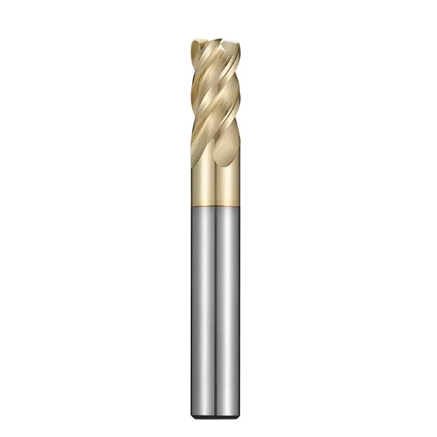
Cost-Reduction Solutions When Standard Tools Fail: Developing and Selecting Custom OEM Milling Cutters
When baseline feed adjustments, optimized toolpaths, and high-pressure coolant reach their limits, standard catalog tools become the bottleneck. Off-the-shelf cutters make design compromises in substrate toughness and rake geometry to handle mixed materials. In high-volume production, engineered OEM milling cutters eliminate premature wear by targeting the exact failure modes of your specific setup.
Custom tooling delivers unmatched process stability. If you face deep cavities, thin structural walls, or persistent notch wear, standard geometries will hold back your cycle times. If you are struggling with severe part deflection or high scrap rates, then you can review specialized transition tapers and engineered corner profiles to reduce overall cost per part.
Matching Substrate Grades with Nano-Coatings: Balancing Hardness and Toughness in OEM Milling Cutters for Specific Titanium Alloys
Chasing extreme hardness often leads to brittle edge failure during interrupted cuts. When engineering custom OEM milling cutters, we balance micro-grain hardness against transverse rupture strength. Grade 2 titanium demands razor-sharp ground edges with anti-stick coatings, while Ti-6Al-4V forgings require tough sub-micron substrates with higher cobalt content to handle heavy mechanical shock.
PVD coatings must provide both extreme wear resistance and a thermal barrier against titanium adhesion. We apply silicon-doped nanolayer coatings (like TiAlSiN or AlCrSiN) that resist oxidation past 1100°C. If you are experiencing edge flaking from intense thermal cycles, then you can upgrade to heat-blocking nanocoatings to stop thermal cracks from spreading into the carbide substrate.
Specialized Chip Breakers and Non-Standard Corner Radius Optimization: How OEM Milling Cutters Reduce Cost Per Part
In high-volume aerospace machining, cost per finished part matters far more than the initial tool price. Standard end mills with fixed radii often leave excess stock, requiring extra clean-up passes in deep pockets. With dedicated OEM milling cutters, we grind application-specific corner radii (like R1.25 or R2.35) directly onto the tool to combine roughing and semi-finishing steps.
Adding engineered chip-breaker serrations along the rake face breaks tough titanium ribbons into small, manageable segments. This prevents chip packing in deep ribs and stops chips from scoring finished surfaces. If you are losing time to manual chip clearing, then you can consolidate operations with dedicated chip-breaking profiles to cut cycle times significantly.
Determining Tool Change Benchmarks for Batch Titanium Machining: Establishing Scientific Early-Warning Standards for CNC Milling Tools for Titanium
Waiting for cutting squeals or catastrophic breakage before changing tools guarantees scrapped titanium parts and potential spindle damage. In production lines running CNC milling tools for titanium, process control requires strict, quantifiable wear limits. We recommend setting mandatory tool retirement thresholds: maximum flank wear (VB) under 0.15 mm and notch wear depth (VBN) under 0.20 mm.
Combine spindle load monitoring with routine benchtop optical inspection to track wear progression accurately. If you are building automated machining cells for titanium, then you can set tool change cycles based on proven part counts rather than running cutters to the edge of fatigue failure.
If you are currently battling depth-of-cut notch wear, chatter on long-reach tools, or premature chipping on complex titanium components, feel free to reach out with your part prints, alloy grades, and machine data so we can evaluate your setup and dial in the right tool geometry.






