
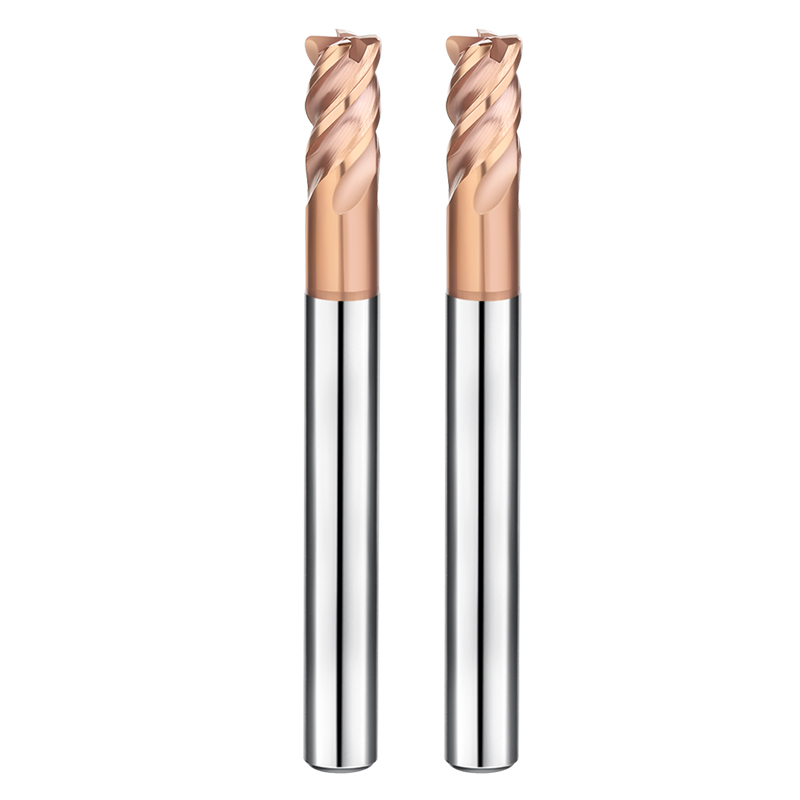
A few months ago, while helping an automotive mold shop in Ohio optimize cycle times, we ran into a classic machining bottleneck. To meet a tight deadline, the operator tried full-slotting deep channels in 4140 pre-hardened steel (HRC 32–35) on an older BT40 vertical machining center. Spindle load instantly spiked past 110%. After just three parts, the 4 flutes roughing end mill suffered edge micro-chipping from chip packing and thermal shock, forcing an immediate feed rate override.
We see this scenario play out almost weekly across machine shops in the US and Europe. When roughing steel, programmers often debate between two paths: run direct linear slotting with a knuckle-profile tool, or switch to dynamic trochoidal milling in CAM?
Theoretical formulas rarely account for real machine limits. Can your spindle torque handle 100% radial engagement? Will your CNC controller stutter during rapid directional changes? Beyond machine dynamics, core rigidity, chip gullet capacity, and the actual strategy for calculating roughing end mill feeds and speeds differ drastically between these two methods.
Choosing the wrong toolpath wastes the high heat resistance of carbide roughing end mills on air passes and thermal fatigue, or overloads your spindle bearings. When roughing 4140 or P20 mold steel, are you pushing machine rigidity to the edge with full-slotting, or letting the cutter fly along a dynamic path to save tool life?
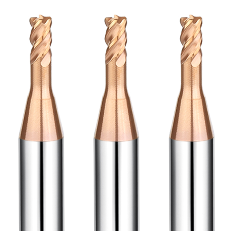
The Limits of Traditional Full Slotting: When a 4-Flute Roughing End Mill Is Essential
Many programmers default to dynamic toolpaths the moment they see a slot. However, for shallow features, short machine travels, or high-torque spindles, straight-line slotting remains indispensable. In these setups, forcing a trochoidal path increases cycle times due to air passes and axis deceleration.
Still, full-slotting steel pushes tooling to its physical limits. With a 180-degree radial engagement, heat and cutting forces concentrate directly at the flute core. Standard flat end mills often fail from thermal shock past 0.75D depth of cut. In contrast, a purpose-built roughing end mill for steel uses specialized flute geometry to split these high mechanical loads.
Torsional Breakage Resistance and Chip Control with 4 Flutes Roughing End Mills in Rigid Machines and Heavy-Duty Slotting
We recently helped a German supplier mill keyways in 4340 transmission shafts on a rigid BT50 horizontal mill. They initially ran 3-flute cutters but faced recurring tool breakage from chip packing deep inside the pocket. While fewer flutes provide larger chip pockets, a 3-flute tool has a smaller core diameter that struggles against heavy torque spikes.
Switching to a 4 flutes roughing end mill with an enlarged core boosted torsional strength by nearly 30%. The sinusoidal wave-edge profile breaks stringy steel chips into compact, C-shaped segments. These small fragments evacuate quickly through the rotating flutes, eliminating catastrophic breakage caused by chip recutting.
Feed and Speed Limits for Roughing End Mills in Full-Slot Milling (Based on Tests with 4140/P20 Steel)
In our testing facility, we have mapped out clear cutting boundaries for quenched 4140 (HRC 30–34) and pre-hardened P20 mold steels. Many machinists run overly conservative feeds out of caution. Unfortunately, feeding too light causes the cutting edge to rub against work-hardened layers, rapidly degrading the coating.
To get the most out of your setup, keep roughing end mill feeds and speeds within a stable load window. We run surface speeds between 80 and 110 m/min (260–360 SFM) to manage heat, while maintaining chip loads between 0.04 and 0.08 mm/tooth (0.0015–0.003 IPT) on a 1/2″ tool. Paired with strong air blast, heat exits with the chips rather than soaking into the tool.
Shop-Floor Insights on Suppressing Slot-Milling Chatter with Serrated-Edge Roughing End Mills in Short-Overhang Setups
When your setup allows short tool overhang—under 3x diameter (3D) held in a hydraulic chuck or shrink-fit holder—full-slotting is highly productive. Under high clamping rigidity, the main issue shifts from tool deflection to high-frequency harmonic chatter.
This is where serrated-edge roughing end mill cutters make a noticeable difference. The offset crests along the flutes disrupt cutting force resonance, converting continuous heavy shear into micro-interrupted cuts. On the floor, the loud high-pitch screech drops to a controlled hum, protecting spindle bearings and eliminating heavy wall chatter.
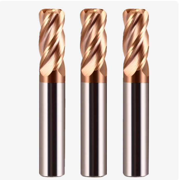
Practical Application of Trochoidal and Dynamic Milling: Optimal Conditions for Carbide Roughing End Mills
If your job involves roughing deep cavities, clearing narrow slots, or running on a 40-taper machine with limited rigidity, dynamic milling is a game-changer. In shops across the US and Europe, we often see machinists struggle with low spindle torque during full-slotting, which causes intense vibration. Switching to a constant-engagement trochoidal path drastically lowers cutting forces and eliminates tool chatter.
In this strategy, cutting relies on high surface speeds and light step-overs (Ae around 5% to 15% of tool diameter). Here, carbide roughing end mills fully leverage their hot hardness and abrasion resistance. Because edge engagement is brief and the radial wrap angle stays constant, the cutter avoids heavy shock loads. This lets you ramp up spindle RPM and achieve high metal removal rates without stalling.
Tool Wear Patterns in High-Depth-of-Cut (High Ap, Low Ae) Milling with Solid Carbide Roughing End Mills
Traditional heavy-duty milling tends to concentrate wear on the bottom corner and leading tip. The first few millimeters often chip while the rest of the flute stays untouched, wasting tool potential. When roughing deep mold steels, we set the axial depth (Ap) to 2D or 3D while significantly reducing radial engagement (Ae), distributing the cutting load evenly across the entire flute length.
Running this approach with solid carbide roughing end mills produces a stable and predictable wear pattern. The side cutting edges exhibit uniform micro-flank wear from top to bottom, with virtually no cratering or thermal cracking. This wear behavior prevents sudden tool breakage and helps programmers accurately predict tool life during lights-out machining.
Optimizing Roughing End Mill Feeds and Speeds for Dynamic Milling Paths to Prevent Heat Accumulation When Cutting Steel
Machinists new to dynamic milling often make one critical mistake: seeing tiny step-overs, they hesitate to increase the feed rate. This causes the chips to become too thin to carry away heat, leading to rapid edge annealing. With small radial step-overs, chip thinning occurs; you must aggressively boost chip load so the flutes shear metal cleanly instead of rubbing the work-hardened surface.
Our shop rule for roughing end mill feeds and speeds in dynamic paths is simple: run high surface speeds and push the feed per tooth. Surface speeds can reach 150 to 220 m/min (500–720 SFM), with table feeds 2 to 3 times higher than slotting values. The brief contact time expels heat through flying chips, and an air blast keeps the workpiece and tool body cool.
Why Not All Trochoidal Paths Require High-Flute Finishing Cutters: The Chip Control Advantages of Roughing End Mills with Wavy Edges
Running 5-flute or 7-flute smooth end mills in dynamic milling is popular for open, shallow cavities with uniform stock. However, in deep cavities or enclosed pockets, smooth-flute cutters create long, continuous ribbons of metal that bird-nest at the bottom. When recut, these trapped chips instantly snap high-flute cutters that lack generous chip gullets.
This is where knuckle-profile end mills for roughing remain essential. The wavy profile chops long, stringy chips into short, discrete segments. Even in pockets as deep as 4D, high-pressure air easily evacuates these compact chips. For reliable, unmanned roughing operations, positive chip evacuation matters far more than part surface finish.
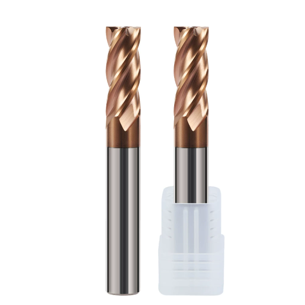
Matching Tool Geometry and Material: Selection Criteria for Milling Steel
Discussing cutter geometry or carbide grades without looking at the programmed toolpath rarely delivers maximum efficiency. Different toolpaths create completely different mechanical stresses on the tool body. Heavy full-slotting demands extreme toughness to survive shock loads, while high-speed trochoidal milling depends on high hot hardness and wear resistance.
When machining 4140 pre-hardened steel or NAK80 mold steel, first evaluate machine spindle power and fixture rigidity. For slotting, tool core stiffness sets your operating ceiling; for dynamic paths, helix angles and micro-honing control chip flow. Understanding these mechanics is vital when selecting a roughing end mill for steel.
Balancing Chip Gullet Volume and Core Strength in 4-Flute Roughing End Mills for Full-Slot and Trochoidal Milling
Machinists often face a tough tradeoff: a thicker core provides high bending stiffness but shrinks chip pockets, while a thinner core aids chip clearance but risks tool deflection. In our CNC grinding production standards, the 4-flute configuration is the proven benchmark for steel roughing because it balances core cross-section with adequate flute volume.
During full-slotting cuts, a 4 flutes roughing end mill built with a 58% to 62% core ratio easily handles heavy radial thrust forces. When switched to a dynamic path, the radial cut narrows, generating smaller individual chips. The 4-flute design still offers plenty of gullet clearance while allowing higher table feed rates thanks to its multiple cutting edges.
Coating Heat Resistance and Chipping Control for Carbide Roughing End Mills (Wave-Edge) Machining Hardened Steel (HRC 45–55)
When roughing hardened tool steels like D2 or SKD11 above HRC 45, instantaneous temperatures at the shear zone easily exceed 800°C. Standard TiAlN coatings oxidize rapidly under these conditions, and the cobalt binder can soften, triggering micro-chipping under intermittent cutting impacts.
For these hard-milling jobs, we recommend micro-grain (0.4–0.6 μm) carbide roughing end mills coated with high-aluminum TiAlSiN or AlCr-based films. The serrated profile breaks cutting forces into smaller contact points. Combined with controlled edge honing, this design prevents initial edge chipping and lets chips carry away the majority of the heat.
Residual Wave Height Considerations for Roughing End Mills When Transitioning to Slot or Trochoidal Milling
Programmers often encounter premature finishing tool failure or unexpected chipping when switching directly from roughing to finishing passes. This problem usually stems from ignoring the peak-to-valley wave profile left behind by the roughing cutter. While wave-edge cutters remove large volumes of stock, they leave noticeable scallops on sidewalls and pocket floors.
When using wave-profile roughing end mill cutters, your stock allowance per side must exceed the peak-to-valley depth (typically 0.3 to 0.5 mm), with a safe recommendation of 0.6 to 0.8 mm. Leaving too little stock forces the finishing tool to rub on work-hardened wave crests. Proper stock allowance ensures the finishing cutter engages solid base metal cleanly.
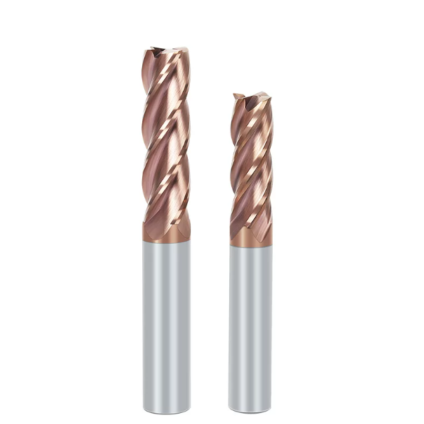
Real-World Case Study from Western Workshops: Strategic Decisions on End Mills for Roughing Based on Spindle Load and Per-Part Cost
While supporting overseas machine shops on-site, we often see a recurring pattern: shop supervisors focus solely on the purchase price of the cutting tool. They overlook hidden costs tied to excessive spindle loads, including higher energy bills, machine guideway wear, and frequent tool-change downtime. In reality, toolpath strategy and tooling selection directly drive ammeter spikes and part labor costs.
Roughing accounts for over 60% of the cycle time when machining tough materials like 4340 structural steel or large mold bases. Choosing between full-slotting and dynamic trochoidal paths cannot rely on theoretical guesswork. You must evaluate spindle torque curves, toolholder rigidity, and total cycle times. Using the right end mills for roughing alongside optimized toolpaths is the true driver of per-part cost reduction.
Case Study 1: Cost Reduction via Toolpath and Roughing End Mill for Steel Optimization on a BT40 Spindle
Last year, we assisted a Pennsylvania machinery shop milling gearbox slots in 4340 alloy steel (HRC 34–38). The programmer initially ran straight-flute end mills on a BT40 vertical mill for full-slotting at an 8 mm depth of cut. Spindle load meters frequently redlined past 115% with severe tool screech. Thermal fatigue chipped cutting tips every two parts, causing high scrap rates and downtime.
Addressing their machine’s limited low-end torque, we overhauled the process. We switched to a full-flute dynamic path (Ap 20 mm, Ae 8%) and loaded an application-specific roughing end mill for steel. Spindle load dropped to a stable 45%, cutting-zone heat dissipated smoothly, and single-tool life jumped from 2 to 18 parts, cutting total tooling and labor costs by 42%.
Case Study 2: Reducing Cycle Time by 35% in Deep-Cavity Mold Roughing Using Wave-Profile End Mills for Roughing
Another case involved an automotive mold shop in Monterrey, Mexico, roughing 45 mm deep pockets in P20 pre-hardened steel. Their original program used a conservative, step-down approach with smooth-flute cutters, taking 48 minutes per part. Chip evacuation was so poor that operators had to manually blow out chips, preventing lights-out automation.
We redesigned the path using adaptive helical entries with trochoidal clearing and introduced wave-edge end mills for roughing. The serrated flutes broke stringy chips into small, manageable curls that cleared the deep cavity easily. This allowed a 3x feed rate increase without chip packing, reducing cycle time to 31 minutes and enabling unattended overnight shifts.
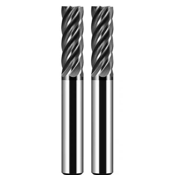
Machining Stability from the Factory Floor: Quality Standards at a China CNC Roughing End Mill Factory
Moving from machining strategies back to tool manufacturing reveals why cutting tools behave differently in the cut. Machinists often face batch-to-batch tool life inconsistency or sudden, unpredicted tool failure. These issues typically stem from carbide substrate variations and poorly managed grinding stress relief rather than programmer error.
As a dedicated china cnc roughing end mill factory, we know that microscopic manufacturing deviations cause massive swings in tool life under heavy loads. Manufacturing high-performance tools involves far more than grinding a wave profile; it requires precise substrate selection, 5-axis thermal stress management, and controlled micro-edge honing before and after coating.
Withstanding Harsh Slotting Impacts: How a China CNC Roughing End Mill Factory Controls Substrate Toughness and Edge Honing
During heavy full-slotting, tools face extreme shock loads and torsional shear stresses. When machinists report edge chipping on initial contact, the culprit is usually brittle carbide substrates or unhoned, razor-sharp grinding edges. Substrates must maintain high hardness while retaining enough fracture toughness to absorb continuous cutting shocks.
At our china cnc roughing end mill factory, we apply automated micro-blasting and drag finishing to hone wavy cutting edges into uniform 0.02–0.035 mm radial transitions. If you are slotting high-tensile 4140 or 4340 steel, choose cutters with controlled edge prep to prevent micro-chipping and carbide grain pullout during initial material entry.
Minimizing Deflection Errors in Dynamic Milling: Concentricity and Runout Control for Carbide Roughing End Mills
When running dynamic paths with long flute engagement, cutter deflection and uneven flute loading become the primary failure modes. If a tool’s Total Indicated Runout (TIR) exceeds 5 microns, only one or two flutes take the entire cutting load at high spindle speeds, causing wall taper errors and harmonic chatter.
When grinding our carbide roughing end mills, we use automated optical inspection and dynamic wheel balancing to hold concentricity and radial runout under 3 microns. If you are processing deep cavities in production and notice tapered sidewalls, check the combined runout of your holder assembly, as balanced cutting loads are essential for long-reach stability.






