
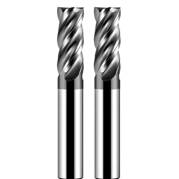
Over the past 15 years of helping machine shops across the US and Europe solve deep-pocket milling bottlenecks, the most frequent complaint we hear is severe chatter.
When cutting cavities deeper than 4xD, many machinists instinctively dial down the feed rate and spindle speed. Machining cycle times double, yet tool life plummets. The tool screams in the cut, and the cutting teeth fracture at the pocket floor, scrapping expensive pre-hardened mold steel in seconds.
This is not an isolated case. A precision mold shop in North America recently consulted us about roughing HRC55 P20 and NAK80 tool steel. Their 4-flute tools broke every couple of passes. The long stickout killed tool rigidity, and chip packing caused severe recutting—even with premium standard tools.
Deep-pocket milling cannot be solved simply by using an extra-long shank. Success requires balancing cutting forces across the overhang, engineering dedicated neck relief, using variable helix geometry to cancel harmonic vibration, and matching heat-resistant coatings to the workpiece.
As a manufacturing team dedicated to engineered end mill bits for metal, we developed these battle-tested strategies across hundreds of shop-floor setups. If you deal with tool runout, thermal fatigue, and micro-chipping during long-overhang jobs, these geometric tweaks and CAM strategies will stabilize your carbide end mill bits and maximize metal removal rates.
Are your current long-shank end mills for metal cutting cleanly and quietly, or are they rubbing and deflecting at the bottom of the cavity?
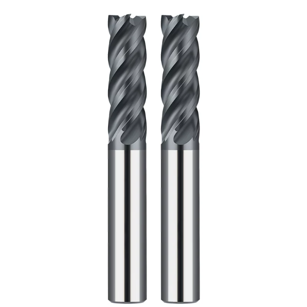
Why Do Deep Pocket Milling Operations Often Suffer from Chatter and Edge Chipping?
Deep cavities remain among the toughest operations on the shop floor. In our field diagnostics, over 70% of long-reach tool failures stem from a sudden loss of system rigidity rather than insufficient carbide hardness. When cutting forces cannot dissipate through a long tool assembly, elastic deflection quickly triggers harmonic resonance, forcing the cutting edge to bounce and hammer against the metal.
Many machinists try to fight chatter by lowering the spindle speed, but this often backfires. In our test cuts, dropping speed blindly shifts the tool into an unstable force zone, causing microscopic edge chipping under uneven cutting loads. Mastering deep-cavity work requires controlling dynamic deflection from the ground up, which is how we engineer our high-performance end mill bits for metal.
The Perilous L/D Ratio: When Long Shank Carbide End Mill Bits Lose Rigidity
In tool mechanics, the length-to-diameter (L/D) ratio acts as a force amplifier. Once tool stickout exceeds 4xD or reaches 8xD, bending rigidity drops at a cubic rate. Using dynamic strain gauges, we have measured how radial deflection on standard long-reach carbide end mill bits spikes rapidly, making edge stability almost impossible under traditional toolpaths.
This loss of rigidity also distorts load transfer into the machine spindle. As the flutes deflect, the primary clearance face rubs against the cut surface, generating intense localized heat. We resolved an issue for an aerospace supplier whose tools were snapping from fatigue caused by excessive radial bending rather than abrasive wear. Controlling radial cutting force is the single most important rule when running extended stickout.
Neck Relief Design: Preventing Chip Recutting in CNC Deep Pocket Machining
In enclosed pockets, trapped chips are lethal to cutting edges. Standard full-flute tools frequently choke because chips accumulate in tight sidewall gaps and get re-crushed by the spinning flutes. Microscopic analysis of broken tools often shows that edge chipping was triggered by chip recutting wedging metal between the flute and the pocket wall during CNC operations.
This is why we engineer targeted neck relief into every deep-pocket tool. By shortening the cutting flutes and reducing the neck diameter, we create an open evacuation path and eliminate wall friction. In an automotive mold trial, adding this relieved shank dropped cavity floor temperatures by nearly 15% and completely eliminated tool breakage caused by chip packing.
Rethinking Toolpaths: Redefining Machining Strategies for Deep Cavity End Mills for Metal
Applying handbook feeds and speeds to deep cavities is a fast route to broken tooling. Traditional heavy radial cuts (large Ae, shallow Ap) push forces sideways against the weakest axis of an extended tool. When optimizing customer setups, we replace these old routines with toolpaths designed specifically for long-reach end mills for metal.
We rely heavily on High-Efficiency Milling (HEM) strategies, setting radial width of cut (Ae) between 5% and 10% of tool diameter while taking deep axial steps (Ap) up to 2xD. This redirects cutting forces upward along the tool axis where compressive strength is highest. With this optimized dynamic path, long-shank tools stay rigid and quiet even at elevated table feeds.
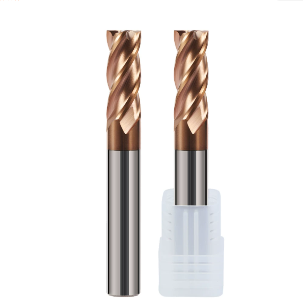
Deep Cavity Roughing and Corner Cleaning: How to Properly Use Carbide Square End Mills to Control Lateral Cutting Forces?
During deep-cavity roughing and corner cleanup, lateral cutting force acts as a silent killer on long-reach tools. Our shop-floor tests show that exceeding force limits causes microscopic tool deflection. This deflection quickly leads to stepped wall finishes, taper errors, or snapped cutters. When slotting or profiling deep sidewalls, keeping lateral push to a minimum is essential for part accuracy.
We often see machinists engage the entire flute length aggressively, treating long-reach tools like standard-length tooling. In deep pockets, this turns the tool shank into a flexible spring. The key to successful roughing with a carbide square end mill is managing the cutting edge engagement angle. Converting lateral forces into manageable axial loads keeps the tool cutting clean and flat at the bottom of the pocket.
Reducing Radial Depth of Cut (Ae) and Increasing Axial Depth (Ap): Toolpath Strategies to Enhance Rigidity in Metal Cutting End Mills
Traditional shallow axial cuts with heavy radial widths generate massive side loads that destroy long setups. For overhangs past 5xD, we always recommend a high-efficiency milling approach using low Ae and high Ap. Keeping radial stepover between 5% and 8% of the cutter diameter spreads heat and wear evenly across the entire flute, extending the working life of high-performance metal cutting end mills.
This toolpath setup dramatically shifts the direction of the primary cutting forces. With an ultra-thin radial chip thickness, side deflection drops, and the machine spindle absorbs forces axially along the tool body. When troubleshooting deep pockets for a German machinery builder, this strategy eliminated bottom-floor stepping while raising the metal removal rate by nearly 40%.
Corner Deceleration and Arc Entry/Exit: Preventing Instantaneous Chipping of Carbide Square End Mills in Sharp Corners
Straight linear moves into internal 90-degree corners are recipes for broken cutters. As the tool hits the corner, the radial engagement angle surges from 90 to 180 degrees, spiking cutting forces instantly. We have watched countless operators lose an expensive carbide square end mill because the tool jammed into a dead corner, leaving a severe gouge in the mold wall.
To prevent shock loading, you must optimize your CAM toolpaths for continuous motion. Never program straight plunge cuts into corners; always use arc roll-ins, roll-outs, and dedicated trochoidal cornering paths. Programming a 15% feed deceleration right before corner engagement gives the extended shank enough buffer time to absorb load spikes without chipping.
Variable Pitch and Variable Helix Geometry: Suppressing Resonance at the Source in Long-Shank End Mill Bits for Metal
A high-pitched squeal during a cut indicates the tool has entered harmonic resonance, which causes rapid edge micro-chipping. Standard mills with equal flute spacing hit the material at uniform time intervals, building up harmonic energy. To solve chatter mechanically, we developed specialized geometries for our long-reach end mill bits for metal.
By combining uneven flute indexing with variable helix angles, each cutting tooth enters the metal at a slightly offset phase angle. This design cancels shockwaves naturally from tooth to tooth, disrupting vibration before it builds up. Field data shows our anti-vibration geometry delivers three times the damping stability of standard tools at the same long reach without requiring specialty dampening tool holders.
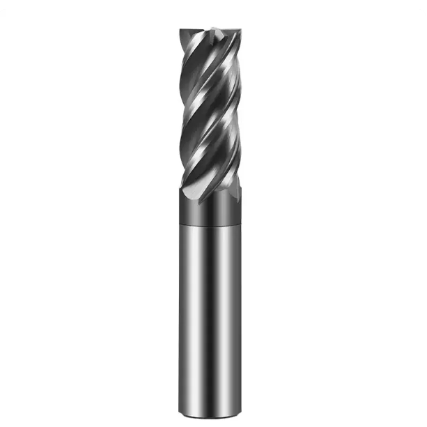
Mastering Deep-Cavity Machining of HRC55 Hardened Steel: Practical Strategies for Dry and Coolant-Assisted Cutting with Carbide HRC55 End Mills
Milling deep cavities in hardened steels (HRC55+ like SKD11, D2, and Caldie) pushes tool substrate and coating integrity to the limit. Shop-floor thermal testing confirms that over 70% of hard milling heat concentrates right at the cutting edge and chip interface. If this heat cannot escape via the chip, the extended carbide shank softens rapidly, causing immediate edge breakdown.
When helping mold shops troubleshoot hard milling, we notice many operators focus on surface finish while ignoring thermal shock cycles. Reliable hard milling requires premium carbide HRC55 end mills paired with a controlled thermal strategy. Managing cutting temperature gradients ensures predictable tool life and tight tolerances, even under deep-reach overhangs.
Coolant or High-Pressure Air Blast? Preventing Thermal Shock When Milling Deep Cavities with Carbide HRC55 End Mills
Flooding high-hardness steel cavities with liquid coolant is the leading cause of premature edge failure. As the cutting edge alternates between 800°C cuts and cold emulsion, rapid thermal cycling creates microscopic stress cracks in the tungsten carbide substrate. Operators often blame inadequate tool hardness when thermal shock was the real issue shattering the cutting edge.
We strongly advise cutting dry with high-pressure air (above 0.6 MPa) or Minimum Quantity Lubrication (MQL) when running carbide HRC55 end mills. Dry air cooling eliminates thermal shock while blasting glowing chips cleanly out of deep cavities to prevent recutting. Operators also gain clear visibility of the cut zone and chip color to monitor process stability.
Deep Cavity Milling in Mold Steel: Reducing Spindle Load on Long-Reach Carbide End Mill Bits via High-Feed Milling (HFM)
Heavy-depth roughing in mold steels over HRC50 creates excessive radial loads on long tool assemblies. To maintain high metal removal rates without overloading the spindle, we implement High-Feed Milling (HFM) techniques. This approach uses a low lead angle (10° to 15°) to thin the chip and direct cutting forces upward into the tool holder.
Running axial stepdowns (Ap) between 0.2 mm and 0.8 mm while raising feed per tooth (Fz) by 3x to 5x converts lateral forces into manageable axial thrust for long-reach carbide end mill bits. Implementing this strategy with an automotive mold maker lowered spindle loads by 35%, eliminated vibration, and turned a break-prone 6xD roughing job into a reliable unattended process.
Chamfering and Heat-Resistant Coating (TiSiN): Extending the Service Life of End Mills for Metal in Deep-Cavity Hard Milling
Micro-chipping during hard milling typically starts at the ultra-sharp, unsupported outer corners of the tool. Conventional sharp-cornered flutes break down easily against the hard inclusions in HRC55 steel. We add precision edge-honing and protective corner chamfers (or small corner radii) to reinforce the cutting edge against high-impact forces.
Coating choice is equally critical: standard TiAlN degrades past 800°C, whereas our silicon-doped nano-composite TiSiN coating handles oxidation temperatures up to 1100°C. This nanocomposite layer forms a dense thermal barrier that protects the carbide core from extreme heat. Combining protective edge prep with advanced TiSiN coating routinely doubles the working life of our end mills for metal in hardened deep cavities.
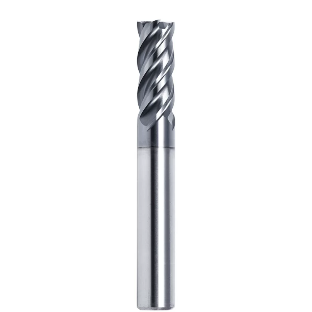
Toolholder Selection and Clamping Runout: The “Silent Killer” of Deep-Cavity Machining Often Overlooked by CNC Workshops
When troubleshooting deep-cavity failures, many workshops instinctively blame feeds, speeds, or carbide grades. In our 16 years of hands-on diagnostics, over half of all abnormal wear and edge-chipping cases trace back to toolholder clamping runout. When running long stickouts, even a tiny clamping eccentricity gets magnified into violent oscillations at the bottom of the cavity.
Many machinists assume standard ER collet chucks can handle every job. While acceptable for short tooling, standard collets are a gamble in deep-pocket milling due to limited clamping force and runout variance. Achieving consistent tool life requires pairing high-performance end mills for metal with high-precision toolholders, making rigid tool clamping just as critical as optimized flute geometry.
The Runout Amplification Effect: Why Runout for Long-Reach End Mills for Metal Must Be Kept Under 0.005mm
Runout degrades tool life exponentially as overhang increases. A radial runout of just 0.005mm at the holder nose can easily amplify to over 0.02mm at the tip when reach exceeds 5xD. This uneven runout forces one single flute to absorb the entire cutting impact, causing premature micro-chipping and catastrophic tool failure across the whole cutter.
Our laboratory cutting tests show that keeping tool-tip runout within 0.003mm to 0.005mm ensures smooth, uniform edge wear across all flutes. Once runout exceeds 0.01mm, tool life drops by more than 60%, leaving heavy chatter marks on sidewalls. When setting up high-precision jobs, we treat 0.005mm total indicator reading (TIR) as the absolute threshold for long-reach end mill bits for metal.
Performance Comparison: Shrink-Fit vs. High-Performance Hydraulic Tool Holders in Deep-Cavity CNC Milling
Choosing between shrink-fit and hydraulic holders is a common dilemma for deep-pocket work. In our field evaluations across complex CNC setups, shrink-fit holders offer unbeatable concentricity and a slim nose profile that reaches into deep cavities without interference. However, their clamping bores require strict shank tolerances, and clamping force gradually degrades over repeated heating cycles.
Hydraulic holders use internal fluid pressure to grip the shank uniformly, delivering exceptional vibration damping that absorbs cut harmonics. While their bulkier nose can cause clearance issues in tight pockets, they excel under heavy cuts. We typically advise clients to run shrink-fit for high-speed finishing walls and hydraulic holders for heavy roughing where damping chatter is paramount.
Short Clamping and Minimal Overhang: Our Standardized Tool Clamping Process
On the shop floor, operators often slide a long-reach tool into a holder without measuring the absolute minimum required stickout. Every extra 10mm of exposed shank significantly reduces bending stiffness and magnifies deflection. This casual setup habit remains a leading cause of premature chipping and high tooling scrap rates.
To eliminate this variable, we enforce a “minimal stickout” standard with our partner shops. We calculate the exact clearance envelope in CAM simulation, then set the tool gauge length on an optical presetter with at least 3xD shank engagement inside the bore. Standardizing this clamping procedure maximizes the native stiffness of your end mill bits for metal while cutting monthly tooling costs.
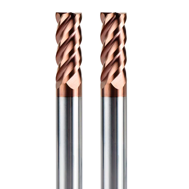
How to Evaluate Carbide End Mill Suppliers on Deep-Cavity Customization and Technical Support?
Deep-cavity milling is an integrated process where simply buying an off-the-shelf catalog cutter rarely solves the root issue. From managing high L/D bending forces and relief necks to dialing in HRC55 dry air blasts and zero-runout holders, every small detail matters. A supplier that merely ships part numbers cannot solve complex machining bottlenecks the way a process-driven manufacturer can.
Working with precision machine shops worldwide, we know that great toolmakers must master both carbide metallurgy and dynamic machine-tool mechanics. When evaluating reliable carbide end mill suppliers, look past their short-overhang test cuts. Focus instead on their ability to modify custom geometries rapidly and provide real CAM-level toolpath optimization for challenging setups.
How Top-Tier Carbide End Mill Suppliers Customize Neck Relief and Flute Length for Deep-Cavity Applications
Standard catalog end mills are built for general-purpose cuts. In pockets deeper than 5xD, standard tools either have flutes that are too long (causing flex) or lack neck relief (causing shank rub). If you are struggling with deep walls or tight floor radii, you should request a tailored tool geometry featuring shortened cutting flutes and a stepped-down relief neck.
Experienced carbide end mill suppliers should evaluate your part prints quickly and accurately. When vetting a vendor, notice if they proactively recommend adjustments to helix angles, clearance chamfers, and transition radii based on your specific depth and material. This engineering-first approach to custom tool design is often the key to unlocking stable cycle times in deep cavities.
From Substrate Grain Size to Coating Adhesion: Ensuring Batch-to-Batch Consistency
In high-volume production, unpredictable tool life is worse than slow cycle times. If one end mill finishes ten mold cavities while the next chips out after two, lights-out machining becomes impossible. If you face erratic tool life, examine your vendor’s quality standards regarding sub-micron substrate grain size (0.2–0.4μm), edge prep honing consistency, and physical vapor deposition (PVD) coating adhesion.
Reputable carbide end mill suppliers maintain 100% optical inspection for micro-chipping and shank runout. To protect your bottom line, ask your tooling vendor for documented inspection data on edge honing radii, coating thickness uniformity, and core concentricity. Consistent ultra-fine carbide substrates paired with high-adhesion TiSiN coatings ensure that every batch withstands heavy shock loads without chipping.
Beyond Mere Tool Sales: How We Drive Cost Reduction and Efficiency for Western Workshops via 3D Simulation and CAM Parameter Optimization
A cutting tool is only as effective as the strategy driving it, with peak efficiency coming from the synergy of tool geometry, toolpaths, and rigid holders. If your shop is wrestling with deep-pocket chatter, premature wear, or low metal removal rates on extended reaches, we invite you to review your specific part drawings, setups, and workpiece alloys directly with our engineering team.
We routinely use CAM dynamic simulation to evaluate chip thickness, tool engagement angles, and radial loads, tailoring the ideal Ap/Ae stepovers and feed rates for your machines. Whether you need to tame high L/D deflection, implement dry air-blast hard milling, or hold runout under 0.005mm, we can help fine-tune your process so your carbide end mill bits deliver maximum productivity on the floor.






