
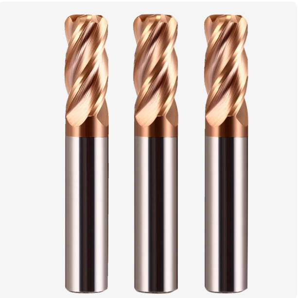
Earlier this year, we received an urgent call from a German aerospace component shop. They were experiencing frequent micro-chipping on their 4-flute end mills while machining 17-4PH stainless steel. A single tool often failed to finish even half a disk cavity. On-site engineers lowered cutting speeds—extending cycle times by nearly 30%—yet the built-up edge (BUE) issue actually got worse.
Scenarios like this happen constantly in our technical support work. When selecting cutting tools for metal, many shop managers fall into a common trap. They focus entirely on machine spindle power or CAM toolpaths while overlooking the tool’s core material science and geometry.
With fifteen years of experience in tool R&D, we have solved hundreds of on-site challenges for global clients. A cnc end mill for metal maintains high feed rates under extreme conditions through a precise interplay of three factors: substrate grain size, edge honing precision, and coating adhesion strength. Whether using a corner radius end mill to distribute stress on superalloys or polishing chip gullets for high-volume runs, real efficiency gains are always hidden in microscopic details.
In this article, we skip abstract theories and share real-world shop-floor data. As a specialized carbide cutting tools manufacturer, we break down the core engineering logic behind high-performance tooling. Our goal is simple: to help you squeeze the maximum service life out of every tool in your shop.
Is there a tool in your facility right now that is needlessly eating into your profits while spinning in the spindle—simply because the parameters are off?
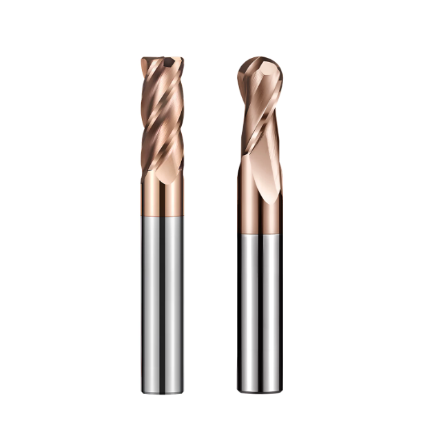
Why Formula and Powder Quality Define a High-Quality Carbide Cutting Tools Manufacturer
On the shop floor, we often hear peers complain that two carbide tools with identical geometries perform worlds apart on hard metals. The real difference lies not in the final grinding, but in the tungsten carbide powder formulation and sintering process. With 16 years of R&D experience, we know that slight deviations during powder preparation or Hot Isostatic Pressing (HIP) are magnified under heavy cutting loads.
We liken the carbide substrate to the “cement and aggregate” of a building; the powder formula is our core trade secret. If the substrate fails under high heat and stress, even the advanced coating won’t prevent tool failure. As a dedicated carbide cutting tools manufacturer, building a flagship product is a long-term effort to achieve the ideal mechanical balance within the material’s microstructure.
How Grain Size and Cobalt Content Balance Hardness and Chipping Resistance for Tools Metal Cutting
When evaluating machining solutions for clients, we constantly balance hardness against toughness. Sub-micron or ultra-fine tungsten carbide grains increase substrate hardness and compressive strength. However, pursuing hardness alone makes the tool brittle during interrupted cuts or vibrations. Cobalt acts as the binder phase, boosting impact toughness while slightly reducing heat resistance.
There is no universal formula when choosing substrate materials for tools metal cutting. For heavy-duty roughing and interrupted cuts, we increase cobalt content and optimize grain size to absorb shock. For finishing hardened mold steels above HRC60, we choose low-cobalt, ultra-fine grain grades. Balancing these properties at the microstructural level prevents premature edge chipping during high-speed machining.
Insights from Client Cases: Why Low-Cost Carbide CNC Milling Cutters Show Micro-Porosity
Last year, a North American client called us after several new tools snapped at the shank while machining aerospace aluminum and stainless steel. Laboratory scanning and fractographic analysis revealed micron-scale porosity and “cobalt pooling” near the fracture points. Under high-speed rotation and cyclic stress, these internal voids act as stress concentrators that trigger rapid fatigue failure.
These defects usually stem from cost-cutting measures, such as shortened sintering cycles or using recycled carbide powders. In low-cost carbide cnc milling cutters, the lack of high-pressure HIP equipment leaves residual gases and impurities inside the metal. Ensuring a dense, pore-free microstructure in every tool is our non-negotiable standard to protect your machine uptime and productivity.
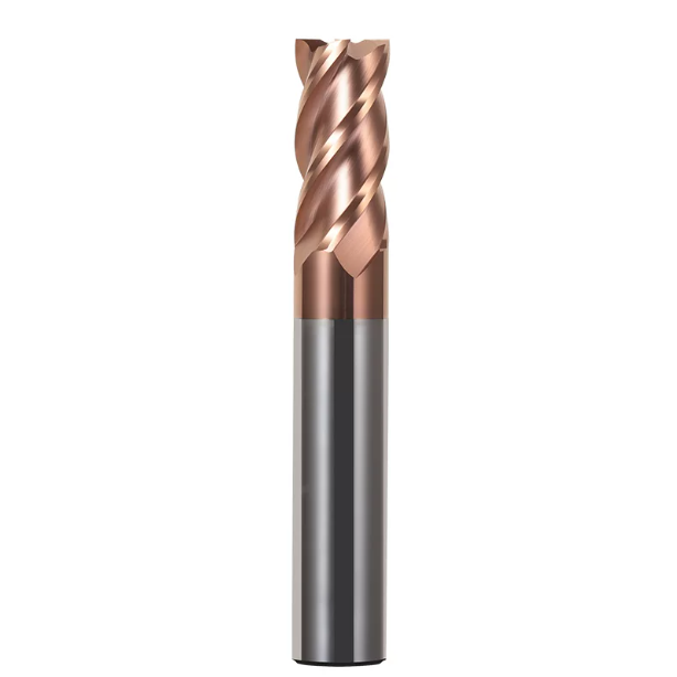
Geometric Design: How to Keep a CNC End Mill for Metal Stable Under Heavy Cutting
In heavy-duty machining, industry peers often suspect machine rigidity or clamping issues first. However, our on-site tuning experience shows nearly 60% of chatter and chip blockages stem from tool geometry. A cutting tool is a dynamic structure that guides chip flow under high-speed rotation. If the rake angle, relief angle, and flutes are not optimized, even a high-torque spindle cannot perform.
Years of grinding experience have taught us that geometric design decouples cutting forces from chip space. When designing a cnc end mill for metal for heavy loads, we must ensure core strength while maintaining open chip flutes. This requires micron-level grinding precision. Even a slight error can cause piercing squeals or instant tool breakage on the shop floor.
Variable Indexing and Variable Helix: Real-World Tuning to Eliminate Chatter
When machining sticky materials like TC4 titanium or 316L stainless steel, engineers are often plagued by resonant squealing. We assisted a European mold maker whose standard tools vibrated violently in deep slots above 3,500 RPM, ruining the finish. We replaced them with our end mills featuring variable indexing and variable helix angles, which immediately suppressed the vibration.
This design disrupts the resonant frequency. Standard tools with equal tooth spacing strike the metal at identical intervals, causing severe resonance with the spindle. Staggering the teeth (such as 88°–92°) and using variable helix angles alters the frequency of each cutting force pulse. This asymmetrical geometry is the most reliable way to eliminate chatter without reducing cutting parameters.
Rake Angle and Flute Polishing: Details Affecting High-Performance Tools Metal Cutting
Beyond chatter, chip packing in the flutes is another major cause of tool breakage. High heat and pressure can weld ductile metal chips to the rake face, forming a built-up edge. Increasing the rake angle by 2 degrees reduces cutting resistance, but it also weakens the edge. Finding the right balance between sharpness and rigidity requires deep manufacturing expertise.
When producing our high-end tools metal cutting series, we apply a micron-level mirror polish to the flutes after grinding. Polishing drastically lowers friction, letting chips slide out smoothly after curling. This prevents dangerous heat buildup caused by chip clogging. If you face poor chip evacuation, check the flute surface finish under a microscope.
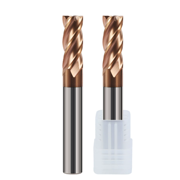
Corner Radius Design: How a Corner Radius End Mill Extends Tool Life by Over 50%
When machining superalloys or hardened steels, the tool tip is usually the first point of failure. Sharp corners on square-end mills have minimal volume for heat dissipation, leading to severe stress concentration and micro-chipping within minutes. Over a decade of field experience shows that replacing sharp corners with a precise radius fundamentally alters force and heat distribution.
Adopting an appropriate corner radius protects the fragile tip and improves the cutting cross-section during feeds. Blending the radius with the side and bottom edges creates a massive jump in impact resistance during deep cuts. For machine shops plagued by fast tip wear, switching to a high-performance corner radius end mill is the fastest path to longer tool life.
Why a Corner Radius End Mill Disperses Heat and Stress Better Than Square End Mills
A square end mill encounters concentrated point-contact forces the moment it engages metal. This localized stress causes temperatures to spike above 800°C, breaking down the substrate and peeling the coating. In contrast, the arc-shaped edge of a corner radius end mill spreads cutting forces evenly over a longer contact area, gradually transitioning cut thickness.
This force dispersion delivers clear practical benefits. In a test on aerospace disk components, a square-end mill showed 0.2 mm of tip wear after just 15 minutes. An end mill with an R0.5 corner radius cut continuously for over 40 minutes with minimal wear. For slotting or heavy roughing, replacing sharp corners with radiused edges is the smartest way to extend tool life.
Micron-Level Honing Control: Customizing the Edge Condition of a Metal Cutting Tool
Assessing if a tool is “sharp enough” by hand or magnifying glass is a common mistake. A freshly ground cutting edge has microscopic, fragile serrations that instantly chip under heavy loads, causing catastrophic edge failure. After initial grinding, we must apply precise edge honing using nylon brushes, abrasive slurry, or air blasting.
Customized honing is not simply rounding the edge; it means controlling the radius based on workpiece material. When tailoring a high-quality metal cutting tool for soft aluminum or copper, we maintain a 5 to 8-micron honing radius for maximum sharpness. For hardened steels (HRC 55+) or interrupted cuts, we increase the edge radius to 15–25 microns with a negative land for maximum shock resistance.
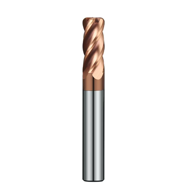
Nano-Coatings and High-Temperature Adhesion: Anti-Peeling Strategies for Carbide CNC Milling Cutters
At high cutting speeds and feeds, tool coatings are no longer rust-proof coats; they are the first line of defense against high temperatures and intense friction. We often see failed tools where the substrate shows no wear, yet the coating has flaked off due to poor adhesion. Once the coating detaches, the vulnerable carbide base rapidly softens and oxidizes at elevated temperatures.
From a manufacturing standpoint, we must subject carbide substrates to rigorous surface cleaning and plasma etching before deposition to ensure atomic-level adhesion. For carbide cnc milling cutters facing heavy friction and thermal shock, selecting the right PVD process and multilayer nano-structure design is crucial for maintaining wear resistance under extreme heat.
AlTiN vs TiSiN: Selecting Coatings for Hardened Steels (HRC 50+) and Superalloys
When machining hardened steels over HRC 50 or superalloys, many focus solely on coating hardness. AlTiN and TiSiN are our top PVD nano-coatings, but they differ in structure and breakdown mechanisms. AlTiN forms a dense aluminum oxide layer at high heat for superior oxidation resistance. In contrast, TiSiN uses a silicon-doped nanocomposite structure to achieve hardness over HV3800 and prevent thermal diffusion.
We tailor coating choices to specific material traits. For sticky, low-thermal-conductivity nickel alloys like Inconel 718, we recommend high-aluminum AlTiN for superior toughness against friction. For high-hardness mold steels like SKD11 (HRC 50–65), we specify TiSiN coatings. Matching coating physics to workpiece properties prevents thermal annealing during high-speed dry machining.
Thermal Shock and Cooling Strategies: Protecting the Coating Life of a CNC End Mill for Metal
In heavy or interrupted milling, coolant application often dictates coating survival. Laboratory tests show early micro-cracking is usually caused by thermal stress from rapid temperature swings rather than abrasive wear. As the cutting edge engages the metal, tip temperatures spike above 800°C; when it exits and meets cold coolant, the temperature plummets, creating severe thermal stress cracks.
When high-speed milling with a hard cnc end mill for metal, our technical advice for clients is clear: choose air blow or MQL over high-volume flood coolant whenever possible. Maintaining a stable, high cutting temperature keeps the coating in an optimal oxidation-resistant state. High-pressure liquid cooling is only necessary for aluminum or titanium to evacuate chips and prevent built-up edge (BUE).
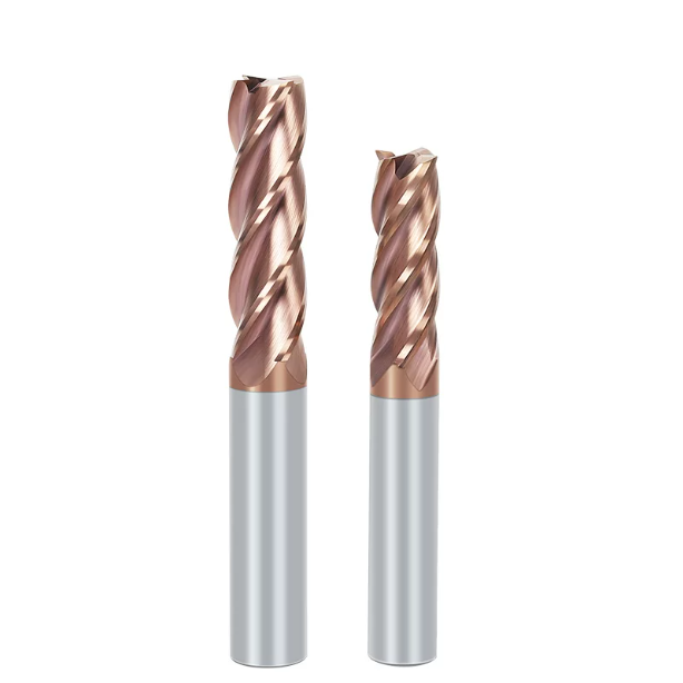
On-Site Machine Setup: Turning High-Quality Tools Metal Cutting into Workshop Savings
Exceptional substrates, geometries, and nano-coatings mean little if poor on-site setups turn them into expensive assets gathering dust. When supporting international clients, our goal is never pushing expensive tools, but helping shops reduce cost-per-part and tool-change frequency without overloading machines. Efficient machining requires aligning tool limits with machine rigidity, workholding, and CAM toolpaths.
Transforming high-end tools metal cutting into financial gains demands a holistic optimization view. From selecting sub-micron substrates and variable-pitch geometries to choosing proper cooling method strategies, on-site setup represents the final mile of converting manufacturing physics into stable cutting output. Matching parameters to shop conditions makes cost reduction a natural outcome.
Matching Parameters (Vc, Fz, Ap, Ae): Optimizing Cycle Times in Machine Shops
When optimizing cutting speed (Vc), feed per tooth (Fz), axial depth (Ap), and radial depth (Ae), the common mistake is copying catalog values blindly. Catalogs assume ideal rigidity, whereas real shop conditions—such as fixture stiffness and tool overhang—vary widely. Applying large radial depths on long-overhang setups triggers severe chatter and premature edge chipping.
We prefer a high-efficiency trochoidal milling strategy with small radial and large axial depths. When machining titanium or stainless steel, limit radial depth (Ae) to 5%–10% of tool diameter while pushing axial depth (Ap) to 1.5–2 times the flute length. Combining this with higher spindle speeds concentrates heat in the chips, reducing spindle load and cutting cycle times by over 30%.
Spindle Load to Chip Shape: Diagnosing Abnormal Wear on a Metal Cutting Tool
Experienced engineers rely on sight and sound to judge cutting performance. You do not need to stop the machine and inspect the tool under a microscope; simply watching the spindle load meter and ejected chip shapes yields an accurate diagnosis. A rising spindle load without path changes, or a sound shifting from a crisp tone to a dull thud, indicates edge wear and spiking cutting forces.
Chips offer direct insight into process health. When cutting steel, uniform “C” shapes or tight spirals with a faint purple or blue oxide layer indicate heat is leaving the workpiece properly. Irregular, stringy chips or charred black colors signal flute packing or thermal coating failure. Adjusting feeds or depths early saves both workpiece and metal cutting tool before catastrophic failure occurs.
High-efficiency metal cutting is a systematic undertaking—from raw tungsten carbide formulations to heavy-duty geometries and precise coating-parameter matching. If your shop faces tool life issues, chatter on superalloys, or parameter uncertainties, feel free to share your application details, drawings, or material specs with us. Together, we can analyze your on-site data to identify the most effective machining solution.






