
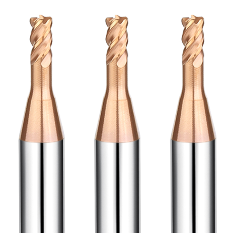
A few months ago, a client from Ohio brought us several 4-flute tools with completely shattered cutting edges. They were machining 4140 pre-hardened steel (HRC 38–42) and experiencing wildly inconsistent tool life. Some tools ran smoothly through 30 parts, while others produced a piercing screech by the fifth part before snapping instantly. The shop supervisor immediately blamed “bad carbide rod quality” or “poor coating adhesion.”
However, when we examined the broken tools under a microscope and reviewed their toolpaths, the real issue emerged. It was not a material defect at all. The shop had simply applied generic cutting parameters while completely ignoring how core thickness and corner radius impact chip evacuation.
Over 15 years of tool design and CNC shop troubleshooting, we have seen this exact scenario repeat across hundreds of machine shops. When selecting carbide end mills for metal, engineers often focus 90% of their energy on carbide grades or coatings like AlTiN and nACo. Yet, they overlook the most fundamental physical principle: tool geometry.
Coating and substrate only set the upper limit of wear resistance, but geometry controls cutting force distribution, heat dissipation, and chatter resistance. This is vital when machining tough alloys, executing high-speed milling with an HRC55 end mill, or running heavy-stock removal using roughing end mills. A rake angle off by just two degrees can cause catastrophic heat accumulation. Selecting the right metal cutting tools requires balancing tool physics with machine rigidity.
Want to know how we helped that Ohio client boost tool life by 2.5 times without changing the tool substrate or coating? We simply optimized seven key geometric factors.
Why Price Isn’t the Only Factor in Metal Cutting? Lessons on Carbide End Mill Geometry from Real-World Tool Failure Cases in Western Workshops
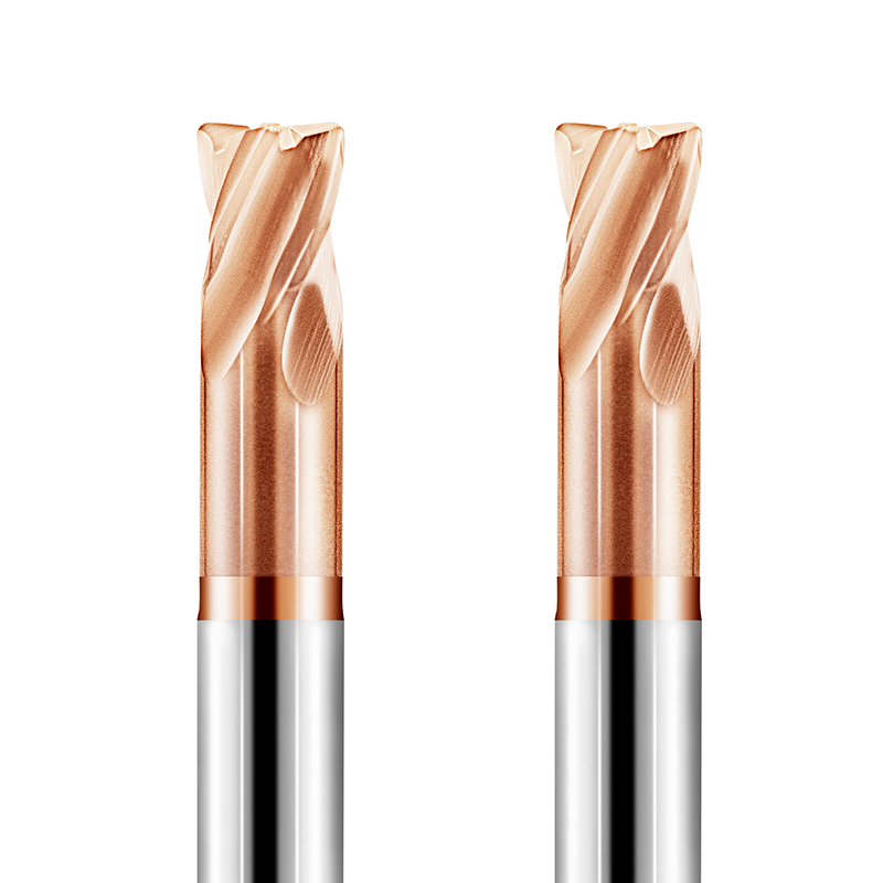
Last month, a purchasing manager at a Tier 1 German automotive supplier complained that our high-performance milling cutters cost 30% more than their current supplier’s. However, just three days after putting the cheaper tools into mass production, spindle alarms and frequent tool breakage brought their automated line to a halt. When we analyzed the failed carbide end mills for metal, we found that the generic flute design failed to evacuate viscous stainless steel chips, causing chip recutting and sudden force spikes that destroyed the tools.
In CNC machine shops, managers often view cutting tools merely as consumables, attempting to cut costs by driving down unit prices. Yet, based on our 15-plus years in tool manufacturing and process optimization, this approach often backfires. Low-cost tools feature standardized geometries that overlook material-specific heat and chip-breaking dynamics. The costs of downtime, scrap, and spindle damage caused by poor geometry far outweigh the initial savings on metal cutting tools.
16 Years of Process Optimization Experience: The Root Cause of Most Metal Cutting Tool Failures Is Incorrect Geometry Selection
In hundreds of technical support cases we handled for Western clients, over 80% of abnormal tool failures were initially blamed on “impure raw material” or “coating delamination.” However, microscopic analysis of these failed metal cutting tools almost always revealed a mismatch between tool geometry and actual operating conditions. Engineers often focus on substrate grain size or PVD coating hardness, forgetting that geometry is the physical structure bearing loads and guiding chip flow.
When machining hard materials, an overly sharp edge with a large rake angle will suffer micro-chipping under high normal forces. Conversely, when cutting sticky titanium alloys with carbide end mills for metal, an excessive edge-honing radius causes the tool to extrude rather than cut, generating extreme heat. From polished flute roughness to core-to-diameter ratios, minute geometric errors multiply under high feed rates, causing premature breakage or terrible surface finishes.
A Common Pitfall for Western Customers: Using General-Purpose Geometries Instead of Application-Specific Carbide End Mills for Metal
In daily technical support with European and American clients, we notice even seasoned engineers falling into the “universal tool” trap. Many shops buy general-purpose carbide end mills for metal to simplify inventory for light-duty, high-mix machining. However, the weaknesses of compromise geometries become glaringly apparent during mass production, deep-cavity roughing, or high-feed cuts in tough alloys.
To balance strength and evacuation, general-purpose tools compromise on helix angles, core thickness, and relief angles. They lack both the large chip pockets needed for soft metals and the thick core rigidity required for hard steels. When pushed in High-Efficiency Milling (HEM), these general-purpose metal cutting tools vibrate violently and break, proving that real factory cost savings come from application-specific geometry.
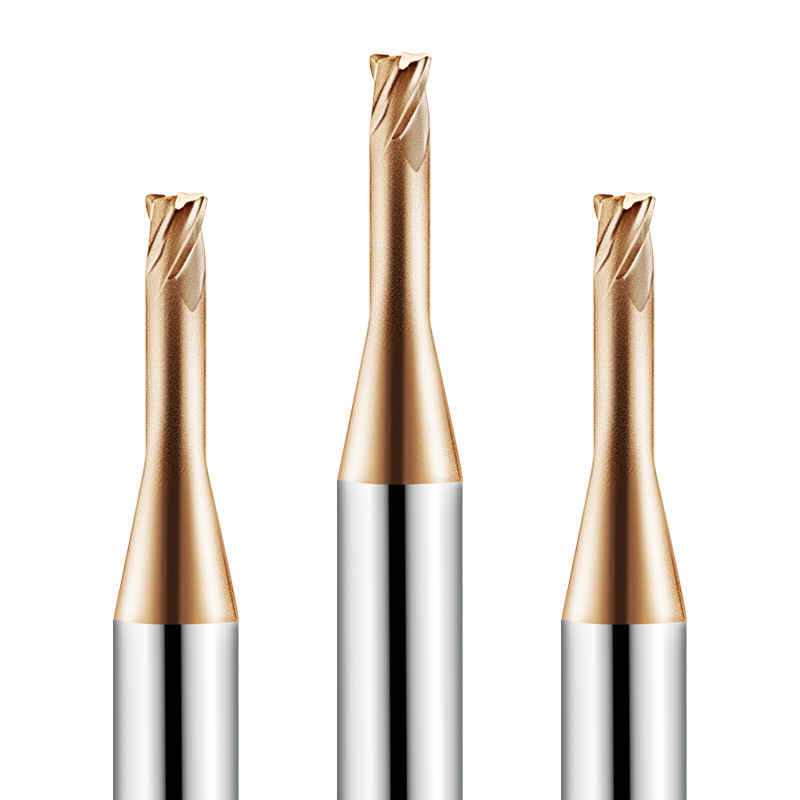
Factor 1: Helix Angle—Balancing Vibration and Chip Evacuation for Stainless Steel and Hardened Steel
The helix angle directly controls how smoothly the cutting edge engages and exits the workpiece. When tackling stainless steel work-hardening or high forces in hardened steel, shops often reduce axial depth of cut (AP), ignoring how helix angles split axial and radial forces. A low helix angle offers high axial rigidity and ample chip clearance for end mills for metal but creates heavy entry impacts; a high helix angle cuts smoother but directs force into the spindle and narrows the flute.
When setting up jobs, we remind engineers that choosing a helix angle is a dynamic trade-off between suppressing chatter and evacuating chips. Different metals demand drastically different chip formation paths. Using an ill-matched helix angle on carbide end mills for metal not only creates a screeching noise but also accelerates flank wear, making force-distribution analysis essential for stable machining.
Choosing Between 35°, 38°, and 45°: Mechanical Force Distribution for Different End Mills
When customizing end mills for metal, the 35° to 45° range is our primary focus. For tough 304 or 316 stainless steels, a 45° helix is our first choice because its sharp shearing action “rolls” work-hardening chips out, lowering heat. However, the narrowed flute requires high-pressure coolant to prevent packing. For steels over HRC 50, we switch to a 35° helix, providing maximum flute clearance and a stronger tool tip to absorb heavy cutting shocks.
The intermediate 38° helix serves as a versatile compromise for general alloy steel milling. During setup, we never blindly pick an angle; we evaluate spindle interface rigidity (BT40 vs. HSK), tool overhang, and coolant pressure. Matching the correct helix angle ensures your metal cutting tools receive either the sharp shearing action or the rigid structural backing required at impact.
How Variable Helix Geometry Helped a German Client Eliminate Chatter Marks in Deep-Cavity Milling
A Stuttgart mold maker reached out when machining deep-cavity 42CrMo4 steel using standard constant-helix tools at 4xD overhang. Cuts deeper than 0.5xD caused severe resonance and chatter marks, while lowering speeds only increased tool rubbing and micro-chipping. Instead of recommending expensive stock, we re-engineered their carbide end mills for metal with a variable helix (35°/38°) and unequal flute spacing.
Unequal geometry disrupts the constant harmonic frequency of tooth engagement, breaking the physical conditions that trigger chatter. Maintaining their original speed and feed rates, the client eliminated chatter marks entirely, achieved a surface finish better than Ra 0.8, and boosted tool life by over 40% using these optimized end mills for metal.
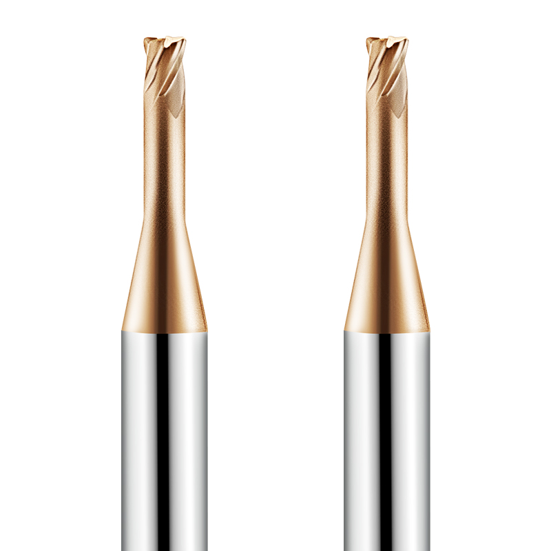
Factor 2: Core Thickness (Core-to-Flute Depth Ratio)—Balancing Rigidity and Chip Evacuation Space for Roughing End Mills
During heavy-duty cutting and high-efficiency milling, a tool’s core thickness is often the hidden factor determining success or failure. Core thickness is the diameter of the solid metal at the cutter’s center—measured as a percentage of the outer diameter. Based on our 15-plus years of manufacturing and shop-floor optimization, core thickness dictates bending rigidity and torsional vibration resistance. However, expanding the core inevitably shrinks the flute depth, restricting chip space and leading to severe clogging.
For roughing end mills built for high stock removal, balancing core rigidity and flute capacity is the ultimate design challenge. A core that is too thin undergoes microscopic deflection under heavy radial loads, triggering severe chatter and breakage. Conversely, an oversized core compresses chips during deep slotting; the resulting heat and pressure will instantly shatter cutting edges. This geometric ratio must be dynamically adjusted based on cutting depths and material chip-breaking traits.
Why Does Poor Chip Evacuation During Roughing Lead to Immediate Edge Chipping?
In heavy roughing, most severe edge chipping incidents stem from instantaneous overloading caused by chip recutting rather than poor tensile strength. When roughing end mills cut steel at high feed rates, their serrated edges generate vast amounts of short chips. If flute depth and curvature are poorly designed, these hot, hard chips cannot evacuate quickly. Instead, the rotating cutter re-entrains them directly into the cut zone.
This secondary chip compression causes cutting forces to spike several-fold in mere milliseconds—far exceeding the carbide substrate’s physical limits. Microscopic analysis in customer workshops repeatedly shows that edge chipping is accompanied by chip fusion and heat scars. Poor chip evacuation acts like a hydraulic press, directly crushing the cutting edge. Ensuring clear chip channels is just as critical as providing tool body rigidity.
Large Core Thickness vs. Deep Flutes: Balancing Rigidity and Chip Management in Roughing End Mill Manufacturing
As tool manufacturers, we constantly seek the ideal balance between high core rigidity and deep flute chip capacity. For slotting or deep cavity work, we maintain a 55% to 60% core with polished flutes to prioritize smooth chip curling and evacuation. For trochoidal milling or low-radial-engagement paths—where chip pressure drops—we increase core thickness on roughing end mills to 65% or higher for maximum vibration resistance.
Beyond fixed percentages, we utilize a tapered core design: thinner at the tip for chip clearance, and thicker toward the shank for maximum support. This asymmetrical structure excels at absorbing high torsional stresses during heavy-duty cutting. No single core ratio fits every scenario; selecting geometry matched to your toolpath, machine rigidity, and material chip formation is the key to preventing roughing failures.
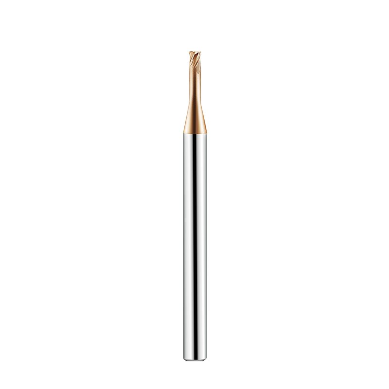
Factor 3: Corner Radius—The Physics Behind Extended Tool Life in Corner Radius End Mills
The sharp corner of a standard square-end mill represents a severe structural weak point. When engaging metal at high feed rates, total cutting forces and localized heat concentrate directly on that microscopic vertex. In our analysis of over a decade of tool failures, most square cutters did not fail from flank wear. Instead, microscopic chipping initiated at the sharp corner and propagated rapidly down the primary cutting edge.
By incorporating a small tip radius, corner radius end mills physically alter force transmission and heat distribution. The radius increases the carbide volume at the tip—enhancing impact resistance—and distributes concentrated loads evenly along the arc. For workshops prioritizing machining stability and batch consistency, strategic use of corner radii is essential for eliminating premature tool failure and extending cutter service life.
Force Comparison: Square vs. Corner Radius End Mills—Data on Eliminating Stress Concentration
From fracture mechanics and finite element analysis, stress concentration at a square tool’s sharp corner is several times higher than on a tool with a corner radius. Shop-floor measurements show that when a square tip contacts the workpiece, the microscopic apex endures normal compressive forces reaching several gigapascals. Conversely, using corner radius end mills of the same diameter (e.g., R0.5 or R1.0) reduces peak tip stress by 30% to over 50%.
This improved stress distribution dramatically boosts resistance to micro-chipping. Square tips lack substrate support and flake easily during deep or interrupted cuts. Curved edges on corner radius end mills gently channel impact forces into the tool body. For cavity or face milling without strict right-angle requirements, opting for a corner radius geometry is a smart trade-off for superior stability.
Real-World Optimization Case: Doubling Tool Life by Switching to Corner Radius End Mills for Titanium Alloys
A California aerospace manufacturer approached us regarding severe tool wear when batch-machining Ti-6Al-4V titanium structural parts. They were using square-cornered tools at low cutting speeds, yet tool tips chipped in under 40 minutes, causing loud chatter and surface scoring. The shop supervisor reduced feed per tooth to survive, but this extended cycle times and exacerbated severe work hardening.
Reviewing their drawings revealed that cavity bottoms did not require sharp right-angle corners. We recommended replacing square tools with corner radius end mills featuring an R0.8 tip radius while increasing feed per tooth by 15%. The radius added critical substrate volume to dissipate titanium’s intense heat and eliminated sharp-corner chipping. Without changing machines or coolant, actual cutting time per tool jumped from 40 to over 90 minutes, halving total tooling costs.
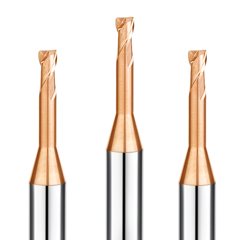
Factor 4: Flute Count—Depth of Cut and Chip Control for HRC55 End Mills and Soft Metals
Flute count dictates engagement frequency during rotation and determines physical chip space inside the tool body. A common shop-floor mistake is assuming more flutes allow for infinitely higher feed rates. In reality, adding flutes shrinks each individual chip gullet. When cutting soft metals like aluminum or mild steel—which yield large, gummy chips—too many flutes trigger rapid clogging, extreme heat, and cutter breakage. Conversely, cutting hard steels with too few flutes starves core thickness, causing deflection.
Selecting the right flute count means striking a balance between chip load per tooth, evacuation space, and overall rigidity. When milling mold or pre-hardened steels, choosing the correct configuration for an hrc55 end mill directly impacts spindle load stability and surface finish. A well-matched flute count prevents cutting force spikes and forms the foundation for high-efficiency metal removal and chip control.
Matching Feed Rates and Flute Counts for HRC55 End Mills When Machining Mold Steel
When machining HRC55 mold steels (e.g., NAK80, SKD61, or hardened P20), engineers often ask whether to choose a 3-flute, 4-flute, or 6-flute tool. For heavy roughing or slotting with large stock removal, a 3-flute or 4-flute hrc55 end mill is safer because larger chip pockets prevent hard chips from jamming. For feed rates, a 4-flute tool offers higher step-cutting efficiency than 2- or 3-flute options while maintaining a healthy feed per tooth (IPT).
However, applying 2- or 3-flute soft-metal tools to HRC55 mold steel is disastrous; their thin core deflects violently under heavy loads, causing immediate edge chipping. We advise selecting flute count based on toolpath: choose 4 flutes for roughing to balance strength and chip evacuation, but switch to multi-flute geometries for sidewall finishing or low-radial-engagement dynamic milling.
Why We Strongly Recommend Multi-Flute, Low-Radial-Engagement Geometries for Finishing Hardened Steel (HRC55)
When transitioning to finishing or semi-finishing HRC55 hardened steel, strategies shift from stock removal to high precision and surface finish. At this stage, we strongly recommend a 6-flute or 8-flute hrc55 end mill paired with small radial depths of cut (Ae of 2% to 5% D) and high table feeds. The multi-flute design maximizes the core thickness ratio, providing exceptional flexural rigidity that suppresses tool deflection in hard materials.
Multi-flute geometries also smooth out cutting force fluctuations during high-speed rotation. Because time intervals between tooth engagements are extremely short, resulting chips are micro-thin, keeping heat concentrated in the chip rather than the cutter or workpiece. When helping clients eliminate chatter in hardened molds, replacing 4-flute tools with specialized 6-flute geometries improved surface finish by a full grade and produced remarkably uniform flank wear.
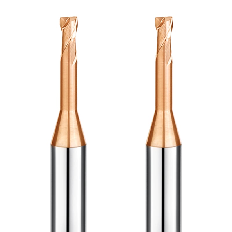
Factor 5: Rake & Relief Angles—The Balancing Act Between Cutting Sharpness and Edge Strength
The rake angle and relief angle represent a perpetual mechanical trade-off in micro-geometric tool design. The rake angle determines sharpness and shearing resistance upon engagement, while the relief angle controls frictional contact between the flank face and the machined surface. Over 15 years of tool grinding and setup, we have seen engineers focus solely on whether a tool cuts fast, ignoring how sharp edges weaken structural support. An excessive rake angle leaves cutting edges fragile under load; conversely, negative angles shift cutting into violent extrusion.
Finding the sweet spot for these angles balances minimizing cutting resistance against maintaining physical edge integrity. This is particularly critical when cutting metals with varying ductility and hardness. Subtle angular adjustments determine whether the cutter smoothly slices or forcefully tears through material. Understanding how angle changes alter micro-level forces enables precise geometric adjustments to resolve issues like built-up edge or edge chipping when selecting carbide end mills.
Rake Angle: Why a Positive Rake Angle is a Lifesaver for Carbide End Mills When Machining Highly Ductile Metals
When machining ductile materials prone to work-hardening—like stainless steel, copper, or titanium—failing to dissipate forces quickly causes chip welding and built-up edge. In these scenarios, carbide end mills with large positive rake angles offer an irreplaceable advantage. Positive rake angles increase the chip flow angle, allowing chips to slide smoothly along flutes with minimal resistance, significantly lowering cutting zone temperatures and spindle loads.
However, positive rake angles are a double-edged sword that thins the supporting wedge of material beneath the cutting edge. Using aggressive positive rake angles on steels over HRC 50 causes edges to flake off upon initial impact. Our grinding rule is simple: use large positive rake angles on soft, ductile metals to reduce shear forces, but reduce or invert rake angles on hard, brittle metals to maximize impact resistance.
Double Relief Geometry: The Secret to Preventing Flank Rubbing in Metal Cutting Tools
Relief angle magnitude directly affects physical interference between the tool’s flank face and the workpiece. Small relief angles force the flank face to rub against machined surfaces like a brake pad, destroying surface finish and accelerating wear. Conversely, excessive relief angles remove supporting substrate, leaving edges prone to micro-chipping under lateral loads. To solve this dilemma, high-performance metal cutting tools rely on double relief (primary and secondary) geometry.
Double relief structures use a primary relief angle to maintain a narrow, precise land width for robust edge support. A larger secondary relief angle immediately follows, expanding clearance to eliminate unnecessary frictional contact. In practical side milling and deep-cavity work, double relief geometry minimizes frictional heat expansion, allowing metal cutting tools to maintain dimensional stability and slow normal flank wear rates.
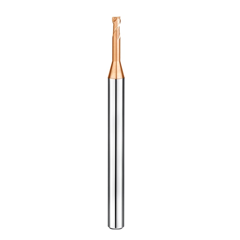
Factor 6: Land Width & Edge Prep (Land Width and Honing/Micro-geometry)—The Hidden Details Determining Initial Micro-chipping
To the naked eye, a ground end mill’s cutting edge appears as a perfectly sharp, flawless line. However, optical microscopy reveals that as-ground edges without edge preparation are riddled with microscopic serrations and grinding cracks. When engaging metal at thousands of RPM, these defects turn into stress concentration points that cause flaking within minutes. This explains why new, un-honed tools often exhibit inconsistent tool life or fail abruptly during initial entry.
Controlling land width and honing parameters establishes a microscopic line of defense along the cutting edge. For high-performance carbide end mills, micro-geometric prep actively manages the tool’s initial wear phase. Optimized honing radii and chamfers smooth out force distribution along the edge, transforming fragile corners into compression-resistant structures that lock in machining stability across the entire cutter lifespan.
Honing Isn’t Always Better When “Rounder”: How Micro-geometry Affects Initial Wear in Carbide End Mills
Shop supervisors often pursue aggressive edge honing under the assumption that rounder edges equal greater wear resistance. However, if the honing radius (K-factor) is ground too large, the edge fails to penetrate metal cleanly, degrading the process into severe plowing. This intense friction generates excessive heat—causing sticky metals to adhere to the edge—and work-hardens the workpiece, shortening the service life of carbide end mills.
Conversely, un-honed edges on stainless steel or titanium suffer rapid micro-chipping under heavy cutting stresses. During manufacturing, we adjust honing dimensions based on material hardness and ductility. For tough, gummy alloys, we apply a subtle 5–10 micron hone to eliminate serration defects while preserving sharp cutting action; for hard steels, we enlarge the radius to create smooth transitions that withstand impact.
Negative Chamfer (T-Land) Geometry: Protecting the Cutting Edge from Chipping During High-Speed Machining with HRC55 End Mills
When cutting materials over HRC 50, edge honing alone cannot withstand the immense normal forces exerted on the cutting edge. Under high-stress conditions, grinding a minute negative chamfer (T-Land, 0.05–0.15 mm wide at -10° to -20°) onto the rake face of an hrc55 end mill is vital for preventing catastrophic chipping. Negative chamfers transform tensile stress at the cutting tip into compressive stress, which carbide withstands far better.
In high-speed dry milling or hard mold finishing, negative chamfers act as robust edge protectors that absorb mechanical shock and thermal cycling. Although negative chamfers slightly increase cutting resistance, pairing them with High-Speed Machining strategies—high RPMs and narrow radial cuts—yields a massive boost in edge toughness. Mastering chamfer width and angle combinations helps overcome chipping challenges on an hrc55 end mill.
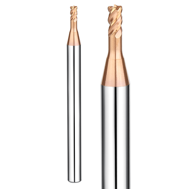
Factor 7: Cutting Edge Roughness—The Impact of Grinding Quality on Cutting Forces
Tool performance depends heavily on manufacturing quality, not just blueprint geometry. Microscopic roughness along the cutting edge and chip flutes acts as an invisible factor limiting cutter performance. When tools engage metal at high spindle speeds, microscopic grinding wheel marks or surface irregularities create physical obstacles to chip flow, significantly increasing cutting resistance and heat generation.
When selecting high-performance metal cutting tools, edge grinding precision directly dictates the initial friction coefficient. Rough grinding leaves microscopic peaks that trigger intense stress concentrations and premature micro-chipping upon contact; simultaneously, rough flute surfaces impede smooth chip curling. Optimizing 5-axis grinding processes and edge polishing reduces cutting resistance at the source, ensuring smooth operation in heavy-load or ductile metals.
Grinding Wheel Grit and Five-Axis Grinding Processes: How High-Quality Grains Reduce Cutting Resistance in Carbide End Mills
When grinding carbide end mills on 5-axis CNC machines, wheel grit size and dressing quality dictate edge microscopic quality. Low-cost tools are often manufactured using coarse diamond wheels for rapid flute grinding, leaving deep scratch marks across rake and flank faces. When these scratches reach the cutting edge, the blade appears jagged under magnification, causing uneven force distribution and localized overloading.
We consistently employ ultra-fine diamond grinding wheels for precision finishing, keeping edge runout and roughness to strict standards. High-quality abrasive grains and precise grinding paths create an extraordinarily smooth, continuous cutting edge. This smooth edge ensures uniform force distribution and drastically reduces friction as chips slide along the rake face, allowing carbide end mills to maintain lower operating temperatures and reduced spindle loads.
Polished Flutes: A Real-World Solution for Built-Up Edge (BUE) in Ductile Metal Machining
When machining ductile alloys like 316L stainless steel, copper, or aerospace aluminum, built-up edge formation is a constant threat. As chips flow rapidly across the rake face, surface irregularities and microscopic scratches impede chip velocity. High heat and pressure cause metal chips to cold-weld to the flute surface, quickly clogging chip evacuation paths and snapping metal cutting tools. A Swiss medical client faced this exact issue when titanium bone screw chips packed inside flutes.
We solved their problem by providing custom carbide end mills with mirror-polished flutes. Polishing reduced flute base roughness to a mirror finish, completely erasing microscopic grinding grooves. The slick flute surfaces allowed chips to curl and eject effortlessly without sticking or cold-welding. Ultimately, the client eliminated tool breakage from built-up edges and achieved flawless mirror surface finishes on internal workpiece walls.
How to Collaborate with Experienced End Mill Suppliers to Customize Geometries Tailored to Your Workshop
With over 15 years in tool grinding and process tuning, we have learned that true high-efficiency cutting requires deep alignment between tool geometry and actual workshop conditions. From helix angles and core thickness trade-offs to corner radii, flute counts, rake angles, micro-honing, and mirror-polished flutes—these seven geometric elements govern cutting performance. Issues like tool failure or chatter often arise because standard catalog geometries reach their physical limits under your specific setup.
As experienced end mill suppliers, our value lies in translating cutting mechanics expertise into custom solutions for your specific operations. If your shop faces machining bottlenecks, re-evaluating overlooked geometric parameters is often the most effective fix. Feeding back real-world performance data to manufacturers who understand micro-geometry physics is the most direct route to breaking efficiency bottlenecks and lowering per-unit production costs.
Why Standard Catalog Tools Can’t Meet Every Requirement—and What Excellent End Mill Suppliers Can Do for You
Standard catalog tools are “greatest common denominator” designs built for routine light-duty machining in common steels or aluminum. However, their compromise structures reveal weaknesses during high-feed dynamic milling, deep-cavity roughing, or cutting tough titanium and superalloys. Standard tools cannot account for your spindle rigidity, holder overhang, coolant pressure, or specialized CAM toolpaths.
Top-tier end mill suppliers act as an extension of your process engineering team rather than mere order-fulfillers. When optimizing your operations, we fine-tune rake angles, customize edge honing, or redesign variable-pitch geometries to eliminate chatter. Tailoring these geometric adjustments to your specific materials and toolpaths yields massive leaps in stability and efficiency without requiring more expensive raw materials.
Submitting Machining Parameters and Samples: How We Assist European and American Clients in Optimizing Specialized Tool Geometries
Through long-term collaboration with Western clients, we developed a streamlined process for optimizing custom tool geometries. If you face short tool life in tough alloys, tight surface finish tolerances, or need to increase Material Removal Rates, compile your shop’s actual cutting data. Gather material grades, spindle interfaces, tool overhang, SFM, IPT, and photos of failed tool wear patterns.
As dedicated end mill suppliers, we welcome technical discussions with fellow engineers and industry peers. You can share your machining conditions, drawing specs, or failed tool samples with us. We will analyze the micro-geometry, force distribution, and failure modes to craft a custom end mill geometry aligned with your shop’s rigidity and workflow.






