
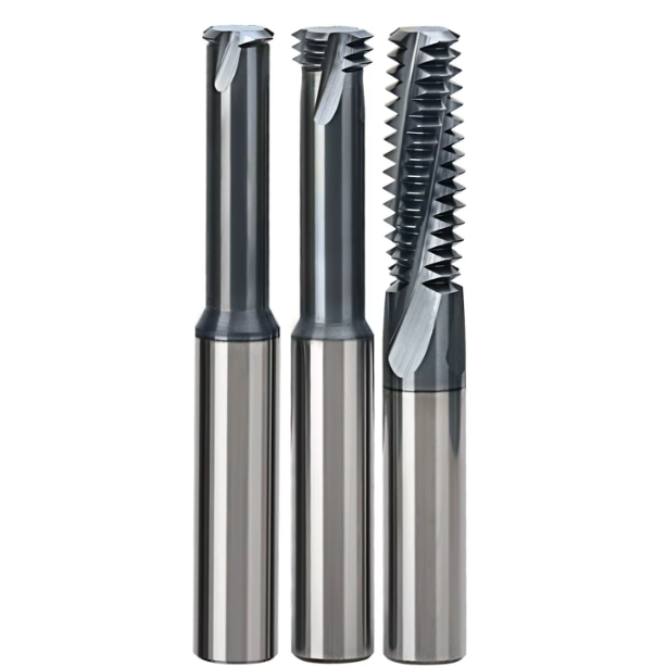
Earlier this year, a long-standing client in Stuttgart, Germany, sent us an urgent message late at night: a batch of large 42CrMo4 wind power valve bodies had been compromised. While machining the final M24 deep hole, a tap seized and snapped without warning, halting production and threatening the castings.
We have witnessed this kind of disastrous last-second failure far too often over the past decade. When workshops face such risks, many supervisors switch to cnc thread milling. However, standard milling cutters often lead to tool deflection, reverse taper, or premature chipping in tough steel alloys.
The issue lies in using general-purpose tools for demanding steel applications. True durability requires specialized thread milling cutters for steels designed with optimized core structures, flute geometries, and edge preparation.
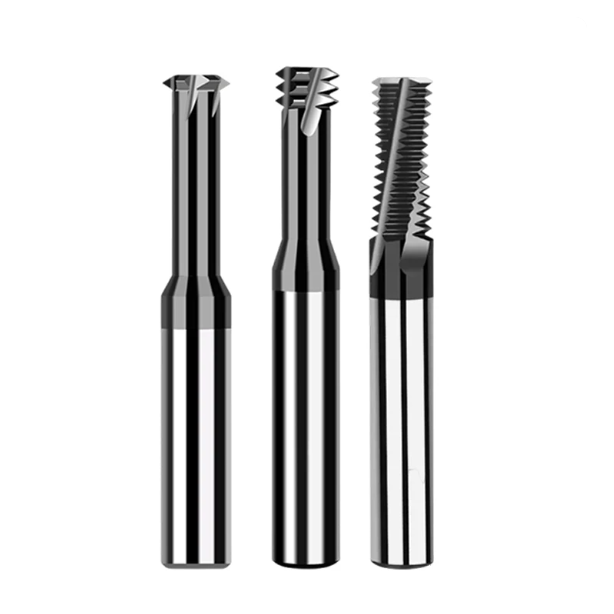
Why Our Workshop Replaced Large Taps with Dedicated Steel-Cutting Thread Mills
If you have ever extracted a broken tap from a nearly finished large casting, you understand why we switched to thread milling over a decade ago. Large taps make full-contact engagement with the steel sidewall, causing radial torque to skyrocket and frequently seizing in blind holes. In contrast, thread milling cutters maintain intermittent point contact, dropping instantaneous cutting forces and minimizing tool breakage.
While taps offer cycle time advantages for small through-holes, process reliability matters more for large steel components. Thread milling provides a vital safety margin: even if a tool wears out, its diameter is smaller than the pilot hole, so it will never jam inside the workpiece. Risking an expensive component just to save a few seconds is a poor trade-off.
The High Cost of Downtime and Tool Breakage Disasters for Western Clients
A North American heavy industry client once faced a six-hour EDM delay to extract a broken carbide tap from a quenched 4140 valve block, which idled an entire flexible line. After switching to stable CNC thread milling, operators only needed to adjust wear offsets when hitting hard spots, completely eliminating those high, hidden downtime losses.
Many workshops focus solely on unit pricing while ignoring comprehensive downtime costs. Pre-hardened mold steels like P20 and H13 make rigid tapping a high-risk operation. Switching to milling makes breakage manageable, securing reliable production scheduling without damaging spindle precision or risking delivery delays.
The Geometric Divide Between Mediocre and Top-Tier Solid Carbide Thread Milling Cutters
Grinding a thread profile is simple, but ensuring a tool resists radial deflection during aggressive steel cutting is difficult. Standard commercial cutters often feature a weak core thickness and lack smooth stress-relief radii. True industrial-grade solid carbide thread milling cutters reinforce the core and optimize flute geometries to withstand heavy bending stresses.
Another indicator of quality is micro-edge honing. Mediocre cutters feature raw, sharp edges that chip instantly in alloy steel, while high-end tools use micron-level air-blasting to create a uniform honing radius. This minor geometric difference determines whether you produce clean threads or chatter-marred, out-of-tolerance holes.
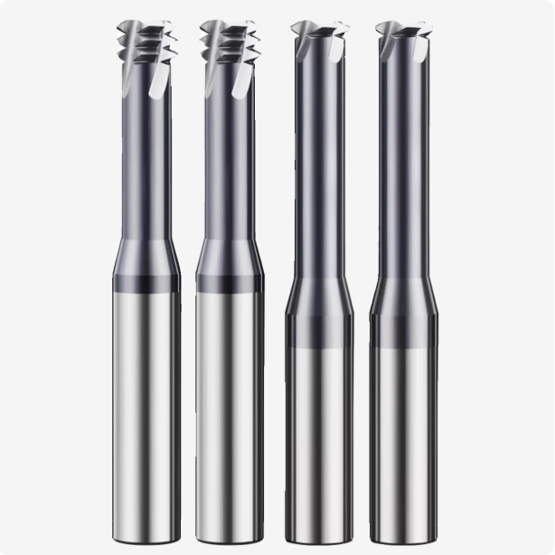
Feature 1: Vibration Resistance via Variable Helix and Pitch in CNC Thread Milling
If you hear a high-frequency squeal during steel machining, uniformly spaced edges are likely triggering harmonic resonance. Traditional tools strike the sidewall at constant intervals, amplifying vibrations at the tool overhang. CNC thread milling cutters featuring variable helix angles and variable pitch disrupt entry phases, shattering periodic force pulses at the source.
This design places high demands on tool grinder interpolation, requiring a trade-off in chip clearance space. We sacrifice a small amount of chip capacity to ensure superior dynamic damping during heavy side milling. For uneven forgings or deep cavities, this vibration-suppression capability maintains accurate thread profiles.
Eliminating Forced Vibration and Pitch Diameter Taper in Deep-Hole Machining
In deep-hole machining exceeding 2.5D, reverse taper occurs when tool deflection causes the Go gauge to pass while the No-Go gauge jams at the bottom. Standard constant-helix tools compound radial forces, causing the tool tip to deviate. Introducing a variable helix angle decomposes cutting resistance, drastically reducing forced vibration and ensuring consistent pitch diameters.
While radius compensation can correct minor taper, it cannot resolve flank chatter. Limiting radial deflection eliminates thread angle distortion at the bottom of deep holes. This allows a single cycle to achieve gauge-fit accuracy of 6H or better without air-cutting passes.
Maintaining Constant Cutting Forces—Tool Tip Wear Comparison in Machining Quenched Steels
High-strength quenched and tempered steel causes tool wear primarily through vibration-induced stress fatigue. Symmetrical-tooth cutters suffer micro-chipping under peak impact forces, accelerating flank friction. Conversely, unequal-pitch designs absorb intermittent loads, maintaining a stable wear band along the cutting edge.
Smoothing cutting force fluctuations prevents alternating stresses from triggering micro-cracks at the grain boundaries. Solid carbide thread milling cutters operating under constant force experience uniform mechanical abrasive wear. This ensures a predictable tool-life degradation curve during mass production.
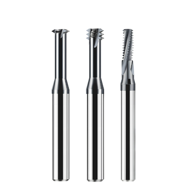
Feature 2: Micro-Rake Angle and Edge Honing Design for Alloy Steels
Many machinists judge tool quality by testing sharpness, yet extreme sharpness causes disastrous edge failure in medium-to-high carbon alloy steels. A sub-micron sharp edge cannot withstand the intense shear stress when engaging high-yield-strength steel. When designing thread milling cutters for steels, we modify the micro-geometry by adding a positive micro-chamfer or neutral support angle.
This balance introduces minor cutting resistance but entirely eliminates localized plastic deformation. Although rigid workholding is required to handle higher radial forces, this approach guarantees geometric stability. Sacrificing minor cutting ease ensures long-term reliability in demanding structural steel applications.
Say Goodbye to Chipping: Why Thread Milling Cutters for Steel Need 10–15μm Edge Honing
Raw ground edges contain microscopic cracks that trigger catastrophic chipping under intermittent impact loads. When an untreated thread milling cutter engages steel, these micro-cracks propagate rapidly along grain boundaries. Applying a uniform 10–15 μm passivation radius smooths out localized contact stresses and suppresses premature fatigue spalling.
Controlling passivation is a strict engineering requirement; deviations exceeding 5 μm alter the cutting mechanism entirely. A radius under 8 μm invites edge damage, while radii over 20 μm cause severe extrusion instead of clean shearing. Maintaining this precise range ensures optimal thread profile gauge fit and maximum tool life.
Balancing Cutting Resistance and Chip-Shearing Heat for Heavy-Duty 4340 Workpieces
Machining high-strength alloy steels like 4340 creates intense shear resistance and severe thermal accumulation at the cutting tip. Blindly increasing positive rake angles causes elastic deflection or edge fracture. To build premium solid carbide thread milling cutters, we use a dual-rake angle design paired with polished chip flutes to manage heavy loads.
Grade 4340 steel features low thermal conductivity, which rapidly transfers cutting heat back into the tool substrate. Our optimized rake angle forces chips to curl into tight shapes, evacuating over 70% of shear heat away from the edge. This clever balance prevents workpiece chatter and protects the substrate during prolonged cutting operations.
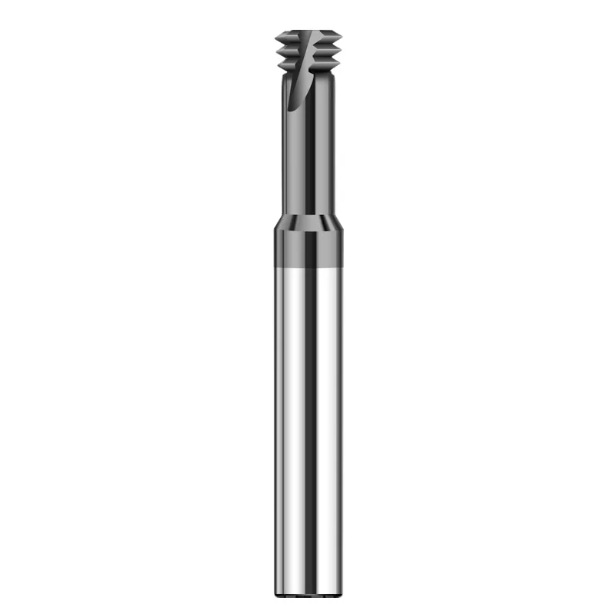
Feature 3: Optimized Ultrafine-Grain Substrate and Core Thickness Ratio for HRC55 Thread Milling Cutters
Hardened workpieces exceeding 50 HRC will destroy standard carbide tools during the initial entry pass. Relying solely on hard coatings is a mistake because weak substrates yield under heavy loads, causing surface layers to flake off. Hrc55 carbide thread milling cutters require sintered ultrafine-grain tungsten carbide rod stock combined with an increased core thickness.
Increasing core thickness demands a careful compromise regarding available chip evacuation space. Wider cores leave shallower flutes, which can trap chips in ductile materials. Fortunately, hardened mold steels produce brittle, granular chips that require minimal flute volume, allowing us to maximize rigidity and eliminate tool deflection entirely.
Impact-Resistant Rigidity for Pre-Hardened Mold Steels and Quenched Parts
Tangential cutting resistance skyrockets when milling pre-hardened mold steels like NAK80 or H13. When core thickness drops below 50% of the tool diameter, long overhangs cause microscopic body bending. We increase the core thickness ratio of our solid carbide thread milling cutters to 60% or 65% on five-axis machines to double static rigidity.
However, high-core designs leave very little clearance for pre-drilled hole inaccuracies. If a pilot drill drifts or leaves a hard entry crust, rigid tools risk severe mechanical interference and breakage. Strict control over pre-drilled hole coaxiality is mandatory when utilizing high-rigidity tooling configurations.
Thermal Fatigue Resistance of Sub-Micron Grain Structures During Interrupted Cutting
Helical thread milling subjects cutting edges to continuous thermal expansion and rapid cooling cycles. Coarse-grained tools accumulate tensile stress at grain boundaries, which quickly forms destructive micro-cracks. For our thread milling cutters for steels, we refine hard-phase grains to a sub-micron range of 0.4–0.6 μm to block crack propagation paths.
This grain refinement enhances thermal fatigue resistance without sacrificing impact toughness or cobalt binder integrity. Sub-micron rod stock withstands localized 900°C temperature spikes during hardened steel machining. This ensures every tooth maintains a consistent geometric profile throughout extended multi-hour production cycles.
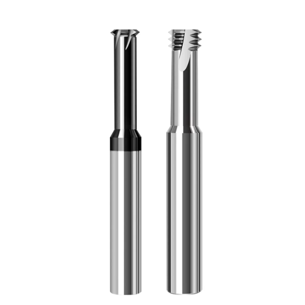
Feature 4: AlCrN and AlTiSiN Coatings Withstanding Extreme Temperatures of 1100°C
Milling high-strength alloy steels exposes tool tips to extreme temperatures, high pressures, and heavy friction. Standard TiN or basic TiAlN coatings degrade rapidly above 800°C, leading to catastrophic coating spalling and substrate ablation. Our thread milling cutters for steels utilize AlCrN and silicon-doped AlTiSiN nanocomposite coatings capable of handling thresholds exceeding 1100°C.
High aluminum content forms a dense, protective aluminum oxide layer that shields the tungsten carbide substrate. However, PVD coatings require exceptional surface smoothness to prevent chip cold-welding. We perform mirror-finish abrasive blasting on tool flanks and apply secondary micro-droplet removal to lower friction and optimize chip flow.
Preventing Adhesion and Flank/Crater Wear in Dry and MQL Machining
Dry machining and Minimum Quantity Lubrication prevent thermal shock cracking during interrupted cutting in structural steels. Without flood coolant, severe flank friction can trigger rapid crater wear and tool breakdown. Solid carbide thread milling cutters featuring multi-layer AlCrN coatings utilize natural self-lubricating properties to block iron diffusion.
Refining surface roughness to a mirror finish prevents plastically deformed steel chips from mechanically interlocking with tool flanks. This physical barrier maintains a stable thermal curve even without liquid coolant. This technology guarantees tight surface roughness tolerances across entire production batches of challenging metal components.
Solving Coating Buildup at the Thread Root for 0.5mm Fine Pitches
Fine threads with a 0.5mm pitch or smaller present unique dimensional challenges due to PVD plasma behavior. Tip discharge effects cause 60-degree thread crests and tiny roots to accumulate excessive coating thickness. Consequently, many standard thread milling cutters suffer from buildup that interferes with Go/No-Go gauge inspections.
To solve this, we employ a low-stress, ultra-thin gradient nano-deposition process that restricts total thickness to 2.5 μm. During five-axis grinding, our programming applies a micron-level geometric compensation specifically tailored for root accumulation. This closed-loop control guarantees that thread crests and roots match precise industry profile tolerances.
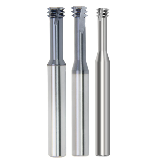
Feature 5: Axial and Radial Internal Coolant Holes with Directed Jets
When machining alloy steel in narrow blind holes, external coolant struggles to penetrate the rotating air curtain. Operators often bend external lines, but the fluid merely swirls outside the cutting zone. Our thread milling cutters for steels solve this with dedicated internal coolant channels. High-pressure fluid is delivered straight to the active cutting zone.
Carbide blanks with internal coolant holes require higher sintering costs and rigorous verification. Oversized holes compromise tool body rigidity during aggressive high-speed steel side milling. Conversely, undersized holes fail to generate adequate fluid pressure and flow rates. Through fluid simulation, we balanced dual-helical channels to maintain impact resistance.
The Challenge of Chip Evacuation in Deep Blind-Hole Threading: Preventing Secondary Chip Damage to Formed Threads
In deep blind-hole threading, trapped metal chips cause severe secondary crushing and tool damage. Steel chips often become wedged between the cutting flutes and hole walls. When using solid carbide thread milling cutters, inadequate evacuation forces cause chips to score precision threads. This generates annoying burrs and degrades the flank surface finish.
Increasing spindle speeds only intensifies friction and thermal accumulation at the hole bottom. Cutting data reveals that secondary shearing triggers violent, irregular spikes in spindle motor torque. Directed cooling channels use dynamic fluid thrust to evacuate chips immediately. This completely eliminates secondary contact between chips and formed thread profiles.
How High-Pressure Emulsion Precisely Flushes the Tooth Root and Forces Chips Out of the Hole
Standard through-spindle coolant delivery often creates counter-rotating eddies in deep blind holes. To optimize cnc thread milling operations, we integrate micro-lateral radial outlets. These outlets align directly with the rake face shear zone and tooth gullets. When high-pressure emulsion fires, dynamic fluid dislodges fine chips from the roots.
This precise jet angle lowers temperatures while establishing a continuous outward flow field. Rebounding fluid creates a high-speed return force along the variable-helix chip channels. This effectively pumps fragmented steel chips out past the workpiece face. Although this requires high-pressure filtration systems, it delivers an interference-free environment.
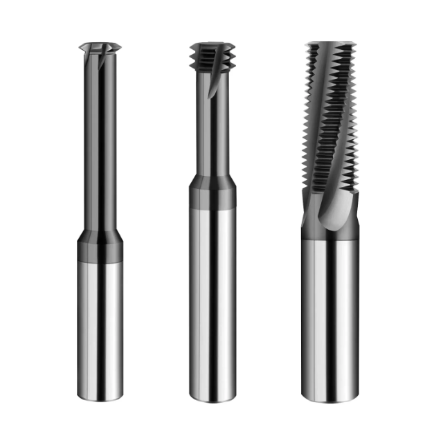
Feature 6: Short Flute Length & Reinforced Neck
Machinists often prefer maximizing flute length to cut full thread depths in one pass. However, full-flute engagement in strong alloy steels creates massive lateral cutting forces. In developing thread milling cutters for steel, we combine short edges with reinforced necks. The active cutting edge is strictly limited to three or five pitches.
This multi-pass strategy delivers vastly superior machining stability across demanding industrial setups. Short flutes restrict cutting resistance to a narrow axial window for smooth motor loads. In shops with average rigidity, this approach yields better tool life than single-pass cuts. It subjects the tool body to pure bending forces rather than twisting.
Dispelling the “Longer Flute is Better” Myth: The Key Formula for Minimizing Deflection
Tool tip deflection is proportional to the cube of the overhang length. When inverted tapers appear, operators often blame speed instead of checking structural rigidity. Standard thread milling cutters featuring full-body flutes have slender core thicknesses. In deep holes, this slender core leads to hidden tool deflection and thread distortion.
By switching to short cutting edges, we preserve a robust shank body along the extension. The unmachined neck area provides a cross-sectional area several times larger than the core. This minimizes deflection down to the micron level based on mechanical beam physics. Consequently, the tool tip maintains a firm grip on the programmed helical path.
Rigidity Optimization for 2.5D–3D Deep-Hole Structural Components (Aerospace & Energy Sectors)
Machining 2.5D to 3D deep holes in aerospace alloys historically caused severe tool chatter. Traditional long-edge cutters generated poor thread flank roughness in chromium-molybdenum steels. Our field optimization strategy pairs short-edge tools with tapered reinforced necks. We also deploy custom CNC macro programs for helical multi-step entry.
This segmented approach eliminates wasted time spent on repeated spring passes. Large reinforced necks absorb bending moments, keeping pitch diameters within tight tolerances. For expensive structural components, this dimensional reliability prevents costly workpiece scrapping. It delivers the structural integrity that demanding aerospace workshops require.
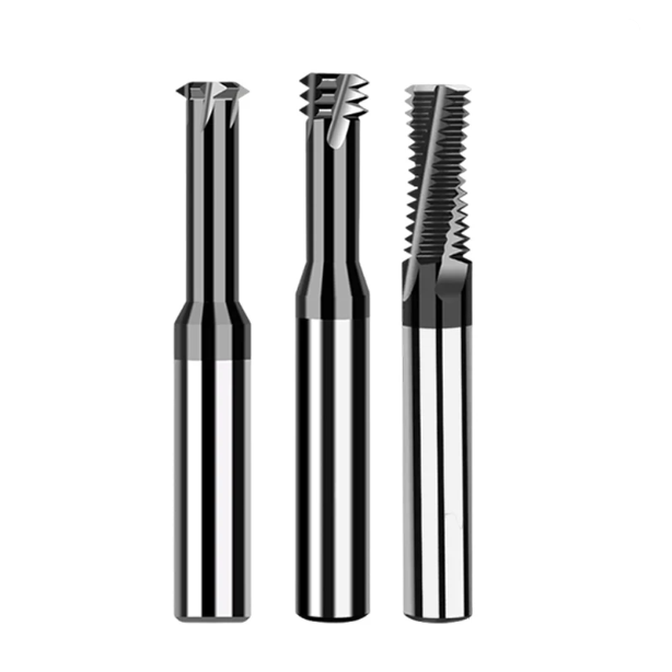
Feature 7: Corrective Crest Grinding Ensuring 100% Compatibility with Go/No-Go Gauges
Quality inspectors often struggle when Go/No-Go gauges jam on newly threaded deep holes. Even with flawless CNC compensation, gauges fail if crest interference occurs. Steel workpieces undergo micro-deformation under cutting forces during machining cycles. Grinding sharp 60-degree crests creates tiny protrusions that collide with standard gauges.
We solved this discrepancy by implementing corrective crest-compensation grinding mechanisms on our lines. Our profile designs apply micron-level corrections to crest flats and root radii. This intentional clearance accommodates chip deformation and elastic spring-back during cutting. While dressing complexity increases, it guarantees 100% compatibility with standard gauges.
How Grinding Wheel Dressing Errors in Precision 5-Axis Tool Grinders Affect Crest Truncation and Root Radius
Grinding wheel dressing precision dictates successful tooth profiles on carbide thread tools. Diamond dressing rolls must maintain extreme accuracy without thermal runout or vibration. Even a 0.001 mm runout transfers directly onto the tiny tool crests. A dull dressed wheel leaves an improper root radius that invites stress cracks.
Balancing wheel wear against dressing frequency requires years of machine commissioning expertise. We embed automated compensation algorithms into our grinding programs to ensure consistency. This strict control over micron-level paths separates industrial tools from ordinary alternatives. It guarantees reliable performance across large production batches.
Solving the Common Quality Control Issue: “Correct Pitch but Fails the Go-Gauge”
When a correct pitch fails gauge tests, operators often alter programs or replace spindles unnecessarily. The real culprit usually lies in faulty tool profile envelope design. Steel shear resistance forces tool tips to undergo minor elastic deflections. Standard straight profiles yield thread pitch diameters that are much too tight.
Buyers should evaluate actual sample verification rather than relying solely on initial edge sharpness. A superior thread milling cutter must pass rigorous gauge inspections on the first trial cut. This eliminates tedious test adjustments and saves valuable machine uptime. In mass production, this ensures your facility meets tight delivery deadlines.
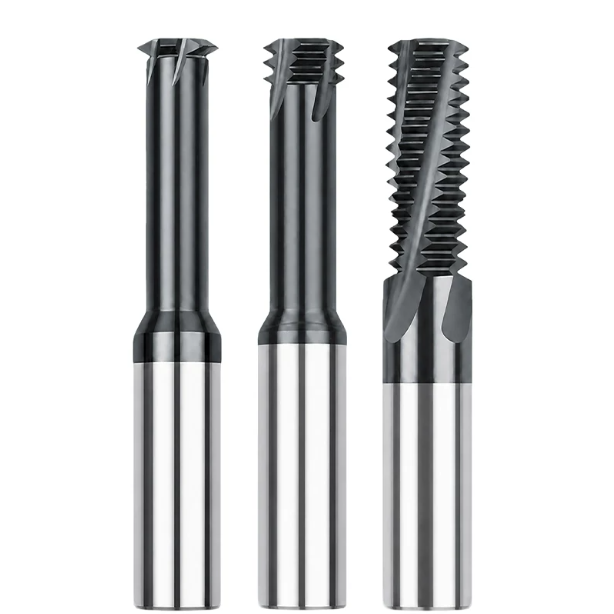
Identifying Genuine Original Manufacturers: How Workshop Engineers Evaluate Thread Milling Cutter Manufacturers
Selecting tools can feel overwhelming in a market flooded by traders and private-label marketers. Workshop supervisors struggle to distinguish genuine thread milling cutter manufacturers from resellers. Over sixteen years hosting industry peers for factory audits, we learned reliable suppliers avoid glossy brochures. They prove capabilities through self-controlled processes from bar peeling to 5-axis grinding.
Assessing tool makers requires looking beyond unit pricing to evaluate engineering responsiveness for specialized parts. True original manufacturers offer comprehensive process solutions for difficult aerospace alloys or mold steels. They optimize everything from flute geometry to micro-scale edge strengthening. This technical depth separates ordinary contract producers from true custom innovators.
Scrutinizing Grinding Equipment and In-Line Full Inspection: Walter/Rollomatic Machines and Profilometers
Qualified carbide workshops feature rows of high-precision 5-axis CNC grinding machines in temperature-controlled rooms. Producing precise thread pitches without equipment from Walter or Rollomatic is virtually impossible. High-rigidity spindles and linear motors provide the physical foundation ensuring accurate tool geometry. High-end machinery guarantees every manufactured tool matches exact technical specifications.
Advanced equipment alone does not guarantee inspection-free parts without rigorous quality control checkpoints. Reputable thread milling cutter manufacturers subject every batch to 100% optical profiling before shipping. This zero-tolerance approach scans tooth profiles with laser instruments to prevent tip runout. Rigorous in-line inspections ensure entire workpieces are never scrapped on the shop floor.
Technical Support Standards from Premium Thread Tool Manufacturers for Special Alloy Steels
Standard 60-degree profiles fail to meet sealing requirements in heavy equipment and aerospace sectors. Workshops constantly seek partners capable of developing non-standard thread tools for exotic materials. When machining titanium alloys or stainless steel, top-tier suppliers request detailed drawings. They analyze pilot hole tolerances and machine spindle rigidity before recommending parameters.
In-depth technical support includes customized macro programming and multi-pass cutting path optimization. When unexpected chatter or chip evacuation issues occur, experts must reverse-calculate forces quickly. Modifying tool rake angles and edge honing specifications within hours solves complex challenges. This integration of tool manufacturing with machining processes guarantees reliable shop-floor productivity.
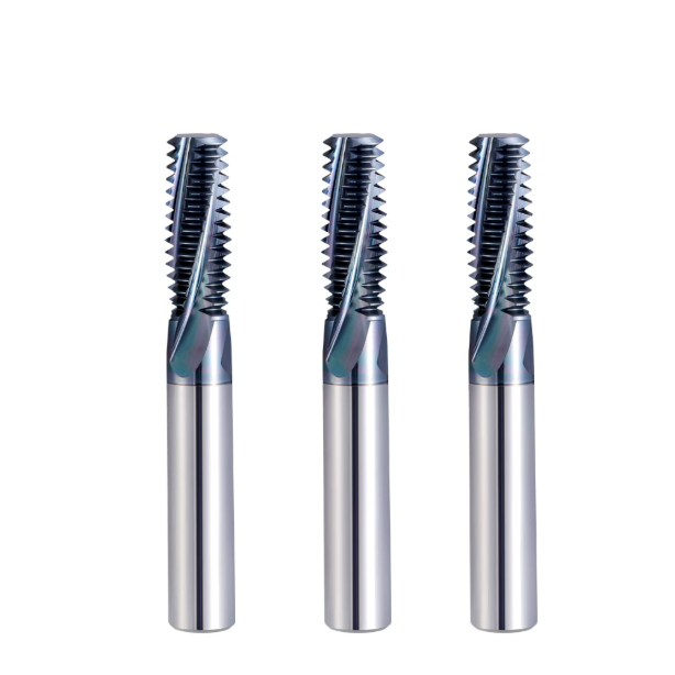
Fine-Tuning Guidelines for CNC Thread Milling Parameters from Our Field Engineers
Effective thread milling relies on a systems-engineering approach rather than isolated parameters. Ground principles like vibration-dampening pitches, micro-edge honing, and coatings form a cohesive design. However, even premium tooling fails if CNC programming paths and cutting parameters remain unoptimized. Proper execution prevents edge chipping and profile deviations during critical machining operations.
Mandatory 180° Arc-in/Arc-out Logic for Helical Interpolation
Programming CNC thread milling operations requires avoiding direct linear tangential entry paths. Abrupt linear engagement imposes massive peak impact forces that cause instant edge chipping. Our verified solution mandates 180° arc-in and arc-out toolpaths for smooth transitions. Transitioning with increasing radius ensures each tooth enters the cutting zone evenly.
This balanced engagement completely eliminates microscopic chatter marks at the point of entry. Cutting forces rise smoothly along a controlled curve rather than spiking abruptly. Protecting the cutting edge during initial contact maximizes overall tool longevity. Programmers should always verify these smooth transition arcs before running cycles.
Layered Entry Strategy for Hardened Steel: Why 2–3 Pass Depth Allocation Matters
Machining HRC55 hardened mold steel requires distributing total cutting depth across passes. Attempting full-depth removal in one pass triggers tool deflection and thermal fatigue. Our field optimization strategy recommends a multi-pass depth allocation approach. The first pass clears roughing allowances while subsequent passes handle finishing stock.
This layered depth strategy effectively dissipates heat and controls flank wear rates. Utilizing hrc55 carbide thread milling cutters with multiple passes ensures precision fits. If your shop experiences frequent tool breakage or taper issues, pause to evaluate parameters. Sharing your specific application challenges allows us to recommend tailored cutting strategies.






