
Last month, an aerospace supplier in Ohio snapped three taps in a row while machining M16×1.5 deep-hole threads on a batch of 4340 landing gear sleeves (quenched and tempered to 36 HRC). The final component was scrapped, the machining center went down for half a shift, and direct part losses topped $3,000.
The shop’s tooling supervisor dialed our support line that evening. His frustration was obvious: “Why do taps run smoothly on 1018 cold-rolled steel, but the moment we load 4140, 4340, or pre-hardened P20, tools snap or the No-Go gauge fails after two turns?”
Over our 16 years of supporting precision machine shops across the US and Europe, this call is an all-too-familiar scenario. Chrome-moly alloy steels and pre-hardened tool steels possess elevated tensile strength, pronounced strain-hardening, and spring-back tendencies that routinely exceed the torsional yield limits of cut or form taps.
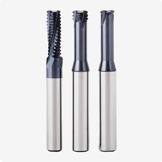
To safeguard high-dollar components from scrap, we no longer advise using taps for these applications. Machine shops gain far greater process reliability by adopting an engineered thread mill for steel solution.
However, loading a thread milling cutter into the tool holder does not solve everything on its own. In our field audits, we consistently see programmers repeating three critical errors:
- Omitting tool center-line feed compensation, which spikes the effective outer-diameter chip load and chips cutting edges.
- Running full-profile multi-tooth cutters in deep holes, creating severe pitch taper near the hole bottom due to tool deflection.
- Flooding high-hardness alloys with standard water-soluble coolant, causing thermal fatigue cracks along the carbide cutting flutes.
Eliminating these failures requires solid carbide cutters matched to the material’s metallurgy, radial multi-pass toolpaths, and verified surface footage and feed calculations. If your machinists are hovering over the feed-hold button on a run of 4140 or P20 parts, are you completely sure your current tooling and interpolation program are truly optimized for alloy steels?
Why We Recommend Overseas Workshops Replace Taps with Carbide Thread Mills for Machining 4140 and 4340 Steels
When supporting heavy-equipment job shops in the US, we regularly see operators dreading tap cycles on 4140 and 4340. Once quenched and tempered, these medium-carbon chrome-moly steels exert extreme radial springback against the tool body during thread cutting. This elastic recovery spikes frictional torque right at the tap shank. If chips pack even slightly in the flutes, the tool shears off instantly, forcing costly EDM burnouts that risk structural part damage.
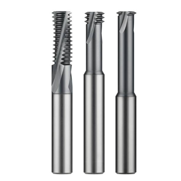
That is why we consistently steer machining facilities toward premium carbide thread mills for these challenging alloys. Thread milling uses intermittent point-contact cutting, which generates predictable, stable spindle loads instead of escalating continuous friction. Even if a cutter chips or reaches end-of-life, the tool never seizes inside the bore; small fragments blow out freely with air. You eliminate catastrophic part scrappage and gain a stable, highly repeatable threading cycle.
Blind Holes in 28–36 HRC Pre-Hardened Steel: Shop-Floor Data on Eliminating Scrap Caused by Broken Taps
Last year, we assisted a Wisconsin hydraulics manufacturer running 32 HRC 4140 manifold blocks with over a dozen deep M14×1.5 blind holes per piece. They were running cobalt taps, suffering micro-chipping and catastrophic tool breakage every 120 holes on average. This left them with an unacceptable 3% to 5% scrap rate. Without altering their pilot drill diameter, we transitioned their setup to an application-specific thread mill for steel using a stepped multi-pass routine.
The production run of 500 blocks finished with zero broken tools and zero scrapped parts. Cycle time per hole increased by roughly 8 seconds, but total cost per finished hole dropped nearly 40% once EDM rework and scrap write-offs vanished. Chasing a few seconds of cycle time is pointless if a broken tool scraps a finished component; predictable process reliability always delivers higher net profit.
Why 4340’s High Tensile Strength Favors High-Rigidity Solid Carbide Thread Mills over Indexable Insert Tools
When machining 4340 steel with tensile strength exceeding 1,000 MPa, cutting resistance climbs steeply. Many shops cutting M20 or larger threads immediately reach for indexable insert tools to reduce consumable insert costs. However, production tests across aerospace plants consistently reveal the mechanical limits of indexable bodies. Pocket screws, shims, and thin cutter pocket walls struggle to resist high radial pushback, triggering micro-chatter upon initial tooth entry.
This deflection leads to surface chatter and creates an inverted taper where the Go plug gage sticks halfway down the hole. For structural 4340 parts, we consistently advocate for solid carbide thread mills engineered with heavy core webs and helical flutes. The solid, sub-micron tungsten substrate provides the bending stiffness needed to stop deflection in deep holes, holding accurate pitch diameter without endless cutter comp adjustments.
Selection Guidelines for Thread Mill Types for P20 and Medium-Carbon Low-Alloy Steels
When machining large P20 mold bases or slides, engineers frequently ask why tooling that runs 4140 cleanly leaves torn, fuzzy threads on P20. While P20 is supplied pre-hardened (28–32 HRC), it is noticeably more ductile and gummy than standard 4140. Grabbing generic cutters off the shelf causes material smear along the flank, creating microscopic tears that lead to bolt galling during final mold assembly.
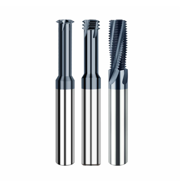
Balancing surface finish and tool life requires matching cutter geometry to hole depth, pitch, and machine rigidity. Understanding the physical boundaries of various thread mill types allows you to prevent tool deflection while staying within spindle torque limits. There is no single universal cutter; knowing when to swap geometries is what separates repeatable production from constant thread rework.
Comparison of Straight-Flute vs. Helical-Flute Thread Mills: Performance in Deep-Hole Chip Evacuation and Cutting Resistance
Straight-flute designs provide solid core stiffness and symmetrical grinding geometries. In shallow holes under 1.5×D or thin-walled setups, they offer rigid support and are simple to regrind accurately. However, in deep low-alloy steel bores, straight flutes fail to lift chips axially. Fine steel chips pack in the flutes, recut against the crests, and cause premature tooth chipping.
For thread depths exceeding 2×D, we consistently specify helical flutes with a 15° to 30° helix angle. Among standard thread mill types, helical flutes ensure progressive shear engagement rather than a sudden full-face impact. This dynamic lowers peak spindle load and evacuates chips cleanly out of the bore, keeping cutting edges intact.
Single-Form vs. Multi-Form Thread Mills: Eliminating Taper Deflection Based on the Length-to-Diameter Ratio
A recurring defect in deep P20 holes is thread taper, where the Go plug gage enters the hole mouth but jams halfway down. Programmers often favor multi-form cutters to complete threads in a single 360-degree helical pass. However, full-profile engagement spikes radial tool pressure. When overhang exceeds 2.5×D, cutter deflection causes an undersized pitch diameter near the hole bottom.
When facing deep blind holes, switching to single-form or short three-tooth cutters solves this bottleneck. These versatile thread mill types reduce cutting pressure to a fraction of full-profile engagement, virtually eliminating radial push-off. While multi-pass cycles take a few extra seconds, they guarantee true pitch diameter cylindricity and eliminate time-consuming tool-comp adjustments.
Flat-Bottom Thread Milling for Blind Holes with Coolant-Through Capability: Shop-Floor Chip Evacuation and Anti-Tangle Settings
In hydraulic manifold blocks and mold inserts, fluid channels demand full thread depth right down to the bottom face. Standard external flood coolant bounces off the hole opening and cannot penetrate this tight dead zone. Swarf nests at the bottom, creating a chip slurry that grinds against the cutter tip, rapidly destroying end teeth after only two or three parts.
Using dedicated internal through-spindle coolant tools completely turns the tables. We advise keeping coolant pressure above 200 PSI (15 bar), paired with cutters featuring end-clearing relief. The pressurized jet flushes broken chips straight up the flutes, keeping the pocket clean while delivering full, sharp threads directly to the bottom.
Machining Heat-Treated Alloy Steel (48–55 HRC): Practical Solutions Using HRC55 Carbide Thread Mills
When hardened 4140 or 4340 components hit 48–55 HRC, the material shifts into a dense tempered martensite structure. Shops typically rely on slow EDM burning to avoid snapping taps in this zone. However, EDM leaves a brittle, recast “white layer” that easily initiates stress fractures under fatigue.
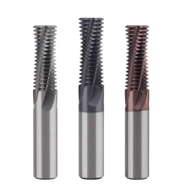
Direct milling on hardened substrates requires matched toolholder grip, true-running spindles, and tuned micro-geometries. Deploying specialized HRC55 carbide thread mills allows shops to cut full threads directly after heat treatment. This eliminates tap breakage and secondary part distortion, holding critical blueprint tolerances reliably.
Substrate Selection for HRC55 Carbide Thread Mills: Sub-Micron Grades for Suppressing Micro-Chipping
Machinists often assume that cutting harder steel demands the hardest, most brittle carbide grade available. On the contrary, cutting data shows that beyond 50 HRC, tools fail from edge chipping under cyclical shock rather than gradual flank wear. Micro-chipping on the cutting edge quickly accelerates into total tooth failure.
To counter this, our HRC55 carbide thread mills utilize sub-micron tungsten substrates with grain sizes of 0.4 to 0.6 microns. This dense grain matrix halts micro-crack propagation while maintaining balanced cobalt distribution. The result is superior fracture toughness that absorbs interrupted cutting shock against hard inclusions without sacrificing wear resistance.
Coating Selection for Hardened 4140/4340: Service Life Comparison of High-Temperature Coatings on HRC55 Carbide Thread Mills
Point contact temperatures easily pass 1,470°F (800°C) when cutting hardened 4340. Standard TiAlN coatings oxidize rapidly under these conditions, flaking off after roughly 15 holes and leaving bare carbide to fail from friction. Heat dissipation is the primary challenge in this hardness window.
In contrast, advanced nanocomposite AlCrN coatings applied to our HRC55 carbide thread mills consistently yield over 45 holes per tool. High aluminum content forms a dense protective oxide barrier at high temperatures, withstanding heat up to 1,830°F (1,000°C). This thermal barrier shields the substrate and reduces rake face friction during chip formation.
Air Blast or Wet Machining? Validating Cooling and Thermal Shock Control for HRC55 Carbide Thread Mills in Customer Workshops
Coolant strategy in hardened steel sparks heated debate on shop floors. Many operators blast water-soluble flood coolant directly at the tool, thinking it extends life. In reality, cycling between intense cut heat and sudden liquid quench triggers severe thermal shock, forming comb-like stress cracks that snap cutter teeth.
We advocate running clean, dry compressed air or Minimum Quantity Lubrication (MQL) on our HRC55 carbide thread mills. Dry machining keeps cutting temperatures stable, eliminating micro-fractures from thermal cycling. Meanwhile, high-pressure air clears hot, powdery chips from the hole, stopping swarf recutting from scoring the finished thread flanks.
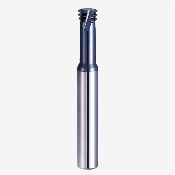
Thread Mill Feed and Speed Strategies for 4140, 4340, and P20 Steels
A frequent issue we troubleshoot on the shop floor is spindle groaning or immediate tooth chipping during circular entry, even when programmed with catalog numbers. The root problem is rarely machine rigidity or raw tool hardness; it stems from applying linear milling feeds directly to internal helical arcs. Tough alloys like 4140, 4340, and P20 resist plastic deformation aggressively. As the cutter interpolates along an internal arc, tool engagement wrap spikes drastically, creating severe cutting resistance.
Dialing in a safe thread mill feed and speed setup requires programming for dynamic circular contact rather than linear passes. Balancing actual chip load at the tool’s outer cutting edge against CNC axis movement is essential to prevent chatter. When you synchronize programmed axis motion with actual tooth-engagement physics, you protect the cutting edges, eliminate taper, and maintain tight thread tolerances.
The Key to Preventing Tool Deflection: Correction Formulas for Tool Center vs. Outer Edge Feed Rates
If you input the peripheral feed rate directly as the G-code F-value during internal threading, actual tooth load increases two to threefold. CNC controls track the center axis of the tool, not the outer cutting diameter. Because the tool center travels along a much smaller radius than the cutting teeth, uncorrected center feeds overload the flutes instantly, triggering tool deflection and tapered threads in deep bores.
To correct this, calculate the center feed by multiplying the outer feed by the ratio of hole major diameter minus cutter diameter over hole major diameter. Applying this formula ensures your programmed thread mill feed and speed values maintain an accurate chip thickness per tooth. This eliminates excessive radial push-off and prevents pitch diameter collapse at the bottom of the bore.
Recommended Thread Mill Feed and Speed Ranges for 4140 and P20 Steels (Cutting Speed and Feed per Tooth)
For pre-hardened 4140 and P20 mold steels (28–32 HRC), assuming spindle runout is kept under 3 microns, we suggest starting at 70 to 95 m/min surface speed. This velocity activates wear-resistant coatings without accelerating crater wear from hard alloy inclusions. For higher-tensile 4340, we advise dialing back cutting speed to 60–80 m/min to maintain edge integrity.
Feed per tooth requires equal care: setting feed rates too low causes teeth to burnish rather than cut, inducing rapid work hardening. For reliable thread mill feed and speed performance, maintain an outer feed per tooth between 0.03 and 0.06 mm. Moderating surface speed while keeping positive chip engagement ensures teeth slice cleanly through the steel, significantly extending tool life.
Radial Multi-Pass and Arc Entry Strategies: Solving Shop-Floor Issues Where the No-Go Gage Enters but the Go Gage Binds
Shop-floor rework spikes when thread gage inspection fails: the Go gage binds while the No-Go gage wobbles loosely. In high-tensile 4140 or 4340, taking full thread depth in a single radial pass creates massive lateral pressure that flexes the cutter, distorting flank angles. Dividing the radial cut into stepped passes balances cutting force and preserves true thread geometry.
We recommend roughing at 65% radial depth, semi-finishing at 30%, and finishing at 5%, followed by a spring pass for deep holes over 2.5×D. Never plunge straight into the bore wall; always use a smooth 90° or 180° tangential arc entry. Combining proper tool entry with dialed-in thread mill feed and speed parameters ensures threads pass Go/No-Go plug inspection on the first run.
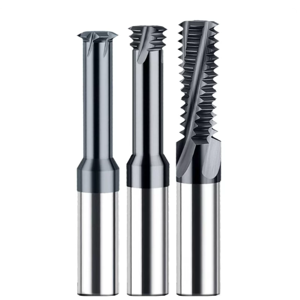
How We Control Milling Quality for Steel Parts as a Professional Carbide Thread Mill Manufacturer
Addressing alloy steel springback, chip evacuation in mold cavities, and thermal stress in hardened steels always leads back to cutter manufacturing quality. Even with verified feeds, speeds, and toolpaths, an out-of-spec tool cannot cut accurate threads. Sub-micron errors in pitch spacing, flank symmetry, or edge prep inevitably lead to failed Go/No-Go gage inspections.
As an experienced carbide thread mill manufacturer, we know nominal catalog specs mean nothing without predictable cutting performance under dynamic load. Building cutters for pre-hardened and structural steels requires tight grain structure control, rigid multi-axis grinding, and micro-engineered edge prep. If your current tooling underperforms, examine whether tool manufacturing tolerances are multiplying your machining errors.
From Raw Rod to Finished Grind: How a Carbide Thread Mill Manufacturer Limits Radial Runout (TIR) to Under 3 Microns
During high-speed helical interpolation in alloy steels, just 5 microns of radial runout creates severe load imbalances that chip individual teeth prematurely. When machining tough chrome-moly alloys, even tooth load distribution is essential for consistent wear. Keeping Total Indicated Runout (TIR) within an ultra-tight band during manufacture prevents early edge failure.
As a dedicated carbide thread mill manufacturer, we grind helical profiles on precision 5-axis tool grinders while holding coolant temperatures within ±0.5°C. This temperature control eliminates thermal wheel drift and prevents cumulative pitch pitch errors across multi-tooth forms. If your premium toolholders still produce chatter in 4140, check your cutter’s static TIR to confirm it meets the 3-micron benchmark.
Top Three Threading Defects Reported by Western Machine Shops and Our Edge-Honing Countermeasures
Quality records from North American and European shops show three persistent threading defects in pre-hardened steels: torn crest burrs, wall deformation on thin sleeves, and rapid pitch drift. Machinists often assume dull tooling causes these tears. In truth, an overly razor-sharp edge micro-chips instantly when striking 4340 or P20, quickly converting cutting into heavy burnishing.
We eliminate this failure mode by applying controlled edge honing with balanced K-factor geometries tailored for structural steels. We hone cutting edges to an 8–15 micron radius and follow with fluid micro-polishing to clear micro-droplets from the rake face. If you fight thread tearing in steel over 30 HRC, inspecting your cutter’s edge hone will likely reveal the root cause of the burring.
Addressing Special Pitches and Deep-Hole Applications: Key Points for Custom Tool Development
In specialized production—such as oilfield valves, aerospace hydraulics, or complex mold slides—standard catalog cutters cannot cover every application. When running blind holes deeper than 3×D, specialized UNJ profiles, or low through-spindle coolant pressures, standard tools slow production and increase scrap risks on expensive parts.
Developing high-yield setups under tight constraints requires technical collaboration with an experienced carbide thread mill manufacturer. Rather than sending basic thread dimensions, share your complete setup: machine taper, spindle torque curves, overhang ratios, core hardness, and coolant specs. If you are starting a challenging alloy steel job, sharing your part drawings and wear samples allows us to engineer flute geometries that run right on the first setup.






